Due to the number of cable joints in HVDC land cables, which can exceed a thousand in a single system, failure rate of such joints plays a major role in overall system reliability. Routine testing according to IEC 62895, using electric field calculations, is used to assess cable joint reliability.
This edited past contribution to INMR by Hansjörg Gramespacher of ec4ac in Switzerland and Hanyu Ye of WissTec in Germany explained that, since field distribution in an HVDC joint is highly sensitive to temperature, some areas inside a joint can experience much higher electric field during operation than during routine testing according to the standard. As such, DC routine tests according to IEC 62895 may not always be sufficient to guarantee high reliability of joints during operation. Rather, to properly cover electric field distribution in these joints at higher conductor temperatures, an additional test is proposed.
In contrast to AC cable systems, electrical energy can be transmitted great distances using HVDC cables. For example, HVDC cable systems are planned for Germany that will have lengths of about 580 km (the South-East Link) and about 700 km (the South Link) respectively. However, due to transport limits for weight, length of a single cable is limited to a maximum of about one km. That means a joint is needed about every km in the case of land cable systems and about 1000 joints must be installed for long HVDC cable systems. Due to this large number of joints in a single cable, reliability of each joint is critical. Based on experience with HV cable systems for AC, it is known that failures of accessories play the major role in unplanned shutdowns with the main reason being errors during installation. By contrast, failures caused by defects in accessory insulation (e.g. impurities, air bubbles, etc.) or by mistakes during production play a comparatively minor role. The reason is that these kinds of failures can normally be detected during routine testing, as required according to IEC 60840 and 62067 for the main insulation of each joint and termination. The question emerges is whether or not these same kinds of failures would also be detected during routine testing of HVDC joints, according IEC 62895.

Failure Experience in HV AC Cable Joints
According to IEC 60840 and 62067, each cable joint for AC high voltage application has to be tested in a routine test with AC voltage of 2.5 x U0 for 30 minutes and 2.0 x U0 for one hour. In addition, each joint has to pass a partial discharge test at 1.5 x U0. Similar routine tests for AC joints are required as well by IEEE 404. These tests aim to guarantee that failures in the main insulation of joints caused by impurities, air bubbles or errors in manufacturing are already detected in the factory. However, even with these routine tests for cable joints and terminations, failures of these components are still the main reasons for the unplanned shutdowns in AC cable systems. For example, results of a CIGRE investigation into AC cable joints between 220 kV and 500 kV showed an annual failure rate of 0.048 failures per 100 joints, i.e. roughly one of 2000 installed joints failing each year. According to this same investigation, typical time to repair the cable system after such failure is about 25 days for this voltage range.
The question is whether one can similarly estimate expected failure rate of HVDC cable joints. Since most such failures at AC are caused by installation errors, it can be assumed that this kind of failure rate will be similar for DC. However, there are differences in the routine tests required for DC cable joints and these might lead to much higher failure rates than for AC joints.
Electric Field Distribution in HVDC Joints
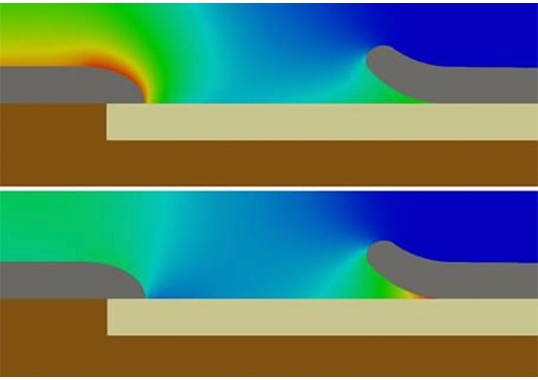
According to IEC 62895, a DC voltage test at ambient temperature with voltage level of 1.85 x U0 for one hour is required for HVDC cable joints. An additional partial discharge test is optional and parameters for this test have to be agreed upon between customer and manufacturer. But in contrast to AC voltages, electric field distribution in HVDC cable joints is highly temperature sensitive and can increase locally by several orders of magnitude if temperature of the cable conductor increases. Fig. 1 provides an example of such change in electric field, showing simulated electric field distributions in joints at different conductor temperatures. The finite element simulations, performed with a finite element tool developed by WissTec, consider change in resistivity with temperature and electric field.
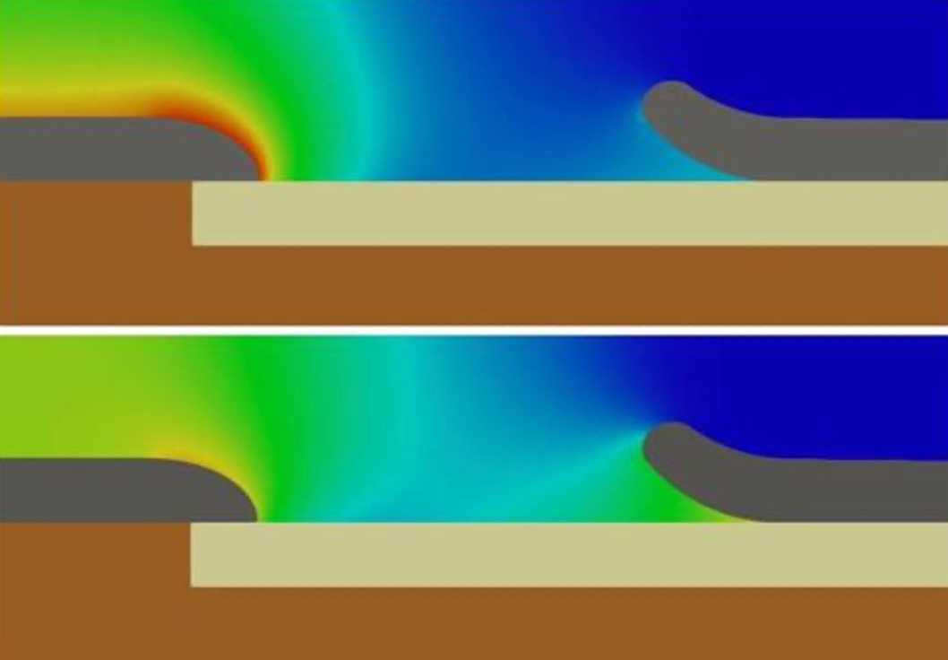
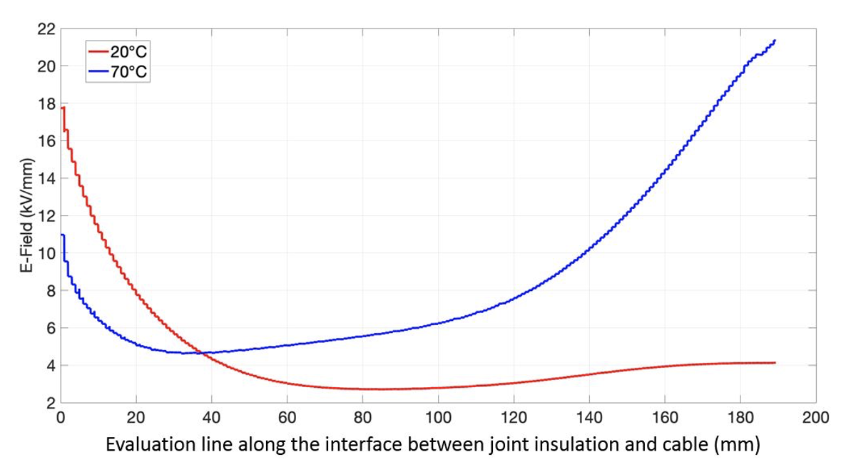
Fig. 1 shows that electric field below the deflector at conductor temperature of 70°C is much higher than at 20°C. This increase in electric field is also shown in Fig. 2, where total electric field is calculated along the interface between joint insulation and cable insulation. Below the deflector, electric field at conductor temperature of 70°C is about five times higher than at a conductor temperature of 20°C. Voltages for this calculation were the same as in Fig. 1 and correspond to test voltages for a 320 kV HVDC joint during routine tests according to IEC 62895.

Comparing Electric Field in Routine Tests & During Operation
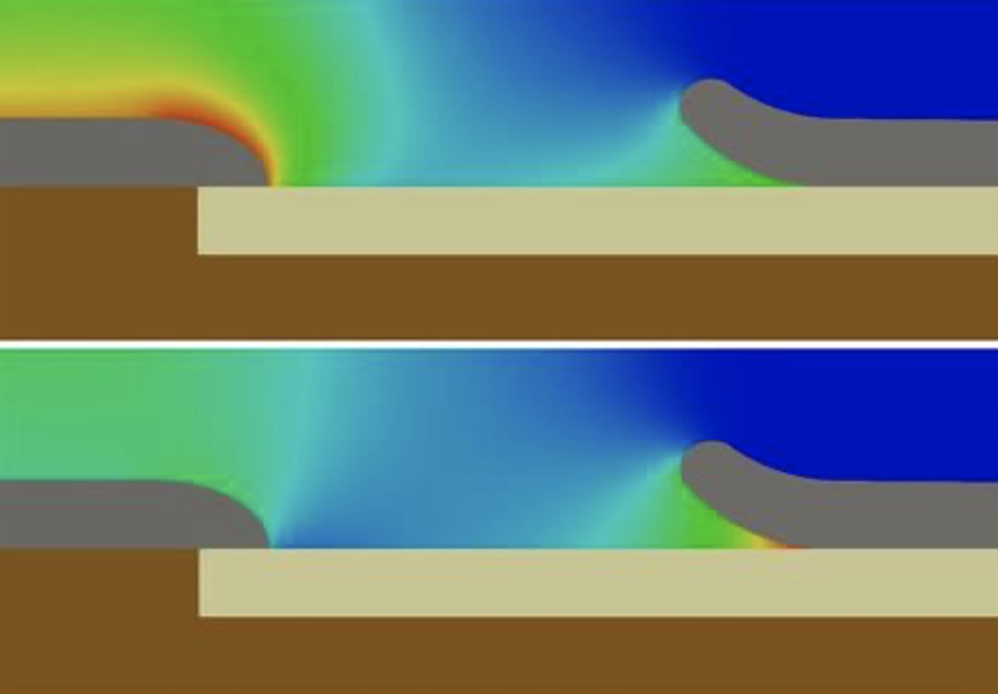
Fig. 3 compares electric field distribution in a 320 kV DC joint during routine testing (592 kV at a conductor temperature of 20°C) and during operation (320 kV at 90°C conductor temperature). The same scale for electric field is used in both images. During operation at high conductor temperature, electric field above the middle electrode of the joint is lower than during the routine test, but electric field below the deflector is much higher. During operation at high conductor temperature, electric field below the deflector is therefore higher than during routine testing. This same behaviour is shown in Fig. 4, where electric field is plotted along the evaluation line between joint body insulation and cable. The diagram compares electric field during operation at three different conductor temperatures versus electric field during a routine test. Electric field close to the deflector during operation is higher than during routine testing at all three conductor temperatures.
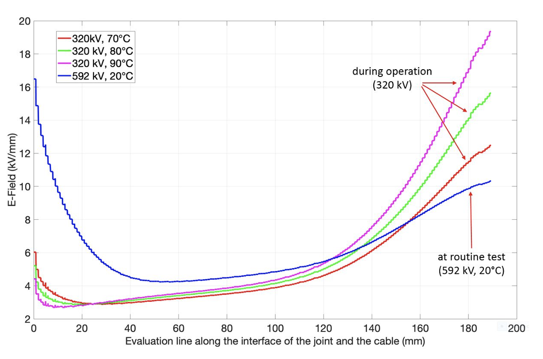
The fact that electric field below the deflector in the joint is higher during operation than during routine tests raises the question whether defects such as protrusions at the deflector or inclusions in the insulation material could be detected during routine testing. Depending on shape and size of such defects, it is possible that they will not lead to puncture during the routine test. However, during operation at higher temperatures and at locally higher electric field, such defects could lead to joint failure. The conclusion is that not all defects that might become critical during operation can be detected during routine tests according to IEC 62895 and this would lead to increased joint failure rate compared to AC joints, where such defects are detected during routine test. To ensure a reliable HVDC cable system containing many joints, routine tests required according to IEC 62895 might not be sufficient.
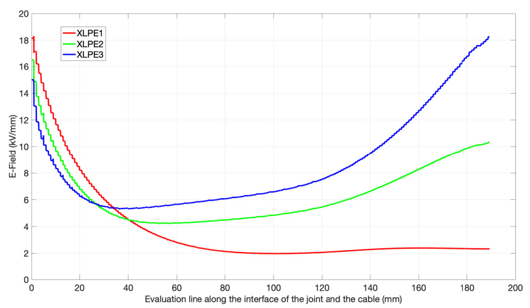
Usually, routine tests are not performed on a cable but rather on adapters that simulate real cable configuration. At DC, electric field distribution in a joint depends on resistivity of the cable insulation and this therefore also has to be considered in design of the insulating material of the adapter during routine tests. Fig. 5 plots calculated electric fields along the interface between joint insulation and cable for three different resistivity values of cable insulation and shows that electric field distribution in the joint changes with different resistivity of cable insulation. In order to ensure the same electric field distribution as during actual service, volume resistivity of the insulation of the adapter used for routine tests must be equal to resistivity of the cable insulation on which the joint will be installed.

Recommendation for Routine Testing of HVDC Cable Joints
Electric field distribution in a HVDC cable joint is highly sensitive to temperature and during operation might be higher in some parts of the joint than during routine tests. As such, it is recommended that the routine test be performed not only at room temperature but also at higher temperatures. This will ensure that electric field in all parts of the joint during the two routine tests is higher than during operation. Even though this test at higher conductor temperatures is not required in IEC 62895, from a reliability point of view it is recommended such additional routine tests be conducted. Moreover, to ensure that electric field distribution in joints during routine tests corresponds to that during operation, it is also recommended using an insulation material in the test adapter that has the same resistivity as the insulation of the cable on which the joint is to be installed.

Conclusions
Simulation has shown that the electric field in some parts of HVDC joints can be higher during operation than during the DC routine test according to IEC 62895. This means that not all critical defects in the joint may be detected, which will increase failure rate in the field. Therefore, it is recommended performing an additional DC routine test with higher temperature. Without such additional testing during routine tests in the factory, there is the risk that failure rate for HVDC joints during operation will be higher than for AC joints. Given the high number of joints in HVDC land cable systems, this could have great economic impact on their operation.
References
[1] IEC 62895: High Voltage direct current (HVDC) power transmission – Cables with extruded insulation and their accessories for rated voltages up to 320 kV for land applications – Test methods and requirements, Edition 1.0, 2017
[2] Internet: www.50hertz.com/en/News/FullarticleNewsof50Hertz/id/5797/direct-current-connections-suedlink-and-suedostlink-grid-operators-start-tenders-for-underground-cables; (Date: 14.03.2019)
[3] CIGRE Working Group B1.10: Update of Service Experience of Underground and Submarine Cable Systems, TB 379, April 2009
[4] Mazzanti G. and Marzinotto M.: Extruded Cables for High-Voltage Direct-Current Transmission: Advances in Research and Development, John Wiley & Sons, Hoboken, New Jersey, (2013)
[5] Gramespacher H. and Ye H.: New Design Concept for Polymeric HVDC Cable Joints, INMR World Congress, Barcelona, 2017