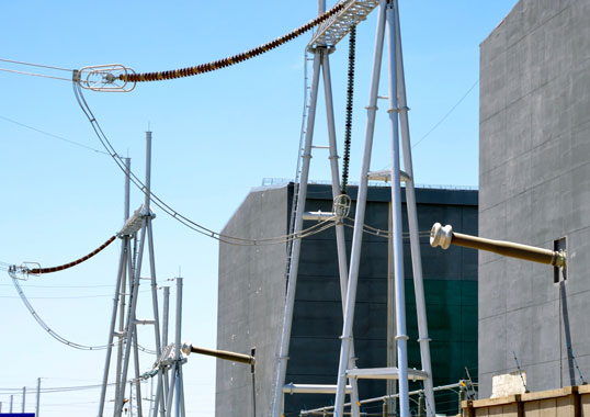
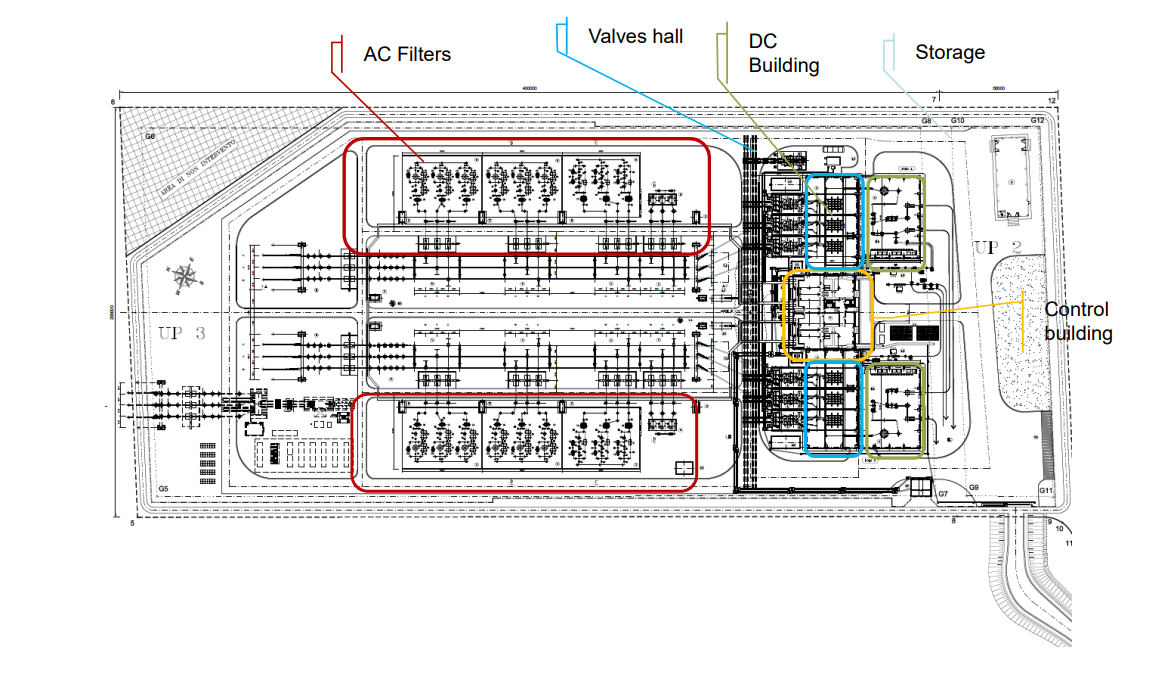
Different bushings are used to connect the AC line to the DC line at HVDC substations, e.g. through the AC yard, within the DC valve hall or inside the DC yard. Depending on converter station design, these bushings can be placed indoors or partially outdoors and therefore exposed to ambient pollution.
This edited contribution to INMR by Laura De Fina, Armando Pastore and other experts at GE Grid Solutions in Italy, in cooperation with Alberto Pigini, discusses pollution design of HVDC-UHVDC bushings for outdoor applications based on IEC/IEEE 65700-19-03, now under revision.

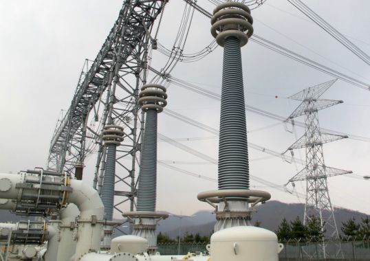
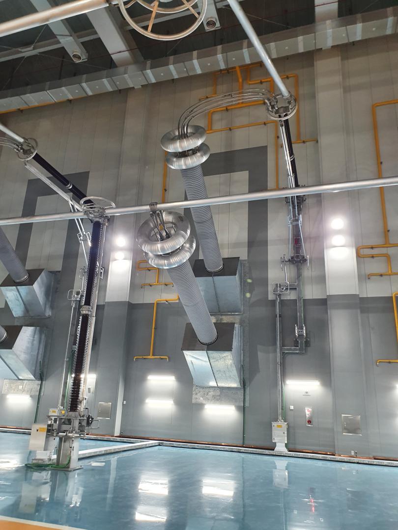
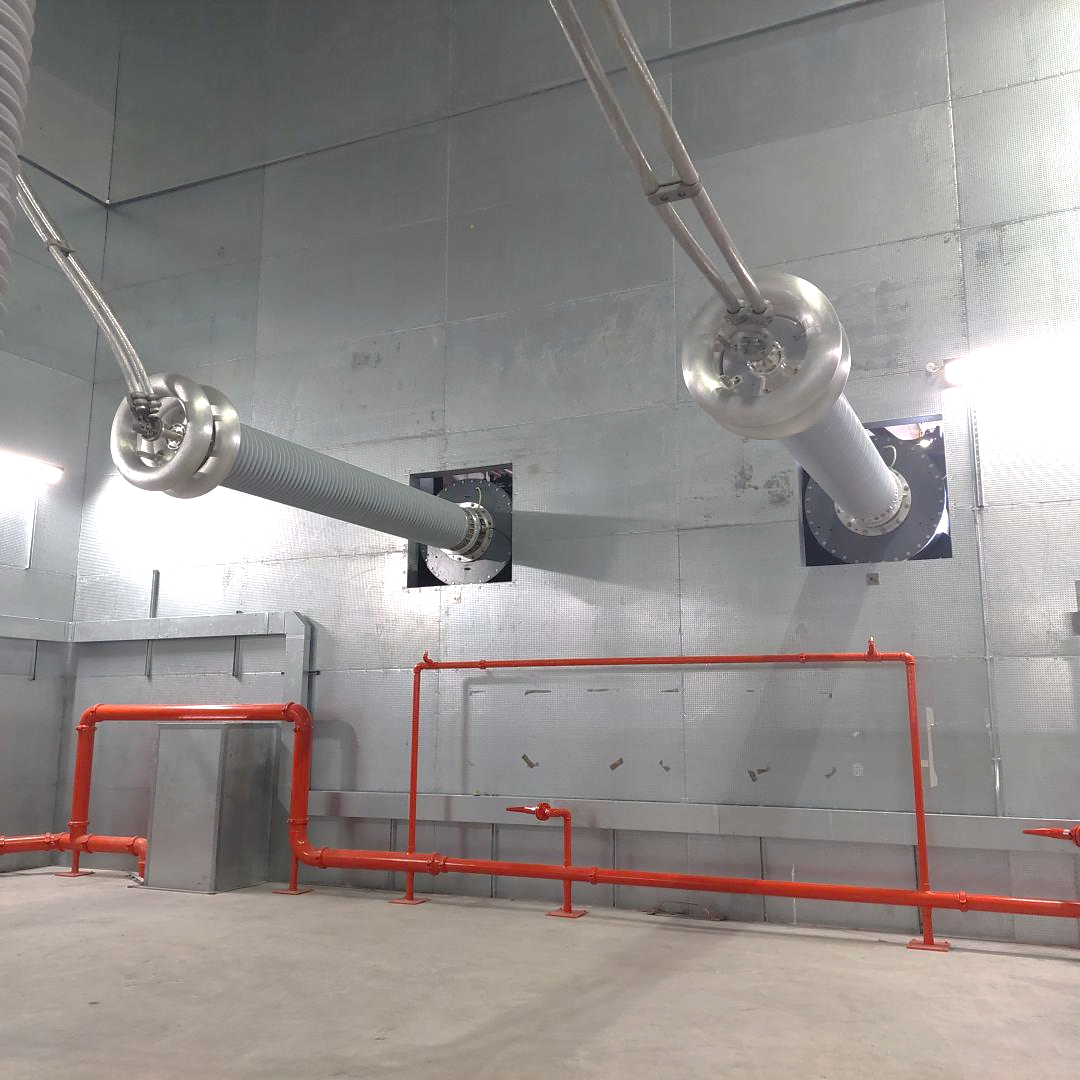
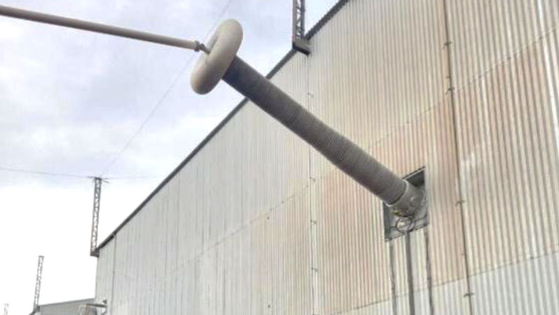
In some HVDC projects, while the transformer is placed externally, the bushings are installed with their airside insulators inside the valve hall. Under these conditions they are protected from external ambient conditions (see Fig. 2). However, at other HVDC substations, even though the transformers are again outdoors in the AC yard, connection to the DC valve hall is achieved by means of wall bushings. In this case, both the bushings on the transformer and the wall bushings on the converter side of the valve hall building are exposed to the external environment.
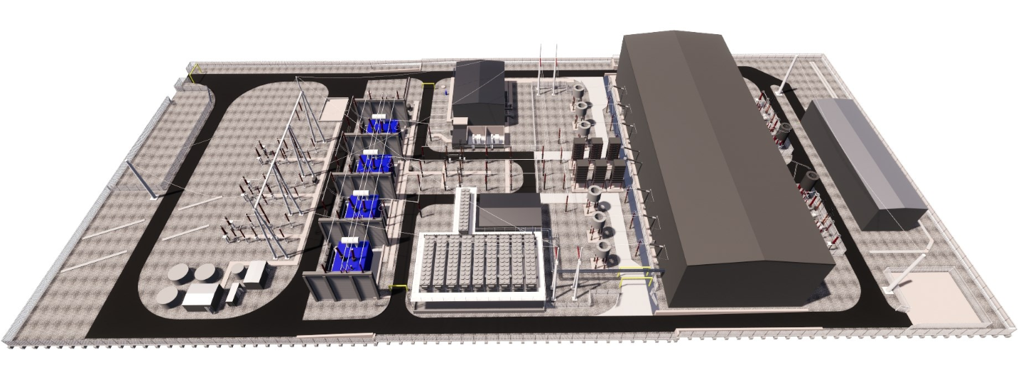
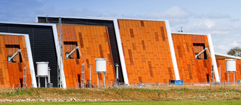
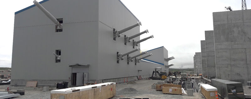
Similarly, DC yards are external in some HVDC substations while at other projects they are placed inside a structure, next to the DC valve hall. In this case, the wall bushings that connect the valves to the DC line can either have their line side exposed to external ambient conditions or these can be entirely indoors (see Fig. 3). Where present, DC reactors can also be placed entirely outdoors and have their bushings exposed to external ambient conditions. Alternatively, the bushings can be installed with the airside of the insulator in the valve hall and protected from ambient pollution (see Fig. 4).
The following discussion focuses on design of external insulation of bushings, both on converter side and DC side of HVDC substation, given the specific voltage waveforms seen as well as possible impact of environmental outdoor factors such as pollution. It is important to note that the creepage and arcing distances calculated in the examples provided below refer only to pollution performance issues. To select the proper insulator for the bushing, it is also necessary to evaluate all other relevant design aspects, including lightning, switching and AC tests, which include altitude correction if the substation is at an altitude greater than 1000m asl. Finally, installation aspects must also be respected in order to guarantee proper clearance distances from nearby walls or other equipment.

Outdoor Bushings at HVDC Converter Stations
Under operating conditions, bushings installed in an HVDC converter station are subject to voltage waveforms that can differ from one another other depending on the following:
• position of bushing in the substation, i.e. DC valve side or converter transformer side.
• type of converter technology and its topology, i.e.: LCC (depending on number of six-pulse bridges) or VSC (symmetrical or asymmetrical topology).
This differentiation is considered in paragraph 3.1.2 and 3.1.3 and also in the Annexes in the IEC standard now under development/revision. In particular, Annex C contains a list of typical HVDC transmission configurations, showing how the DC voltage is reflected on the AC side: for LCC systems this depends on number of six-pulse bridges and position of bushing with reference to these bridges; for VSC, this depends on the symmetrical/asymmetrical converter topologies.
There are a number of different application scenarios:
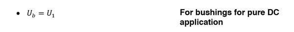
Type a: Bushings for Pure DC Applications
DC bushings subject to a DC voltage with only a small AC voltage ripple (e.g. the bushing on the high voltage side of a DC converter valve (see Figs. 5 to 8).
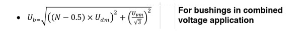
Type b: Bushings for Combined Voltage Applications
A DC bushing subject to a large AC voltage superimposed on a DC bias voltage, e.g. bushings applied to the valve winding side of a converter transformer (see Figs. 8 & 9)
Type c: Bushings Not Subjected to DC
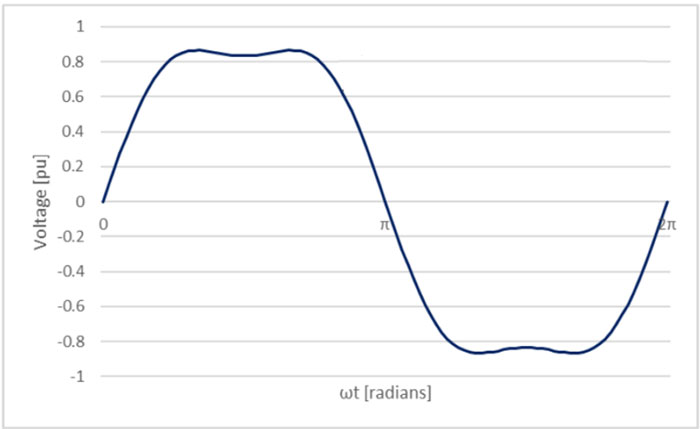
This could be transformer bushings or wall bushings connected to the AC side of symmetric VSC converters (see Fig. 11). Such bushings see a quasi-sinusoidal voltage waveform (see Fig. 10) due to adoption for AC/DC conversion of several discrete voltage levels, as in a modular multi-level converter (MMC) VSC system. Being subject to a voltage stress close to that in AC, their design from the pollution point of view is not considered in this discussion since this is already covered in IEC TS 60815-1, 2 and 3.

Determining Voltage for Bushing Design from Viewpoint of Pollution
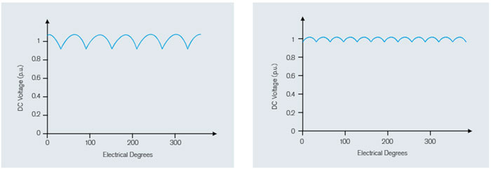
For Type a bushings (i.e. bushings for pure DC applications), the DC voltage dominates even if a mix of harmonics can be present. For example, Fig. 12 depicts idealized voltages across an unloaded 6-pulse bridge and across an unloaded 12-pulse bridge configuration. The base voltage to be used in design of such bushing insulators from the pollution point of view is the rated DC continuous voltage. Peaks due to ripples are not considered.
In a combined voltage application, bushings are subject to voltage wave shapes where complex alternating voltage waveforms superimpose on DC voltages.
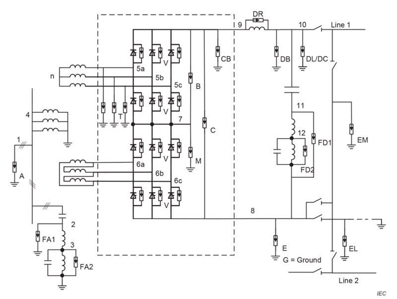
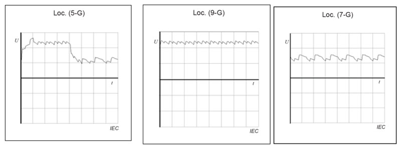
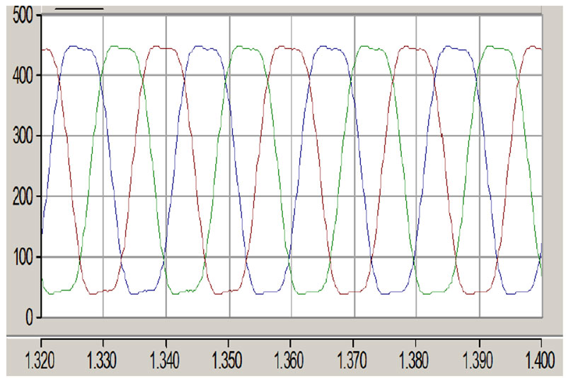
For Type b bushings (i.e. bushings with combined voltage, as in the case of LCC HVDC transmission), continuous operating voltages at various locations within an LCC HVDC converter station could be a combination of direct voltage, fundamental frequency voltage, harmonic voltages and high frequency transients, depending upon location. For example, Fig. 14 shows typical waveforms of continuous operating voltages to earth (G) for a bushing (excluding commutation overshoots) at various locations at an LCC HVDC converter station with two 12-pulse converters in series per pole. Similarly, Fig. 15 shows waveshape for a 12-pulse bridge where C represents line to ground voltage waveform for the top transformer (Y-Y) and D is actual line to ground voltage waveform for the bottom transformer (Y- ∆).
In the case of a VSC asymmetrical arrangement, Fig. 16 represents a typical idealized voltage waveshape at the transformer side: a dc offset is present on a quasi-sinusoidal waveshape.
Peak voltages of short duration, as in Figs. 14 & 15, can be assimilated to overvoltages and are not considered in engineering practice to verify performance under steady state conditions, e.g. as under pollution. In the case of pure AC and DC, design under pollution is not carried out with reference to peak but rather to rms voltage. A more complex case is when combined voltages are present and it is then necessary to define an equivalent voltage stress for design and testing purposes.
For a bushing for combined voltage application, the issue remains whether this equivalent voltage should be assimilated to AC or DC. Experimental research involving small insulator samples has shown that the impact of the DC component on the 50% peak flashover voltage of the insulator under pollution (i.e. V50,hybrid,pk = VAC,pk + V50,DC) is reduced by up to the ratio 40%/60% of the DC component/AC peak voltage. This suggest the possibility of adopting a reasonable threshold level for the DC component, below which use of AC Technical Specifications (i.e. IEC TS 60815-2 or IEC TS 60815-3) to size the insulator under pollution could be carried out in place of using that for DC (IEC TS 60815-4).

Pending additional investigation, however, a conservative design is made (also for combined voltages) with regard to the more conservative DC specification and with reference to voltage Ub, determined as follows (as per the new IEC standard now under development):
with
– U1 the rated continuous DC voltage
with
– Udm the highest DC voltage per valve bridge across each six-pulse bridge for LCC and across the whole converter for VSC;
– Uvm is the maximum phase-to-phase AC operating voltage of the valve windings of the converter transformer on which the bushing will be assembled.
– N is, for LCC, the number of six-pulse bridges in series from the neutral of the DC line to the converter bridge connected to the bushing when mounted on the converter transformer \ wall bushings installed on the ac-side of the converter valve. For VSCsym N is equal to 0.5. For VSCasym N is equal to 1;
Annex E of the updated standard under development contains examples of calculating creepage as a function of bushing position in the substation as well as HVDC converter station layout and technology.

Definition of DC Pollution Classes
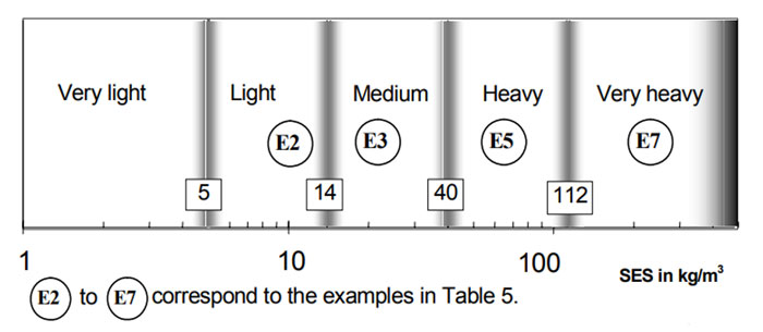
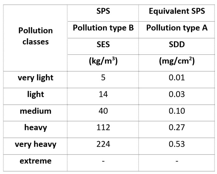
Since pollution classes are not yet defined in IEC 69815-4, the following case examples are based on the pollution classes proposed by Alberto Pigini at a recent INMR WORLD CONGRESS (see Table 1), with the note that in the case of DC these have to refer to measurements on energized insulators.
DC pollution classes cannot be determined based on the indications found in IEC 60815-1 (e.g. Table 3 or Figs. 1, 2 and 3). Rather, these require different estimates because dc insulators accumulate a higher volume of pollutants due to a constant electrostatic field along their length. For example, if pollution site equivalent salinity (SES) for AC is estimated at between 14 and 40 kg/m3 (i.e. Fig. 18 thus defining pollution site severity as medium), the corresponding values estimated in DC would fall between 40 and 112. This would classify the site as ‘heavy’ pollution, assuming a ratio of DC to AC contamination of Kp=2.8.
Rough indications to convert estimates of pollution severity from AC to DC can be obtained in Table 1 of IEC 60815-4. But as pointed out in the same TS, “In view of the large range of possible values for Kp, it is highly recommended to determine the DC site pollution severity by measurements made on d.c. energized insulators, for as long a period as possible and including any seasons likely to result in higher accumulation, in order to get a more precise estimation of the d.c. severity.”
The above values are assumed to be derived from measurements performed on reference cap & pin or small diameter long rod insulators energized under DC voltage.
Evaluating USCD According to IEC 60815-4
Once pollution severity class has been defined, strict determination of creepage distance required is made according to IEC 60815-4. To take into account assumed lower contamination found on large diameter insulators (in accordance with IEC 60815-4), the severity values in Table 1 must be multiplied by a factor, Kd, which takes the effect of diameter on the pollution accumulation into account:
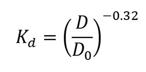
where D0 = 250 mm
Since there are only a limited number of bushings in parallel, the statistical safety factor, Ks (applicable when there are many insulators in parallel), is not considered. Applicable SES can then be determined using the following equations:
• Pollution Type A:
· SDDDC=SDD x Kd
• Pollution Type B
· SESDC=SES x Kd
Finally, required RUSCD can be determined from the following equations:
For Type A pollution:
• Non-HTM materials: RUSCDdc = 110 x SDD 0,33
• HTM materials: RUSCDdc = 65 x SDD 0,25
For Type B pollution:
Non-HTM materials: RUSCDdc = 15 x SES0,33
HTM materials: RUSCDdc = 15 x SES0,25
These equations are applicable to reference insulators (i.e. cap & pin insulators or station insulators with average 250 mm diameter installed at sea level or up to an altitude of 1000m and with a profile close to that used to determine the reference unified specific creepage distance (creepage factor, CF, ratio between creepage distance and arcing distance of about 3.5).
The USCD for bushings is determined, taking into account insulator diameter and installation altitude, according to the following equations:
USCD= RUSCDdc× Cd×Ca
where enhancement coefficient, Cd, is:
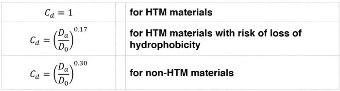
NOTE: Since hydrophobicity of high-grade silicone rubber materials can experience progressive reduction in certain situations, it is advisable to size insulators with silicone sheds as HTM material with risk of loss of hydrophobicity.
The coefficient, Ca, is:
![]()
The above USCD value is applicable for insulators with creepage factor (CF) of about 3.5. Higher USCD may be necessary in consideration of the lower efficiency of profiles with higher CF. However, present quantitative indications cannot be given and have to be based on performance of the specific insulator as determined by laboratory testing. In the following example, influence of CF is considered negligible up to a value of about 4.

Example of Determining Bushing Arcing Distance
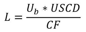
Once USCD is evaluated, arcing distance can be calculated as follows:
Below are examples that report on minimum arcing distances necessary as a function of system voltage and pollution class, considering:
– typical diameters of insulators as a function of system voltages;
– insulators with creepage factors CF=3.
Based on the typical bushing diameters in the following examples, a simplified relationship is assumed between average bushing diameter and rated system voltage, for both polymeric and porcelain housings:
![]()
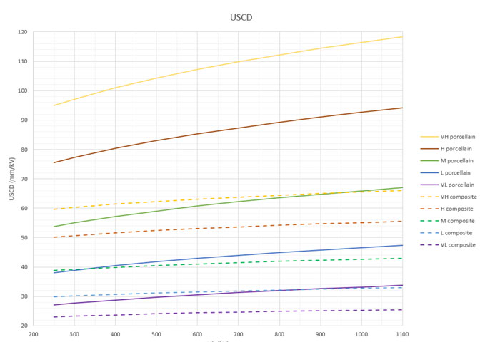
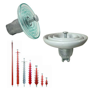
Fig. 19 compares USCD values calculated for ceramic and composite insulators for different pollution classes, from very low to very high. This determination was made considering Type B pollution (simulated in laboratory by salt fog tests). Similar results could be obtained for Type A pollution criteria.
It is immediately clear that higher creepage distances are required for ceramic compared to composite insulators and this difference increases significantly in high pollution sites and with converter station voltage level. For example, in a lightly polluted site, a 300 kV composite bushing insulator requires a USCD of 30 mm/kV while a porcelain insulator needs 38 mm/kV; in a medium polluted environment an 800 kV composite bushing insulator requires around 42 mm/kV while this increases to 64 mm/kV in the case of a porcelain insulator.
The difference in specific creepage distance requirement between porcelain and composite insulators is also due to the lower influence of diameter on USCD in the case of HTM compared to non-HTM materials. As voltage (and consequently diameter increases), the USCD requirement remains almost constant for composite material at any specific pollution level. But in case of porcelain insulators, this increases with voltage/diameter. Therefore, the USCD requirement for a porcelain insulator in highly polluted sites is such that it becomes unfeasible because of excessive length.
Moreover, porcelain insulators are not recommended for DC wall bushing applications since they have a higher risk of flashover under rain. In such situations, part of the insulator remains dry (due to the shielding effect of buildings), resulting in uneven wetting of the ceramic surface due to its hydrophilic property. This can lead to increased field in the dry area, leading to flashover. In fact, application of composite insulator housings for bushings and similar devices has long been applied to successfully resolve flashovers at HVDC stations. These flashovers occurred due to uneven wetting of external insulators, such as horizontally mounted bushings, and this phenomenon was independent of creepage distance.
In general, the arcing distances prescribed by required USCD for both porcelain and composite envelopes in high pollution sites require considering the feasibility of outdoor versus indoor solutions. Indeed, the preferred solution for HVDC transformer bushings above a certain voltage is already indoor installation because of pollution requirements.
Even for outdoor wall bushings, the only solution possible is with composite envelopes in order to limit total bushing length and related mechanical issues. For composite insulators operating in medium pollution environment, 39-43 mm/kV is required while for heavy pollution this becomes 50-56 mm/kV. In the case of very heavy pollution, this requirement becomes 60-66 mm/kV (see Fig. 21). Many HVDC installations these days, sited where pollution is lower than or equal to heavy, require USCDs in the range of 40-50 mm/kV.
Now, with expansion HVDC networks, it may become necessary to build substations even in extremely polluted environments. Choice of voltage levels will then have to consider the feasibility of equipment needs given the applicable pollution requirements. HVDC converter station locations should ideally be sited in areas with the lowest pollution level among all the areas in the project. Alternatively, it may be necessary to opt for indoor solutions to avoid excessive lengths of bushing insulators based on related manufacturing and mechanical constraints.
In principle, lower bushing lengths can be achieved with higher creepage factors but a higher CF would decrease the efficiency of sheds profiles and, theoretically, require higher USCDs. Such choices would have to be verified through testing given that profile parameters under DC reveal that some Creepage Factors can have a much greater effect than under AC.
Conclusions
• Bushings at HVDC converter stations are subjected to different voltage waveshapes depending on location in the substation as well as on the applicable HVDC transmission technology;
• In many situations, the permanent voltage on the bushings is close to pure DC and design is made in accordance with IEC 60815-4;
• In other cases, bushings can experience combined voltages, i.e. AC, DC, and pulsating components, whose shape appears closer to an oscillating than to a direct voltage (pending additional investigation). Conservative design is then made with reference to the DC specification. Adoption of AC voltage as an equivalent voltage for design and testing (as suggested by tests on short insulators), could become a possible future scenario pending further research involving larger, more representative samples;
• High values of USCD are needed for HVDC sites in high and very high pollution environments. This favours use of composite insulator housings and/or indoor installation;
• Widespread growth of HVDC networks may create the need to build new converter stations, even in more extreme environments. Therefore, voltage levels and installation solutions will both have to consider all the limitations linked to design under pollution.
References
[1] IEC/IEEE 65700-19-03, «Bushings fro DC application,» Draft.
[2] «Sofia Offshore Wind Farm,» [Online]. Available: https://sofiawindfarm.com/.
[3] P. Cardano, A. Pigini, M. Sehovac, G. Testin, P. Valvassori, «Converter Transformer Bushing external insulation Design,» in ISH Congress, 2017.
[4] GE Grid Solutions, «The SouthWest Link Transmitting Power and Controlling Voltage with HVDC in Sweden,» [Online].
[5] IEC TS 60815-1, “Selection and dimensioning of high-voltage insulators intended for use in polluted conditions – Part 1: Definitions, information and general principles,” 2008.
[6] IEC TS 60815-2, “Selection and dimensioning of high-voltage insulators intended for use in polluted conditions .Part 2: Ceramic and glass insulators for a.c. systems,” 2008.
[7] IEC TS 60815-3, «Selection and dimensioning of high voltage insulators for use in polluted conditions -Part 3. Polymer insulators for AC systems,» 2008.
[8] Birender Singh Thind, Ajith John Thomas, C C Reddy, «Effect of Voltage Waveform of HVDC Converter Transformer on Lifetime Charachteristics,» in IEEE, 2020.
[9] IEC 60071-12, «Insulation co-ordination – Part 12: Application guidelines for LCC HVDC converter stations,» 2022.
[10] J. Knauel, A. Wagner, R. Puffer, J.M. Seifert, S. Liu, M. Brueckner, B. Rusek, S. Steevens, A. Gravelmann, K. Kleinekorte, «Behaviour of insulators under hybrid electrical AC/DC field stress,» in CIGRE General Session papwe D1_101:_2014, 2014.
[11] A.Wagner, J. Knauel, R. Puffer, J.M. Seifert, M. Brueckner, B. Rusek, S. Steevens, K. Kleinekorte, «Performance of polymeric insulators in hybrid AC/DCoverhead lines under polluted conditions,» in Cigre general session paper D1-112, 2016.
[12] IEC TS 60815-4, “Selection and dimensioning of high-voltage insulators intended for use in polluted conditions.Part 4: Insulators for d.c. systems,” 2016.
[13] A.Pigini, R. Cortina e M. Marzinotto, «Estimating DC pollution requirements: comparison of simplified IEC approach and statistical approach,» in INMR World Congress, 2023.
[14] Y. Solovyev, L. Arevalo, A. Holmberg, D. Gustavsson, «Operational Experience with Composite Insulators at HVDC Stations,» in INMR Congress, 2022.
[15] A. Pigini, «Pollution Design & Testing: Unresolved Issues,» in INMR Congress, 2022.
[16] Working Group C4.303, «Tecnnical Brochure 518 Outdoor Insulation in Polluted Conditions: Guidelines for Selecting and Dimensioning. Part 2: The DC Case,» Cigrè, 2012.