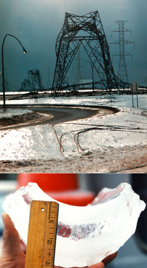
In January 1998 Québec and large areas of eastern Canada as well as the U.S. North-East were hit by a fierce ice storm which combined high winds with prolonged freezing rain. The unusual weather phenomenon created greatest havoc with electricity supply in and around the city of Montréal, where ice accumulation was heaviest – more than 75 mm in some places. Especially hard hit was a region south-east of the city, where the power disruption was near total and lasted for days and in some cases weeks.
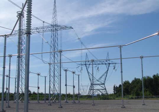
The utility most affected by the ice storm was Hydro Québec and in its aftermath plans were quickly put into place to reinforce its transmission grid against similar future events. One of the direct outcomes was the building of a new 765 kV substation close to the area of total blackout as well as an EHV line linking it with the large Hertel station located outside Montréal.
Although most of the disruptions from the 1998 storm were due to toppled towers, widespread flashovers were reported in at least one major 765 kV substation. These flashovers were due to ice accretions on support insulators which transformed them into virtual cylinders such that creepage distance became essentially the same as arcing distance. With this experience in mind, Hydro Québec began to assess which type of post insulator technology would be most suitable for its Montérégie 765 kV Station in order to protect against catastrophic icing.


Plans to build a new 765 kV substation to reinforce the grid around Montréal and provide an alternative electricity supply to the most affected region began almost immediately after the 1998 event. The original intention was to start construction by March 1999 and to put the new station into service before 2000. However a quick project turnaround was slowed by procedural issues, particularly the public consultation process which had been largely by-passed in an effort to reinforce the network as quickly as possible. This delay resulted in engineering work on the station beginning only at the start of 2002.
According to its Project Engineer, the Montérégie Substation was commissioned in December 2003 and constructed in about 18 months at a then cost of about CA$ 100 million. From a civil engineering point of view, there were not many changes from other such stations in the network which are generally more over-designed from a load point of view than are overhead lines. Indeed, no structures at any of Hydro-Québec’s substations toppled as a result of the 1998 ice storm.


Nonetheless, when planning Montérégie, changes were still made, including reinforcing the portals as well as increasing normal conductor to earth clearances from 26 to 28 m to better deal with sag. Similarly, mechanical stress on structures was reduced wherever possible. Given these precautions, the ice thickness specification for which the station was designed was 65 mm.
One important area of change was in substation insulation, specifically busbar and disconnect switch supports. This change was driven by experience at other Hydro Québec substations during the first evening of the ice storm when large ice accumulations on support insulators created serious flashover risks. Basically, any plans to reinforce the network against the damaging structural effects of icing would also have to take into account the negative impact on performance of electrical insulation.


Flashovers on EHV lines are rare at Hydro Québec and one of the reasons is that insulation on such lines is intentionally over-dimensioned to allow a safety margin whenever circumstances require changing out damaged insulators on a string under live conditions. In this respect, whenever there are extreme climatic conditions that can lead to flashover, post insulators at stations – specifically busbar and disconnect switch supports – become the weakest link in the insulation chain. At 765 kV, for example, the specific creepage of these insulators is about 15 per cent lower than on lines.
Flashover problems at substations proved relatively minor by comparison with what effect the heavy icing from the 1998 storm had on the overhead network. Nonetheless, a decision was still made to look for improved insulation performance when designing Montérégie. Basically, since the decision was made to reinforce the entire network, it also made sense to design the new station’s insulators to offer superior performance under icing.
Achieving improved insulation performance under icing conditions differs significantly from what might be required under pollution and indeed presents somewhat of a paradox. This is because, unlike what might normally be expected, increasing creepage distance alone actually diminishes icing performance if it results in diminished spacing between sheds. For example, insulators at such substations would normally have some 11 m total creepage distance. However, this might mean nothing during an ice storm when what really matters becomes arcing distance given a heavy ice thickness on the insulator. Shed geometry also has minimal impact under such extreme conditions.
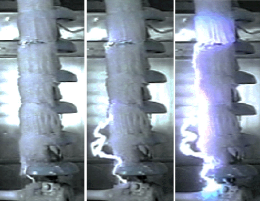

Problems related to icing stem mainly from non-uniform deposition which can result when chunks of ice break off at the start of the melting process. Arcing then starts relatively quickly at the insulator extremity and can quickly propagate into flashover. Risk of flashover is typically greatest just as the melting process begins since water formed at the surface is up to 10 times more conductive than the water originally deposited at time of ice formation. Essentially, contaminants migrate to the surface of the ice and that is why melting becomes so critical.
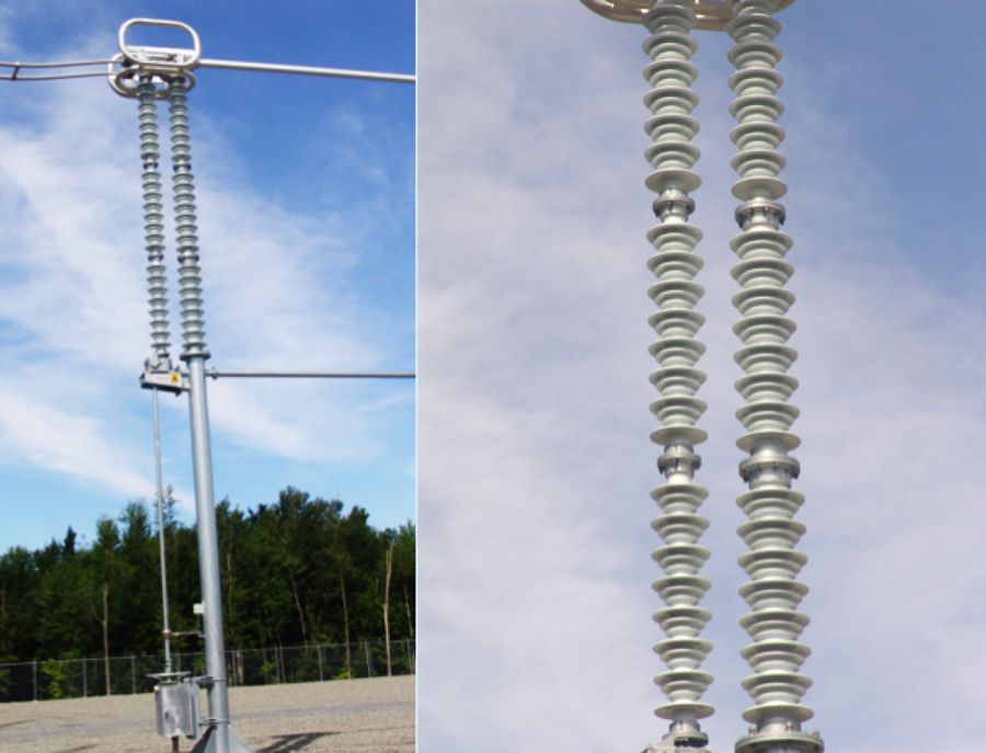
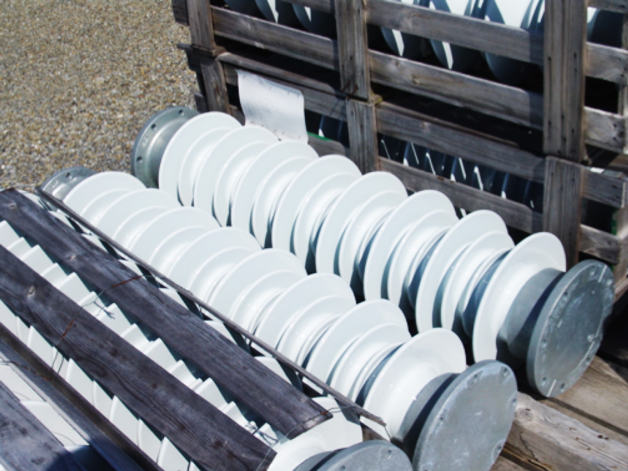
Hydro Québec has employed a variety of designs for its station support insulators, from a standard shed profile with about 50 mm between sheds to a special design which has three alternating sheds and offers much greater distance between the widest sheds. This three-shed profile is expected to offer superior protection against the effects of ice accumulation versus a standard profile however itself becomes basically ineffectual once a critical ice thickness is reached. The critical point occurs when icicles bridge the distance between sheds. Since Montérégie was designed for extreme ice conditions, all possible solutions to this problem had to be considered.
In the effort to determine which type of station insulator would perform best in preventing a flashover triggered by extreme icing, Hydro Québec commissioned research and testing of different types of insulators at the University of Québec in Chicoutimi (UQAC). The test program, which was conducted in specialized ice testing facilities, took place during 2001 and involved flashover testing of a variety of different insulators with arcing distance of 2.7 m – about two-thirds of a full-scale unit at 765 kV. This testing supplemented earlier ice testing conducted by Hydro Québec on insulators with arcing distances up to 0.6 m. Basically, withstand voltage was compared based on the rising voltage method described in IEC 60507. The critical point during testing occurred when the temperature approached 0°C, at which point a thin layer of highly-conductive water would form on the surface of the ice.
One of the insulator types tested was a three alternating shed design of porcelain having a special semi-conducting glaze which allows a small current to flow continuously along its surface. This type of insulator, while not new technology, had apparently been further refined by the manufacturer for applications at another Canadian utility. With this concept, the continuous current flow results in more uniform ice deposition along the insulator, thereby reducing incidence of arcing near extremities under non-uniform ice. While the concept has no real impact on ice accumulation, it does reduce ice dropping off the unit before the critical moment and by dampening the voltage across the gap also prevents arcing near the extremity. Indeed, testing at CIGELE confirmed that the semi-conducting glaze units offered superior voltage withstand which varied from 20 per cent better than a standard shed profile for heavy ice thickness to as much as 30 per cent better at moderate thickness.

Since there was only a small difference in acquisition cost between a standard profile and the three alternating shed design, Hydro-Québec also looked at the potential benefits of increasing arcing distance of the standard glaze three-shed unit by 15 per cent. In the end, a techno-economic analysis of the findings on icing performance as well as of the different costs pointed decisively to the semi-conducting glaze option. This was the case in spite of the concept’s major drawback, namely the power losses incurred. These were calculated to be about 385 watts per insulator which, at the utility’s power cost structure of the time, translated into a per unit cost of about CA$ 2130 over the expected 40 year life of the insulators. According to Hydro Québec engineers, this incremental cost was deemed acceptable given the significant improvement expected in icing performance. Helping in this regard was the fact that semi-conducting glaze units were only about 15 per cent more costly to purchase than equivalent insulators with normal glaze.
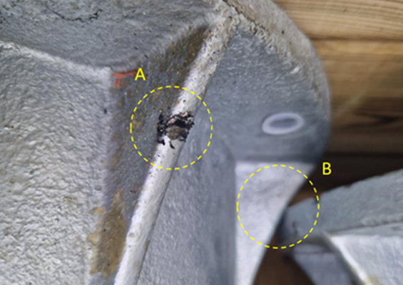
Having made the decision to employ this type of insulator, engineers at Hydro-Quebec now had to deal with the fact that a surface current of 1 mA along a semi-conducting glaze unit is significantly higher than the induced capacitive current normally flowing along a standard glaze porcelain at nominal system voltage. Moreover, given the fact that normal manufacturing tolerances in semi-conductive glaze resistance can be as much as ±30 per cent from one unit to another, surface current along a single support column made up of three insulators could conceivably fluctuate by as much as 60 per cent between different units. This would mean that the two intermediate flanges, normally having a floating potential due to the resistive glaze of a porcelain unit, could now have some fixed potential.
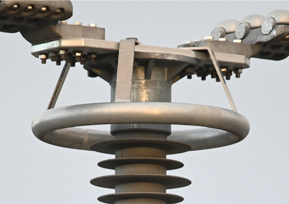
This issue became especially relevant in the case of supports for disconnect switches where two columns – one fixed and the other turning – are in close proximity to one another. If surface current in each column can vary by as much as 60 per cent due to tolerances in manufacturing the semi-conducting glaze, arcing problems can be created between the hardware of adjoining columns due to the resistive divider effect. To resolve this issue, each insulating column at 765 kV would have to be ‘balanced’, i.e. made up of insulator units with basically the same deviation from the standard manufacturing tolerance. These units were then referred to as Types A, B and C. Not only did they have to be matched up during the construction phase of the new station but also spares had to be kept and labelled suitably to ensure that any future replacement respected the need for matching the units in any one support column.
Looking back on the entire testing and decision-making process for 765 kV support insulators at Montérégie, Hydro Québec engineers admit it was a challenge since it was the first time they had to find a solution to potentially extreme icing problems. About CA$ 1 million was eventually spent on the station’s circa 260 units of 765 kV insulators – a higher amount than originally budgeted based on past experience. At the same time, purchasing the insulators from a different manufacturer than the disconnect switches required maintaining good co-ordination between these two suppliers.
The 1998 ice storm provided an important lesson in what can go wrong when unexpected weather extremes occur. Hydro Québec has since applied the experience gained with the types of support insulators from this project during retrofits elsewhere in the grid and in planning for new substations in northern Québec.