Power system projects with ‘High Strength’ within their scope typically receive special attention since high strength insulators have the potential to improve project efficiency through shorter duration and lower total cost. But achieving this efficiency requires going beyond traditional thinking in line design and studying new solutions. The next challenge is to verify that these will indeed work and that the new approach is worth the effort.
This past edited contribution to INMR by Edward Niedospial, Technical Director Transmission at MacLean Power Systems in the United States discussed how insulator applications can be improved to achieve higher capabilities and how these can be tested and validated.

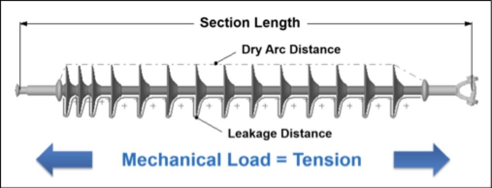
Suspension & Tension Insulators
Mechanical loading of suspension insulators is straightforward and definitions of Specified Mechanical Load (SML) and Rated Tensile Load (RTL) are well understood and also easily quantifiable. Regardless of application, the primary load applied to an insulator is tensile. Moreover, for whatever the specified SML rating, an insulator is not limited by section length. Testing can then be completed as part of the manufacturing process in the factory or at a 3rd party laboratory where test set-up is not difficult and the testing process is standard.
Maximizing tensile performance of a suspension insulator is a function of increasing rod diameter, upgrading end fittings and optimizing compression of end fittings onto the core rod during crimping. Indeed, one of the key elements during crimping is achieving the highest possible tensile output yet without cracking or otherwise overstressing the rod. While 30 klb and 50 klb SMLs have been among the most used ultimate strengths for polymer insulators, suspension applications can actually go up to 120 klb SML and beyond, if required.
Tensile Ratings
SML = Specified Mechanical Load = Ultimate rated tensile load for an insulator.
RTL = Rated Tensile Load = Working tensile load for an insulator in service. (Note: Service conditions should include safety factors for ice and wind loading.)
Tensile Failure Load = TFL = Load at which the insulator fails during tensile loading by one of 3 possible failure modes:
1. End fitting pull off
This is the most common failure mode and the one that can be controlled and predicted as a function of the crimping process during production.
2. End fitting break
This is the next most common failure mode, with ball type end fittings potentially having the lowest breaking loads. The end fitting limit is directly tied to what specific end fitting type is being used and also by the standards that govern that design (e.g. ANSI, IEC, CSA, etc).
3. Rod shatter
This is the least common failure mode, i.e. failure of the core rod in tension. The limit of the rod is a function of its diameter.
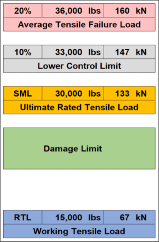
Lower Control Limit = A design limitation imposed by the manufacturer as part the process of validating the insulator’s tensile rating. This is typically supported and defined by some form of Statistical Process Control (SPC).

When validating SML for a suspension application, data from tensile tests should provide a range of failure loads. The wider this range, the less in control is the manufacturing process. The goal for any manufacturer would therefore be to have a tighter range of failures, which is evidence of a process that is in control.
Once average failure load is defined, SPC can be used to determine the lower control limit for that insulator and manufacturing process. This is where there are critical questions:
• What percentage above the SML should the lower control limit load be?
• Is this defined or addressed in a standard?
Technically speaking, a tensile validation test would be considered ‘passed’ if the failure load is just 1 lb over SML rating. But this would not be ideal since it leaves little room for error during manufacture. There should ideally be some design safety factor included in this process.
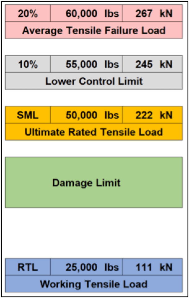
Fig. 3 shows that average failure load is assumed to be 20% above the 50 k SML and that the lower control limit is 10% above the 50 k SML. These values were selected at random for reference and discussion.
Damage limit for an insulator is a function of the tensile failure load, usually ranging from 75% to 85% of the lowest TFL. It is not a function of the SML rating. Ideally, the damage limit should be near the SML rating and also a safe distance from the RTL rating.
Example: The damage limit for a 60,000 lb. TFL
• Assume lowest tensile failure load = 57,000 lbs.
• 75% of lowest TFL = 43,000 lbs.
• 85% of lowest TFL = 49,000 lbs.
It could then be safely concluded that this 50 k SML insulator could withstand an extreme load event of up to 40,000 lbs. without causing damage to the insulator. If considering a new load rating be added between SML and RTL, this might be called the TWL = Tensile Withstand Load.
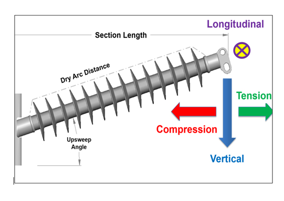
Cantilever Loading of Post Insulators
Whereas tensile loading is straightforward and simple, cantilever loading is not, with many layers of complexity. Again, there are ultimate and working ratings expressed respectively as SCL (Specified Cantilever Load) and MDCL (Maximum Design Cantilever Load). But this is where all similarity to suspension mechanical loading ends and where cantilever loading becomes complicated.
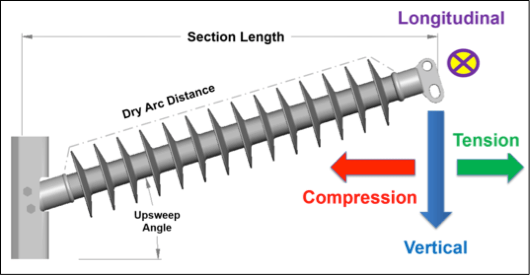
Line post and braced post insulators are not selected by SCL rating or working load. Rather, mechanical rating of a post is limited by section length such that, as a post increases in length (voltage), its ultimate cantilever rating is reduced. Conversely, as a post is shortened it gains mechanical strength but also loses electrical capability. Therefore, when selecting a post insulator, there needs to be the right balance between mechanical and electrical performance.
Mechanical rating of a post is impacted by type of end fittings and connection base. Both are part of standards but not so well defined as the Go/No Go criteria used for tension insulators. These variables aside, the ‘Load Curve’ or interaction diagram is by far the most complex part of a post application. Unlike a tension insulator that withstands a single tensile load no matter the application, line posts and braced posts are subject to a variety of combined loads, comprised of vertical, transverse (compression and tension), and longitudinal loads. The purpose of the load curve is then to consider these various load conditions and provide some Go/No Go criteria for that post insulator. All required loading conditions must fall on or below the MDCL (working) curve. Any load above the MDCL has the potential to cause issues and should be reviewed closely before proceeding.
No single cantilever test validates the ultimate and working ratings of a post. For example, a combined vertical and compression load will have a lower buckling limit than will a combined vertical and tension load. Each of these load cases will therefore have different results with regard to SCL and MDCL. Testing can be completed at the factory for most line post applications along with some braced post applications. However cantilever testing cannot be completed as part of the manufacturing process. Fortunately, various 3rd party test laboratories are able to perform cantilever testing. Some may be limited to single vector load testing (i.e. the traditional test method) while others have the capability to test multi-axis loading, which provides a better representation of actual load conditions an insulator can be exposed to in service.

Load Curves / Ratings / Validation
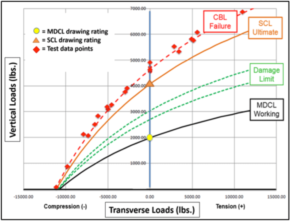
SCL and MDCL ratings on line post drawings are single load conditions on the load curve. Fig. 6, for example, shows that the point where each curve crosses the chart’s Y-axis is the rating provided on the drawing. These ratings are vertical loads with zero transverse load and no longitudinal load.
Transverse loads on the negative side of the chart are compression loads and combined compressive loads take away from a post’s cantilever capacity. Transverse loads on the positive side of the chart are tension loads and, on this side, a post has more combined load capacity. When designing a transmission line with posts, relative to transverse loading, it is better to have the posts aligned such that the conductor pulls away from the tower (in tension) versus pulling into the tower (in compression).
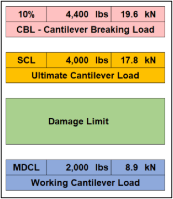
[This table & curve are for reference only to show relationship between CBL – SCL – MDCL. CBL percentage is assumed].
The MDCL or working cantilever curve is 50% of the ultimate curve or SCL. However, there are cases where a customer requires that the MDCL be 40% of the SCL, which is a more conservative value for the working curve. Adding this safety factor to MDCL rating could for example be because there is no defined relationship between CBL and SCL. The CBL loads (cantilever failures) should be some percentage above the SCL and not right on the edge of the SCL, e.g. 1 lb. higher. If the CBL were to be defined and required to be 10% greater than the SCL rating, there would be no need to put a 10% safety factor onto the working curve. The damage limit for a post is also a function of the CBL and ideally would be closer to the SCL than to the MDCL. A post can be subject to more peak load events due to ice and wind. If applied loads are already at the boundary limit, such spikes above the MDCL could diminish the post’s original integrity. If these events are frequent, the result could be post fatigue.

Maximizing Cantilever Applications
A line post insulator is limited by section length such that the longer the post the bigger the core rod diameter needed to withstand the cantilever loads. While it is feasible to use large diameter posts (e.g. 3 or 3.5 in.) for longer post applications, rate at which the MDCL increases is not proportional to the rate at which costs increase. It is at this point that transition from a line post to a braced post makes sense since adding a brace to a 2.5 in. post can provide up to 7 times more cantilever capacity yet with minimal increase in cost for the assembly.
Moving from line post to braced post is therefore one way to maximize cantilever applications. However, a braced post assembly using traditional line post hardware (i.e. base and end fittings) may be limited by the hardware. Typically, these fittings and bases are designed for lower line post ultimate loads and not for the much higher requirements of a braced post. Maximizing braced post cantilever capacity will therefore require upgrades to the base connection as well as to the strength of the line end fitting. As such, in any maximized braced post design, all potential limitations are duly considered and the resulting limitation of the assembly should be the buckling limit of the post. Too often, there is overemphasis on modulus of elasticity and K-Factor of the rod whereas it is in fact the hardware used by different insulator suppliers that drives variability in load ratings and load curves much more than the rod.
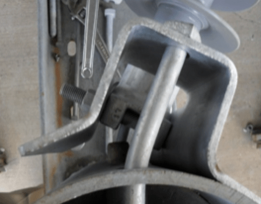
The base is the most critical part of any braced post application since it transfers the combined loads of the conductor through the post into the tower. Traditionally, bases have not been designed for such higher braced post loads and are therefore more susceptible to deformation from stringing and longitudinal loads.
To obtain maximum load capacity from a braced post insulator, the base connection to the tower should be fixed and as close to rigid as possible.
The base itself should be low profile and made from stronger materials such as high grade of steel or of thicker cross-section so as to match the loading expectation of the braced post application. The bolt circle is an ideal tower end fitting for these more robust applications.
The line post end fitting, in this case a standard line post drop tongue, is the weak link of a traditional braced post assembly since this fitting does not have sufficient tensile strength to withstand higher braced post combined loads. This deficiency is only compounded by the fact that pulling angle changes the breaking limit of the fitting. While a fitting has greatest strength when both ears are pulled straight apart, if both ears are instead being pulled at angles breaking strength decreases as angle increases. Maximum performance of any braced post can therefore only be realized if the limitation of the line end fitting is overcome using a higher strength adaptor bracket (best if mounted to a bolt circle end fitting on the post).
The brace insulator primarily holds vertical loads and some of the transverse loads. Brace capacity can be maximized by increasing the SML rating of the suspension insulator. The brace insulator will rarely, if ever, be the limitation for a braced post. It is unlikely to ever be loaded to the point of breaking since the rod or end fitting will likely fail long before the brace.
Now, with a new base, line end connection and increased SML brace, the final component to upgrade is the core rod. As mentioned, when the limits for all the individual elements of a braced post are equal, the assembly will be limited by rod buckling:
• The post in a braced post application primarily withstands compression and longitudinal loads;
• The post is most resistant to compression when applied at zero-degree upsweep;
• Buckling limit is a function of both rod diameter and post section length. As post length increases, so too must its rod diameter.

Testing & Validation for Braced Post
Testing each individual component is essential and the following are individual tests for the braced post:
• Base – Longitudinal load resistance [stringing, service, broken conductor];
• Brace Insulator – SML tensile testing;
• Brace Hardware – Tensile test;
• Bracket – Fixtured cantilever test to validate tensile strength at various angles pulls;
• Post – Deflection and compression tests for a range of lengths and rod diameters.
Values from individual component testing need to be part of the combined load curve to establish the boundary limits. All these values go into a buckling equation, which not only drives the formation of the curve but also considers the variable geometry of the braced post (section length, assembly height, upsweep angle, etc.). Validating the load curve requires full-scale testing of the braced post assembly, testing a range of combined load cases that cover the extreme loads on the ends of the curve as well as several load cases along the curve between these extreme loads.
Testing an optimized braced post:
• The braced post assembly should be set up to match the field application, matching the pole geometry as closely as possible with respect to bolt mount patterns and pole OD at the base connection.
• The same bolts (type and grade) to be used in service should be used in testing.
• Multi-axis testing – the test should have at least 3-axis testing to simulate vertical, transverse, and longitudinal loads as these would be applied to the braced post in service.
• Testing should include longitudinal restraint to simulate the stiffness provided to the post tip by the conductor. An unrestrained braced post will be free to ‘walk’ in whatever direction the combined load dictates. But in service the end of the post is not free to move at random. The conductor adds to the equation.
• Each test case would take 3 individual loads to a service load condition and then add compression to simulate wind loads or additional vertical to simulate ice loads.
• Each test would be pulled to failure.
• During testing, as the post bows and ultimately buckles, the resulting stress will impact base and mounting bolt performance as the braced post approaches its CBL.
In the end, the objective of testing is to collect data points that confirm that the SCL rating of the assembly is accurate, giving added credibility to the calculated load curve. Deflection data will help define when the loads are approaching a damage limit. The line post rod will remain essentially rigid throughout most of the test sequence. But as the rod approaches its buckling limit, the post transitions from rigid to flexible, quickly driving the assembly to a failure of the rod, base or bolts.
The CBL for a high strength braced post is when something breaks in the assembly. Often, this will be bolts that mount the post to the tower. The SCL rating for that same high strength braced post should be at the point before the post transitions from rigid to flexible.

Conclusions
Whether considering suspension, line post or braced post insulators for high strength applications, the keys to success include:
1. Know and understand the current limitations of the application at hand. Something cannot be made stronger without first determining what can make it weak.
2. When a limitation is reached, determine what upgrade is needed to overcome that limit.
3. Keep looking for what more some component should do.
4. Do not be influenced only by how things have been done in the past since these may inhibit real progress.
High strength applications offer new opportunities and could be the solution to reduce project duration, lower costs and improve reliability of a transmission line.