Although transmission line arresters (TLAs) have been used for decades to increase reliability and availability of transmission lines, some grid operators are still reluctant to apply them on their networks. This is due to a variety of factors including lack of confidence in TLA technology in general, past negative experience or simply not being convinced by the arguments for such an investment.
This edited past contribution to INMR by Philipp Raschke, R&D Manager at Tridelta Meidensha in Germany, aimed to build confidence in line arrester technology, especially of the non-gapped type (NGLA). It provides solutions to existing difficulties and also offers guidance on construction for NGLA designs, suitable quality assessment procedures and best practices for their application on transmission conductors and towers. Finally, results of a specific mechanical investigation are discussed as part of standardization work for line arrester standard, IEC 60099-11.
The fact that IEEE and IEC are now co-operating on a harmonized standard exclusively for line arresters bodes well for improvement in line arrester technology as well as product quality. In the past, line arresters received almost no attention in international standardization, in spite of the growing number of such projects worldwide. However, starting in 2011 externally gapped line arresters (EGLAs) – one of the two versions of TLAs – received a separate IEC 60099-8 due to their air gap. NGLAs were given attention for the first time in Annex H of IEC 60099-4 Ed.3.0.
A large number of NGLAs are now in use due to growing application on networks as well as at increased operating voltages. Given this, it is perhaps no surprise that there have been reports of failures of different brands due to the lack of standardized specifications for quality. In particular, there have been reports of mechanical problems due to faulty installation or poor quality hardware components and designs. Reported electrical failures due to insufficient product design or unsuitable arrester selection have also been discussed in technical reports and papers by TSOs worldwide.
It is therefore all the more important that both manufacturers and users of NGLAs adhere to certain practices. On the one hand, standard guidelines should prescribe the classification and testing of NGLAs for manufacturers while there should be proper practices for arrester selection and installation by users.

Stress Factors & Real World Issues
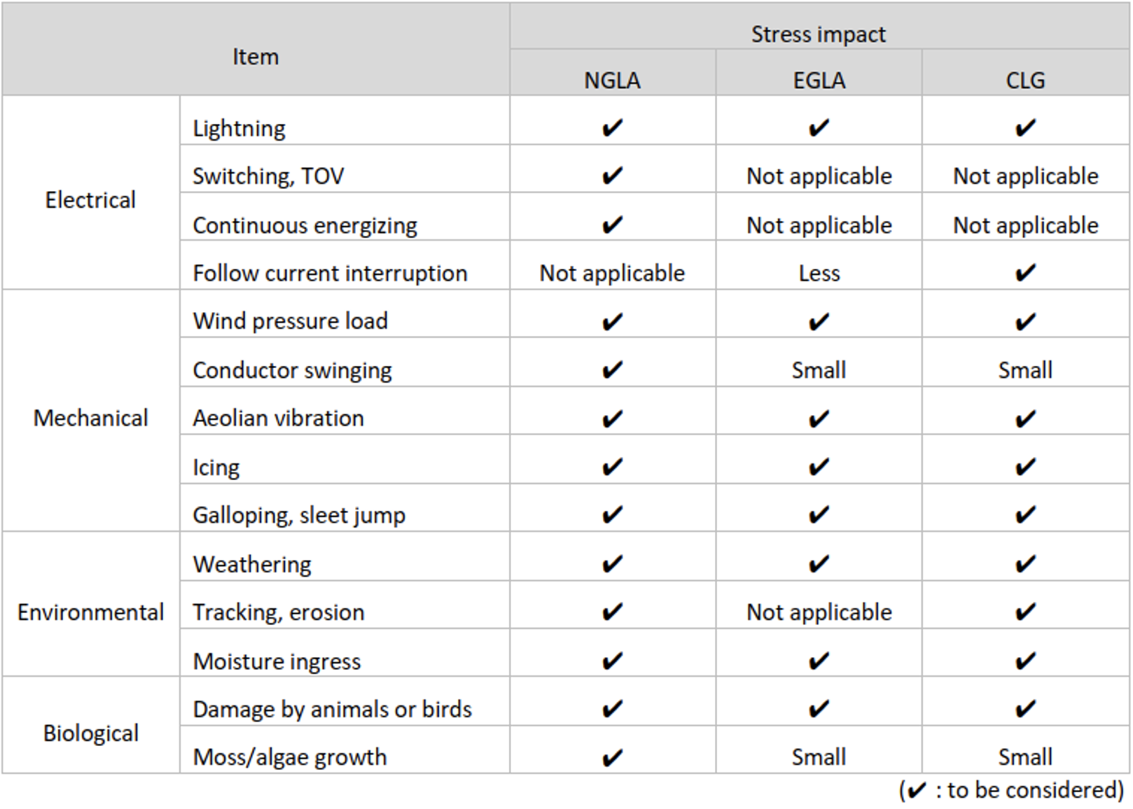
Problems with application of TLAs can arise for a variety of reasons, usually electrical or mechanical in nature or caused by environmental influences. Compared to EGLAs, NGLAs are usually exposed to much harsher environmental conditions during their service life. Fig. 1, taken from a Table in Cigré Paper 855, for example, offered an overview of possible (but not exclusive) stress influences.
Similarly, types of defects and resulting phenomena observed in recent years have been reported in a Cigré C4.39 survey. Worldwide, there is now also much more service experience. Fig. 2 shows the main defects that can result from the stresses shown in Fig. 1.
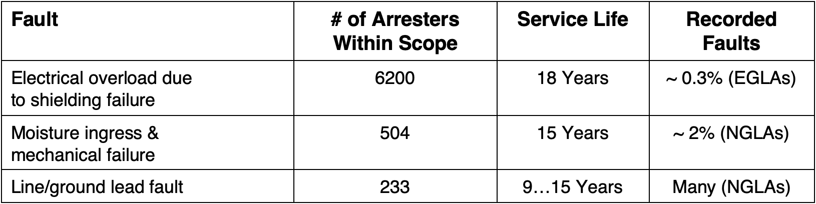
The following sections examine these fault cases, particularly mechanical faults.
1. Electrical Overload
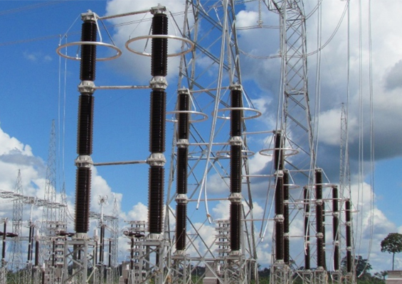
NGLAs are often used for line sections and on structures where there is increased lightning density. Insulator flashovers and resulting power outages are then the major problem. On well-shielded lines, reverse flashovers with negative polarity are assumed with moderate amplitudes and charges falling in the range ≤ 30 kA and ≤ 0.3 C. NGLAs with small varistor diameters are preferred in such cases. In the rare case of shielding failure, higher energies and charges can occur in an NGLA. Indeed, Cigré TB 855 concluded that NGLAs comparable to the highest station classes would have to be used to withstand such rare yet still possible electrical loads.
Moreover, in contrast to an EGLA, the NGLA is exposed to continuous leakage current due to its electrical connection between conductor and ground. Overvoltages cause energy input and sudden temperature increase in NGLAs during the discharge process. Moreover, temporary overvoltages cause high power dissipation and associated heating in the arrester. If both phenomena occur simultaneously, the NGLA can enter a temperature range where more heat is converted in the arrester than its insulation housing can dissipate to the surrounding air, thereby leading to thermal runaway and ultimately to short circuit and breaker operation. While disconnectors, connected in series with the arrester, disconnect the NGLA electrically from the line in the event of overcurrent to ensure successful re-closing, these do not normally react quickly enough to prevent thermal runaway of the arrester and tripping of the line protection.
If all such cases could be accepted for mechanical and economic reasons, a progressive way to be taken in selection of arrester class and tower allocation would then be to choose comparably low arrester classes. It would then be advisable that manufacturers at least test their NGLAs according to the specified classes and requirements in IEC 60099-4. In particular, specific NGLA specifications regarding use of 200 µs pulses to cover multiple lightning strikes from IEC 60099-4 Annex H, ensure that arrester designs will also comply with their specified values in service. Nonetheless, due to the statistical behavior of lightning strikes, exceeding the high current pulse capability, charge transfer capability and energy absorption capability of the arrester can never be completely excluded.
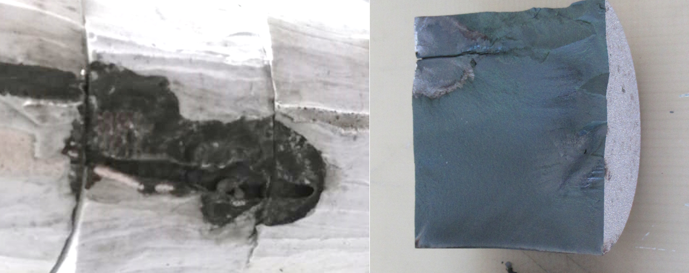
Punctured varistor due to excessive charge (right).
Selection of appropriate arrester class and associated electrical values as well as ideal positioning of arresters along the line will likely remain one of the most important responsibilities of the transmission line engineers.
2. Moisture Ingress
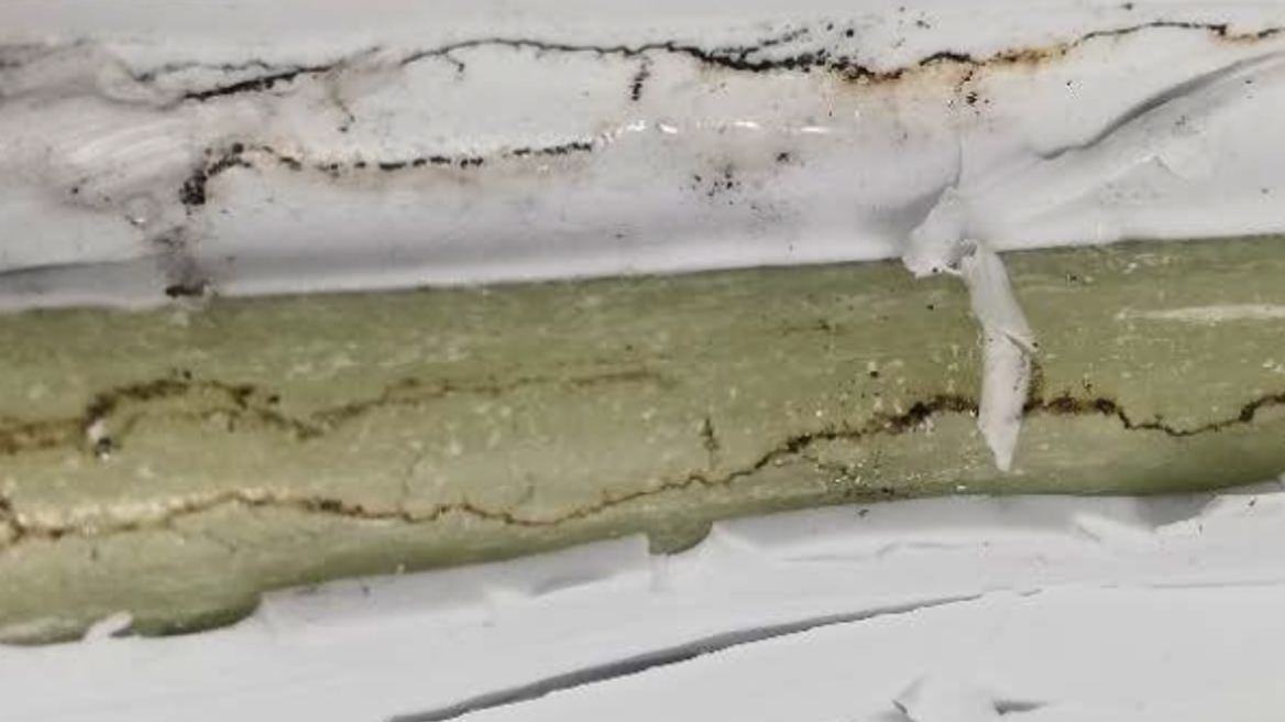
Moisture ingress is perhaps the most common cause of loss of insulation capability in a surge arrester. This leads to internal partial discharges, creeping material erosion, oxidation, internal leakage currents and thus to increased power dissipation and heating. In severe cases, the result is short circuit of the active part or of insulation components.
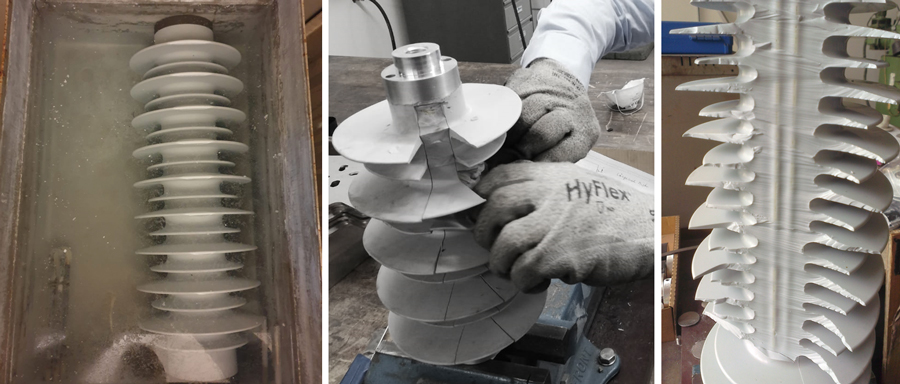
Failure due to moisture ingress is not a phenomenon that occurs exclusively due to a failed sealing system in porcelain arresters. Polymer-housed arresters can also suffer from problems due to moisture ingress, quite apart from the classic failure of the sealing system in the flange area. Fig. 5 shows the most commonly used polymer designs and insulation technologies in for today’s line arresters.
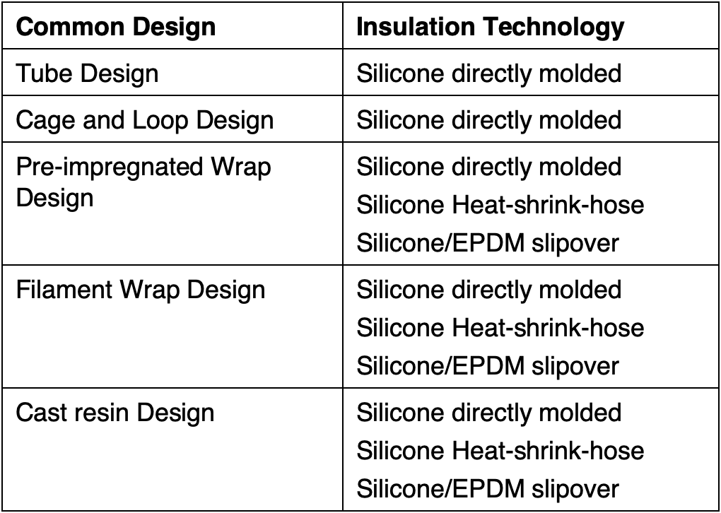
Tube, cage and loop type designs rely on direct molding, primarily with silicone, due to their irregular mechanical structural elements. Meticulous cleaning and surface activation, thorough primer application and blister-free molding are therefore all key processes that ensure complete adhesion of the silicone to all mechanical and active elements. Errors in this process will directly affect silicone adhesion. Since silicone is permeable to water dissolved in the air, under high relative humidity water will condense within a few weeks at any junctions between the silicone and the active parts or insulation components that feature poor adhesion. Since line arresters are continuously exposed to harsh weather conditions, arresters with such defects often fail.
Suitable measures for determining failure-free silicone processes include:
• Water immersion test according to IEC 60099-4 cl. 10.8.11.3.2 as sample test;
• Pull-off test as sample test;
• Leakage test acc. to IEC 60099-4 cl. 8.13, at best the helium leakage test as a routine test.
When using silicone heat-shrink hoses on pre-impregnated designs, a meticulous priming process plays a major role, as important as blister-free application of the ‘pre-preg’ matrix to the active part of the arrester. The key in this case is to avoid any air enclosures and to properly bond the silicone tube to the ‘pre-preg’ surface so as to achieve freedom from risk of partial discharges and not create any voids for water to accumulate.
When using silicone or EPDM molded parts, a simple slipover technique is often used in combination with the ‘pre-preg’ wrap or closed filament winding designs. Silicone grease is then usually used to seal the active to the molded part with no gaps. In the case of filament wound arrester designs, a great deal of mostly hydrophilic silicone grease would have to be used due to the many irregular surfaces. Such slipovers are therefore rarely used since the seal cannot be reliably guaranteed. Rather, modern filament winding cores are usually directly over-molded with silicone to achieve good adhesion and complete filling of the undercuts in the winding pattern.
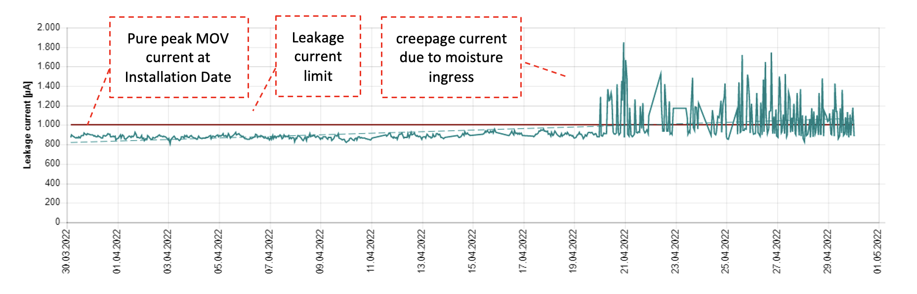
In order to detect possible moisture ingress during time in operation, it is recommended to equip an NGLA with a modern monitoring device which is able to record and evaluate leakage currents (see Fig. 8).
Mechanical Defects & Recommendations for Design & Testing
Mechanical defects on NGLAs originate from different sources and depend greatly on the way they have been mounted. The following three types of installation are most common:
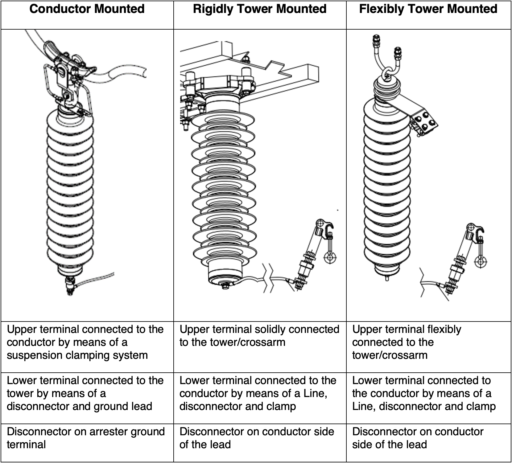
The conductor-mounted installation is most frequent since lines are often retrofitted with NGLAs to improve performance. Moreover, the arresters can be mounted at some distance from the tower, regardless of tower geometry. As such, they normally maintain required clearances even if the disconnector operates and the ground lead hangs down. But such mounting exposes these arresters to all types of conductor movement. Specifically, slow vibration (galloping) and fast vibration (aeolian vibration) cause fatigue fractures in components of the clamping system. This requires robust component design and securing all moving parts of the clamping system.
In the case of a rigid tower installation, the arrester is mechanically de-coupled from the conductor via the line so that no forces are transmitted from conductor to arrester. Rather, only the lead and the connecting elements and disconnector can be subjected to mechanical loads. Nonetheless, the arrester is still subjected to a bending force during gusts of wind, depending on their speed and arrester geometry. Impacting wind forces also cause the arrester to vibrate at its resonant frequencies.

Flexibly tower-mounted NGLAs are de-coupled from the transmission line conductor and thus are not affected by aeolian vibration. In addition, they do not suffer from continuous resonant vibration due to wind gusts since their flexible joint de-couples the arrester from its solid base. The arrester rather swings due to continuous wind or wind gusts. The mounting joint should therefore be wear resistant and line leads should be long enough to permit arrester movement without tension on the lead.
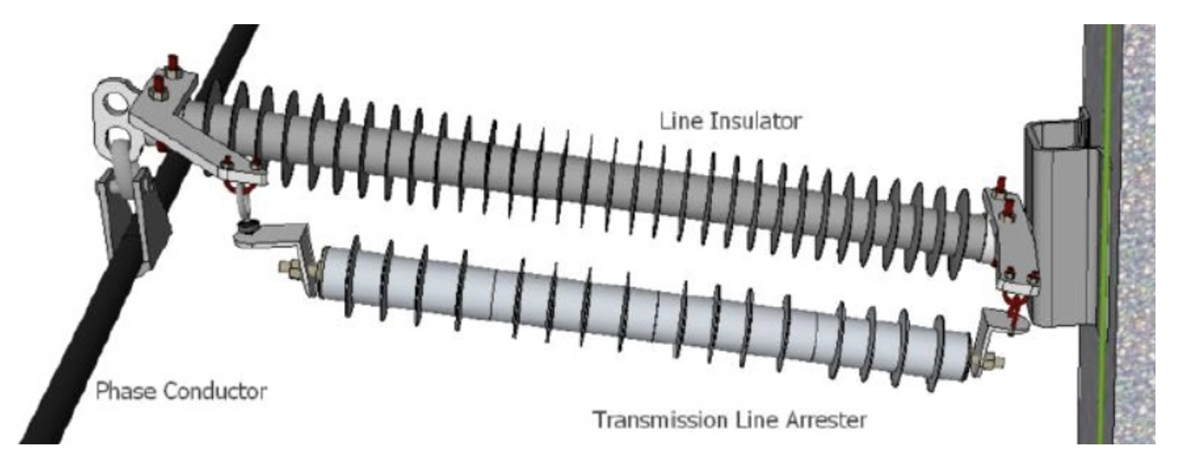
NGLAs that are rigidly suspended to both sides of a line insulator are a special case. The insulator must be strong enough to safely hold the weight and movement of the conductor over its entire service life without any critical movement of its own. This way, no mechanical demand should arise on the arrester, even in the event of conductor vibration.
Mechanical Defects on Clamping System Due to Aeolian Vibration
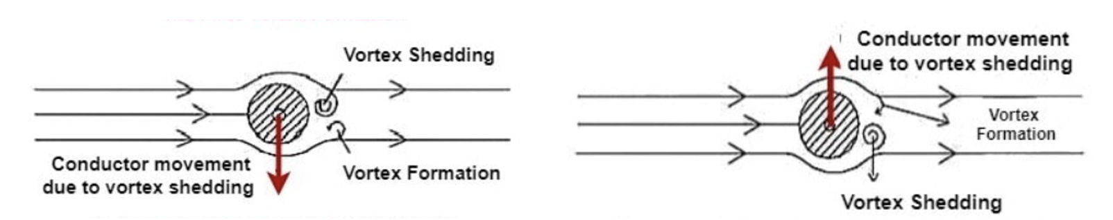
Defects in the clamping system of conductor-mounted NGLAs usually occur due to galloping or aeolian vibration. Galloping is described as wind-induced slow conductor vibration with high amplitude whereas aeolian vibration is fast vibration with small amplitude. Since galloping occurs only under certain climatic conditions, this type of conductor vibration is considered comparatively rare. As such, the focus here is placed on the almost permanent aeolian vibration that arises due to the vortex generated by wind in the area behind the conductor (as shown in Fig. 11).
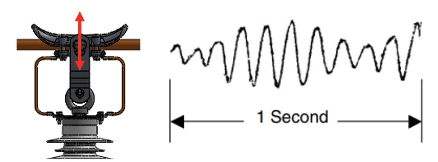
In practice, dampers are used to reduce vibration of the conductor. However, due to design, dampers are only effective in limited ranges of vibration frequency. Expected frequency range is between 3 and 150 Hz and amplitude is expected to be about the diameter of the conductor. This amplitude and frequency range is sufficient to move the mechanical components of the NGLA’s clamping system within their degrees of freedom and tolerances with several million cycles.
Although there are many different arrester manufacturer solutions for clamping systems worldwide, there are no uniform regulations for their design and testing. This makes it difficult for users to completely avoid risk of typical defects on NGLA clamping systems. In general, it is recommended to use only high quality, proven components from standardized power line hardware.
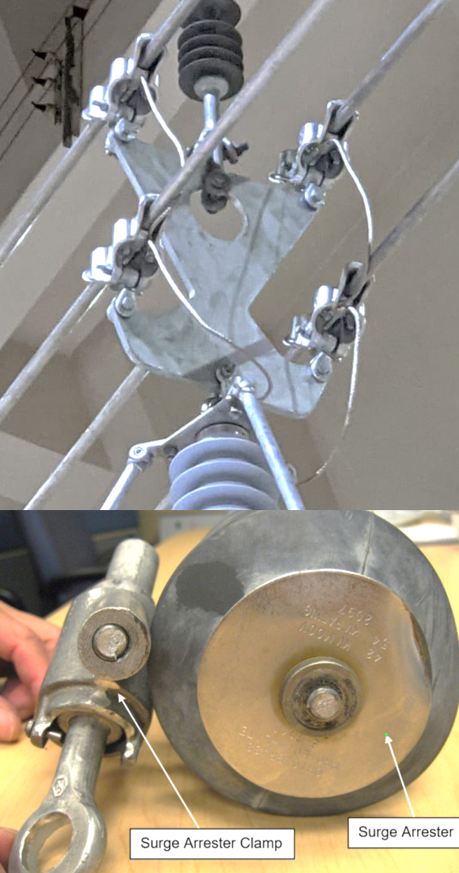
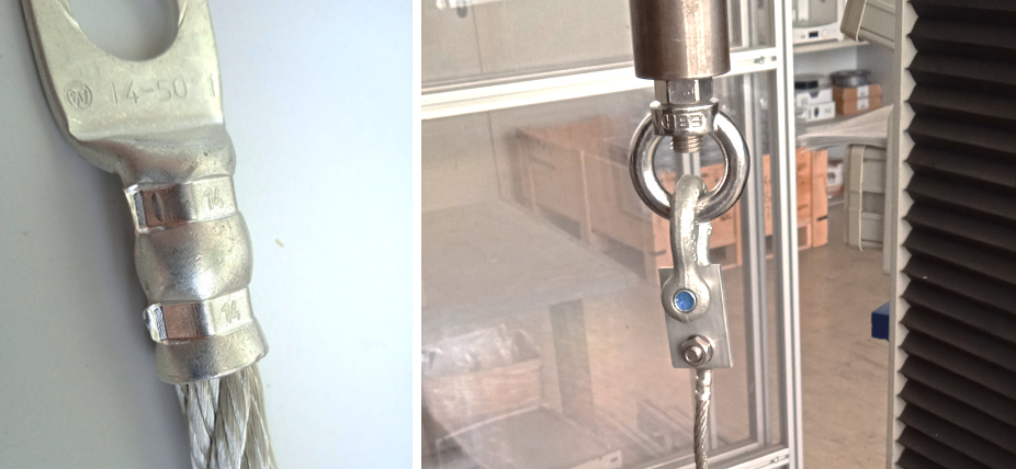
The connection between arrester and conductor should be free to move in any horizontal direction. This is why a combination of ring nut, shackle and conductor cable clamp is usually chosen. For multi-conductor bundles, matching yoke plates with multiple clamping systems are used to distribute the force to all conductors. Bolts should always be secured with nut and additional cotter pin and in no case with thread locking adhesive. Short-circuit leads should be made of flexible, braided tin-plated copper. Terminals in UHV applications should ideally be corona free designs (see Fig. 13). Moving, mechanically stressed parts (such as shackles, bolts and ring nuts) should be made of strongly hot-dipped galvanized steel or of high quality stainless steel. Given such practices, failure of the clamping system is unlikely.
However, proof of performance can only be verified through practice or by means of a test. So far, no vibration tests on NGLAs have been prescribed or are standardized. This has resulted in an effort to include vibration tests on NGLAs by PT11/IEC60099-11 Working Group. In the case of conductor-mounted installation, the moving components of the suspension system need to be tested but not the arrester itself. The goal is to introduce a vibration motion into the clamping system that is close to reality, with the arrester applying a tensile force to the clamping system.
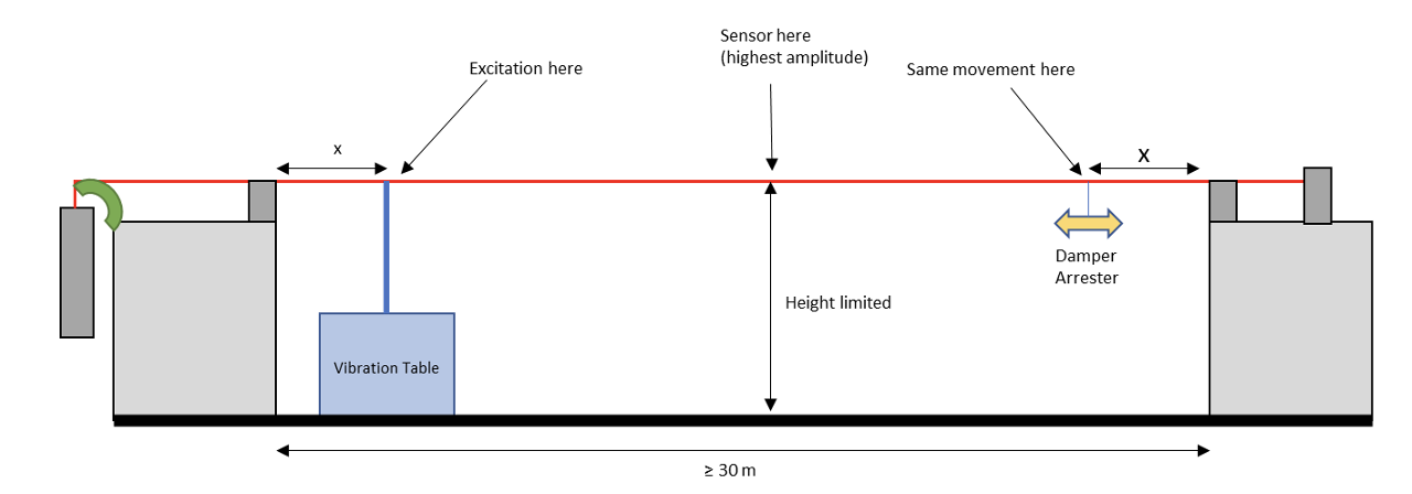
Similar to the method as per IEEE 563, a comparable test for vibration dampers according to IEC 61897 has already been considered as a representative test for NGLAs with regard to aeolian vibration. For this purpose, a section of conductor is tensioned and the damper test specimen attached to the conductor at a certain distance, x, from the fastening point of the conductor. On the other side, the conductor is excited by a small vibration table at the same distance, x, to achieve the same vibration at the test specimen.
If the damper test specimen is to be replaced by an NGLA specimen, the size of the arrester to be tested must first be clarified. In most mechanical arrester tests, certain housing lengths are specified, usually the largest electrical unit. The size of the arrester to be tested, and therefore its weight, greatly affects feasibility of the test. On the one hand, weight of the arrester affects its inertia and thus the natural frequency of the moving parts in the clamping system. On the other, large arrester units or multi-unit arresters cannot be accommodated in such a test arrangement. This test arrangement was therefore dropped.
Instead, the test arrangement was modified such that larger assemblies could be tested by placing the arrester in a rack. Several tests were performed with different direct and indirect forces applied to the clamping system: first with the test specimen on a conductor section in the rack, with the entire rack excited; then with the test specimen on a conductor section in the frame, with the conductor excited directly at the clamping system. Acceleration of the clamping system was measured at the line clamp. Multi-unit arresters could as such be simulated via additional weights attached to the lower arrester terminal.
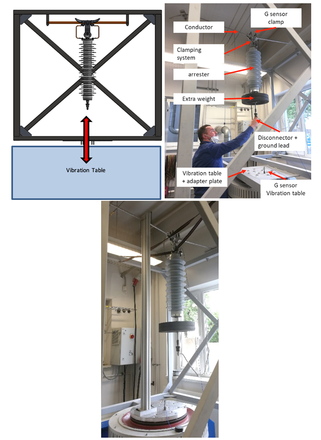
The first test with excitation of the entire frame was difficult to evaluate, since the frame itself absorbed the vibration energy and dampens the vibration. Increasing the stiffness reduced the damping but increased the weight of the frame and reduced maximum test acceleration of the vibration table.
In a second test, the frame was detached from the vibration table and the vibration was applied directly to the conductor section, 20 cm from the NGLA. Even with a short section of conductor, it was still only possible to force the components of the clamping system to vibrate with high acceleration and increased conductor tension. The reason for this is that the weight of the arrester (about 80 kg) kept the clamping system under downward tension and the whole system (arrester and clamping system) formed an inert mechanical unit at this moment.
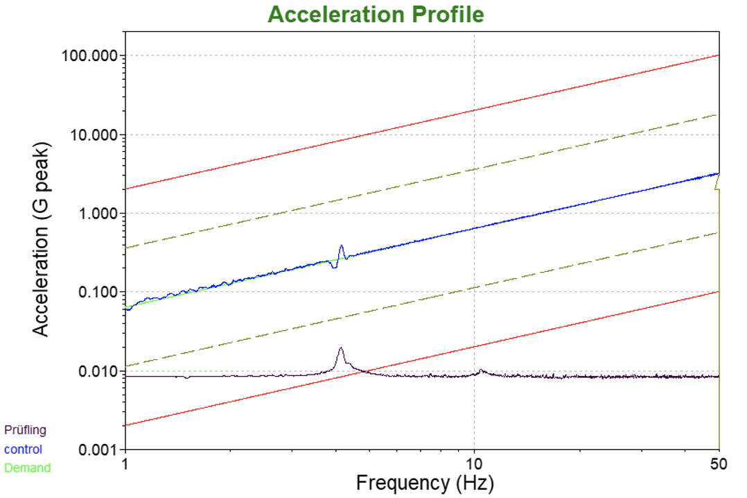
The natural frequency of the components of the clamping system plays a major role as well. Fig. 15, for example, shows a clear acceleration at 3 Hz, when the resonance of the entire system has been reached. This means that the arrester and the clamping system oscillate harmonically up and down with the conductor. At about 11 Hz in this particular case, however, asynchrony arises between the shackle and the ring nut, resulting in an audible rattle and noticeable movement between the two parts. The short-circuit conductor oscillates due to the relative movement between arrester and line clamp.
The extent to which conductor vibration has an influence on the clamping system therefore depends on several conductor-related factors, such as conductor length and weight, vibration amplitude and distance of the NGLA from the insulator. Thus, heavy inertial arresters tend to be less excited by short, light conductor sections than are light arresters with long, heavy conductor sections. This, however, does not necessarily mean that light arresters experience highest severity during the test since in this case less tensile force is applied to the clamping system due to the lower weight. If the effect of the arrester’s inertia on the conductor is neglected, it can be assumed that a heavy arrester will experience the highest load at heavy conductor weight and high oscillation energy if it is suspended at a point with maximum amplitude of line oscillation.
For practical purposes, the following can be derived for any vibration test of the clamping system:
• Testing of one arrester size does not cover other sizes of the same type series;
• In theory,the worst case scenario is an excitation with high amplitude directly on the clamping system, using the heaviest arrester as test object (or an arrester segment with additional weight);
• Due to its weight and inertia, the arrester itself acts as a node in the oscillating conductor. This means that, in reality, only a fraction of the maximum amplitude of the conductor oscillation would occur at the clamping system;
• Each clamping system must be tested, even if the same clamps are used for different conductor bundle configurations;
• This test would be suitable, project-wise, as an acceptance test and not as a type test.

Mechanical Defect of Rigidly Mounted NGLAs Due to Resonant Vibration
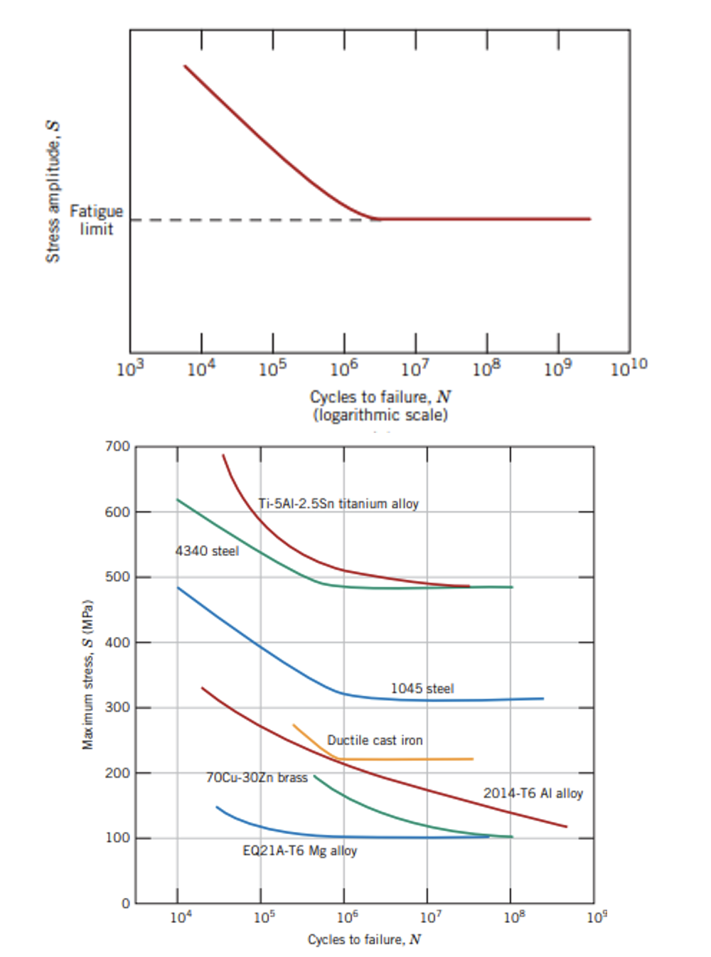
Rigid mounted NGLAs are usually mechanically decoupled from the transmission conductor by a flexible line. This prevents vibration being transmitted from the transmission line conductor to the arrester. However, NGLAs are often used in environments with high wind speeds, thereby exposing rigidly mounted NGLAs to sustained and short duration bending forces. Moreover, wind gusts cause the arrester to oscillate at its natural frequency. In particular, recurring wind gusts can lead to fatigue in materials and mechanical connections due to the repeated mechanical stress. Fig. 17 shows the fatigue limit of different materials at approximately 1 to 10 million cycles.
Since line arresters are usually polymer type, a mechanical effect does not lead directly to visible destruction of the housing but rather to possible loss of internal electrical contact, partial discharge, water accumulation and increased power loss. The fatigue effect is already addressed for repeated bending cycles in the SLL test of IEC 60099-4 and is properly verified with a water immersion test, power loss and partial discharge measurement, etc. Material fatigue could be evident through a cycle-by-cycle increase in deflection; settlement phenomena are evident through sudden increases in deflection within a few cycles, (as can be seen in Fig. 18).
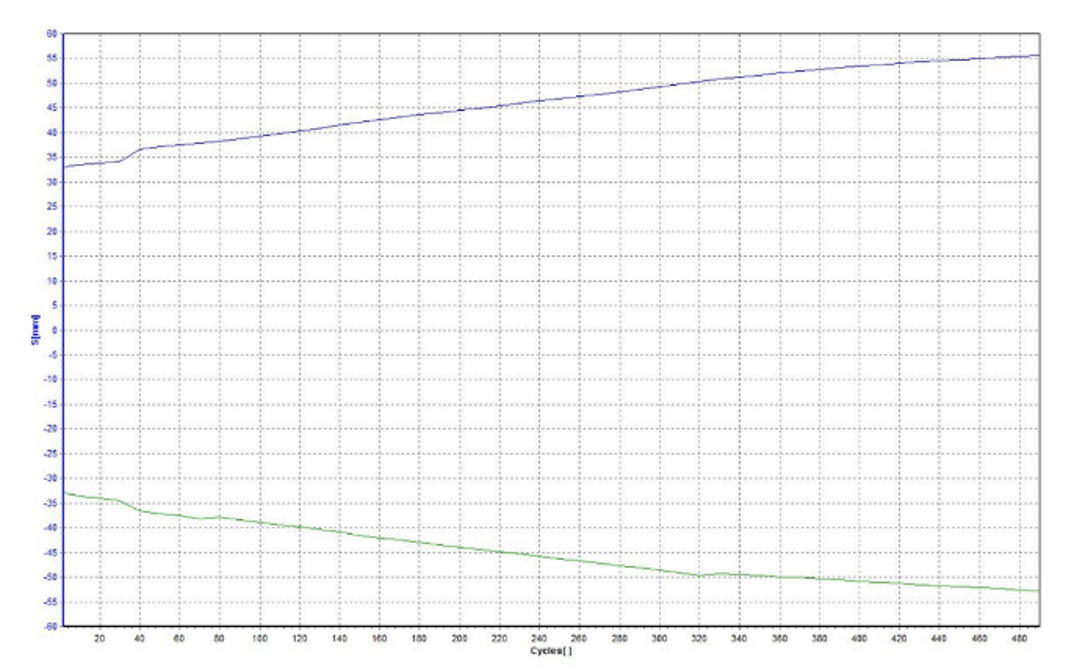
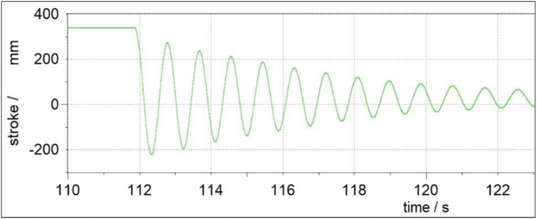
With 1000 cycles, however, the SLL test covers only a fraction of the load cycles acting on a rigidly mounted NGLA during its service life due to wind-induced resonant natural vibration. Assuming 50 wind gusts per hour and a 10% high wind condition, an NGLA will vibrate over 1 million times over 25 years of operation. Depending on the damping characteristics of the arrester, the half-life of a resonant oscillation is between 2 and 10 cycles (as shown in Fig. 19 in this recorded step response of a 360 kV polymer arrester in the snap-back test).
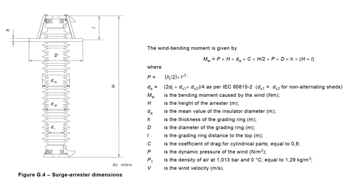
In the worst case, the arrester will oscillate approximately 10 million times due to excitation from wind gusts. Amplitude has previously been a random result by testing with 1 g acceleration at the top of the arrester, which up to now has been explained by seismic accelerations but not by wind gust induced vibration. Amplitude should result from calculation of the wind bending moment, as per IEC 60099-4 Ed. 3.0 Annex G.5 (see Fig. 20).
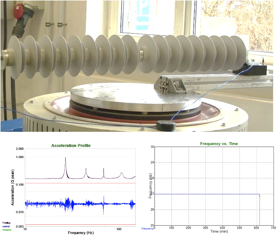
Using this method, a test similar to IEC 60099-8 Ed. 2.0 cl. 8.9.3 can be derived (see Fig. 21):
- Definition of a ‘specified extended long-term load’ as bending moment. (This value should reasonably be smaller than the value of the specified long-term load SLL);
- Vibration test with 10 million cycles and control of vibration according to bending moment, e.g. by means of strain gauges or load cells (most simply done in resonance frequency);
- Final measurement according to IEC 60099-4 Ed.3.0 cl. 10.8.11.3 and 10.8.11.4, similar to Bending Moment Test;
- Calculation of maximum wind load from specified extended long-term load and wind bending moment calculation from Annex G.5., for every size of arrester housing.
Possible pass criteria:
• Drifting deflection to a certain proportion could lead to a failed test;
• Sudden increase in deflection could lead to a failed test;
• Since the vibration is controlled according to bending moment, change in resonance frequency could lead to a failed test;
• Water immersion test including,
· Power loss test
· Partial discharge measurement
· Reference voltage measurement
· No parts broken or lost
Influence of wind gusts on an arrester’s grading-system has not yet been discussed but should be taken into account in standardization and testing in the same way and for the same reasons.
Mechanical Defects on Leads, Hardware & Disconnector
Last but not least, all electrical lines, short-circuit conductors, cable lugs, hot line clamp and disconnector should be critically considered in an NGLA. Statistically, this is where most failures occur often due not to design flaws but due to improper installation. For the mechanically stressed moving components (mostly ring nuts, shackles and U-bolts), good stainless steels are generally to be preferred versus hot-dip galvanized steels since the surfaces suffer from continuous friction between components. Defects in the galvanized layer can lead to corrosion and increased risk of failure with increasing service life.
‘No-Gos’
• Installations where lines or ground leads are under mechanical tension;
• Short line or ground leads that are under mechanical tension when the conductor and insulator are tilted by wind forces, even if the arrester is flexibly mounted on the pole;
• Massive leads or cables – small bending radius;
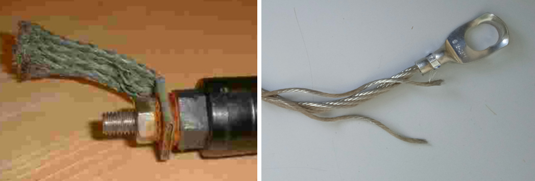
• Weak cable lugs and single/undefined crimping;
• Leads and hardware without corrosion protection;
• Lugs installed perpendicular to the tensile force (if tensile force cannot be avoided).
Basically, the following two failure modes have to be distinguished and tested separately:
1. ground leads with fatigue fracture due to constant vibration and (perpendicular) tension;
2. ground leads that have been released from the lug due to bad crimping.
General Recommendations for Cables, Hardware & Disconnector
• For clamping systems, use proven line clamps, strong yoke plates, shackles and bolts, always with nut plus cotter pin to secure the nut, strong ring nuts, flexible braided tin-plated bypass wires (see Fig 13);
• Bypass mechanical interfaces with suitable leads to ensure proper conductivity;
• Use leads made of round flexible braided strand and tin-plated copper to avoid corrosion;
• For ground lead and bypass wire, 25 mm² will suffice; for line, minimum of 50 mm² cross-section to guarantee corona free operation;
• Solid cable lugs with defined diameter suitable for the target conductor cross-section, e.g. Fig. 22 (left);
• Install cable lugs in such direction that the lead leaves the barrel straight, especially if tensile force is not avoidable;
• Hexagonal crimping tool with defined crimping dimension for the corresponding cable lug and actual conductor cross-section;
• Double crimp for increased release force;
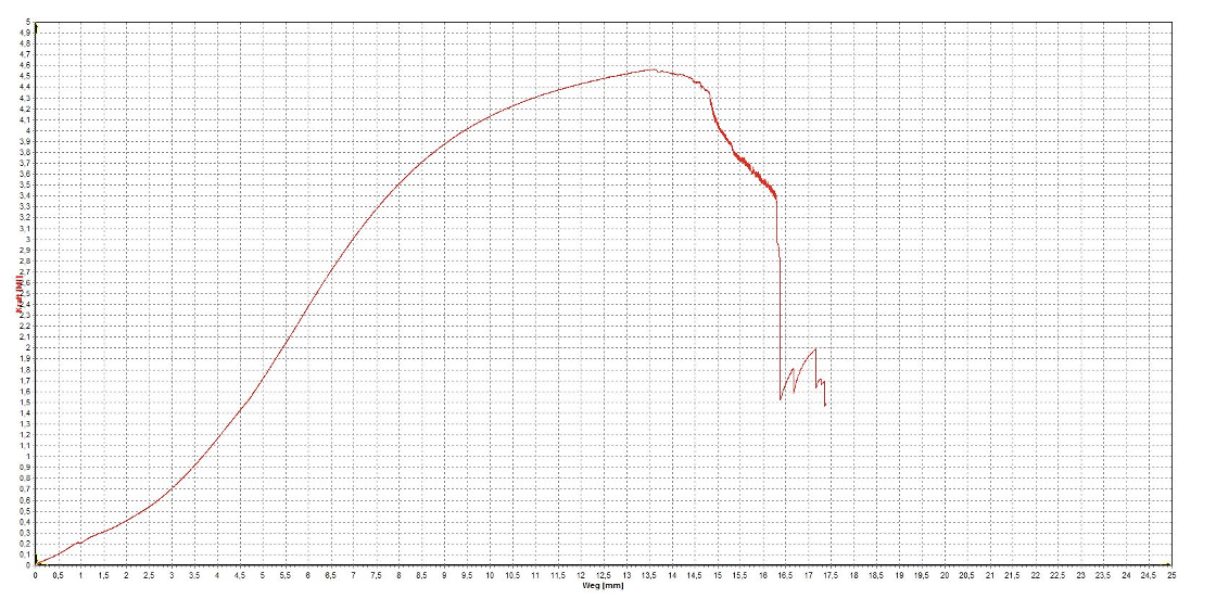
• Random tensile test equal to MBL, SSL and SLL;
· Test for maximum release force (see Figs. 23 and 24). Good reference values are > 2 kN for 25mm² and > 3 kN for 50mm² but at least the specified straight tensile force and perpendicular bending force of the disconnector;
· Test of fatigue limit, for example 1000 sinusoidal cycles with tensile force or multiple shock cycles. Forces should be less then maximum tensile force.
The release force test has been conducted similar to the MBL test, where maximum force is determined by where the sample fails. A safe value, similar to SSL, could be determined by a reduction factor of 20% from the average or smallest release force achieved among a series of tested samples.
General Recommendations for Installation on Tower or Transmission Line Conductor
• Never install line and ground leads under tensile stress;
• Even when the insulator and conductor are deflected by wind force, sagging of the line or ground lead must always be ensured; tension must be prevented as much as possible or the lead should be rein-forced with a chain;
• Insulation clearances to tower or to next cross-arm must be ensured, even when the line or ground lead is sagging;
• For NGLAs with rigid or flexible tower mounting, the disconnector must be positioned on the side or close to the transmission conductor so that no partial discharge emanates from the conductor or that insulation distances would be endangered;
• For NGLAs with conductor mounting, the disconnector must be positioned close to the arrester so that the disconnected ground lead does not assume a high voltage potential, generate a partial dis-charge and possibly endanger insulation clearances by swinging back and forth;
• In the case of flexible tower mounting, the NGLA must not endanger insulation clearances in the event of wind-induced transmission line swing;
• Use armor rods to protect the line against damage from clamping hardware;
• Use vibration dampers at suitable locations, following best practice.

References
[1] Cigré C4, WG 4.39, Effectiveness of line surge arresters for lightning protection of overhead transmission lines, 2021.
[2] K. L. Chrzan, Influence of moisture and partial discharges on the degradation, Euro. Trans. Electr. Power: John Wiley & Sons, Ltd., 2004.
[3] M. Comber, 2022. [Online]. Available: http://www.inmr.com/principal-failure-modes-surge-arresters/.
[4] “NEMA Arresters,” [Online]. Available: https://www.nemaarresters.org/many-uses-transmission-line-arresters/.
[5] W. A. Chisholm, Achieving Long Service Life from Transmission Line Arresters, INMR World Congress Barcelona-Sitges, 2017.
[6] P. L. Products, Aeolian Vibration Basics, Cleveland, 2013.
[7] [Online]. Available: https://studyelectrical.com/2019/07/aeolian-vibration-of-transmission-conductors.html. [Accessed 2022].
[8] Y. Qi, Study on aeolian vibration suppression schemes for large crossing span of ultra-high-voltage eight-bundle conductors, AIME, 2018.
[9] W. Chisholm and D. Harvard, Interaction of Vibration Dampers with Surge Arresters, Berlin: INMR Congress, 2015.
[10] CIGRÉ-B2-TF007, “Interaction of vibration dampers,” 2016.
[11] J. Levine, Experience Applying Surge Protection at Hydro One, Tucson: INMR Congress, 2019.
[12] W. D. Callister and D. G. Rethwisch, Material Science and Engineering, John wiley & Sons Inc., 2014.
[13] IEC60099-4, Surge arresters – Part 4: Metal-oxide surge arresters without gaps for a.c. systems, VDE Verlag GmbH, Ed.3.0:2014.
[14] M. Hughes, Mechanical Testing of Connection Leads for Transmission Line Arresters, Tucson: INMR Congress, 2019.
[15] B. Beske, Line Arrester Installations on the ATC System: What Was Done Right & Further Improvements, Tucson: INMR Congress, 2019.