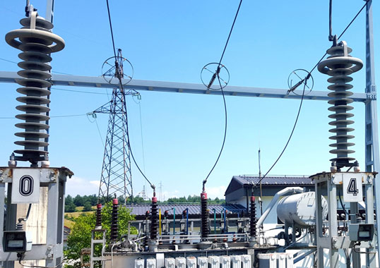
The 1960s to 1970s saw rapid development of the French power system with HV overhead lines and substations located mainly in the countryside. However, as towns expanded, houses, factories, shopping malls and recreation centres were increasingly sited near substations, which were mostly in suburban areas. In fact, some towers were now located in public areas such as gardens and parking lots. A safety concern in such cases was rise in ground potential due to flow to ground of power frequency short-circuit current. This defined what can be called a ‘hot zone’ around a tower.
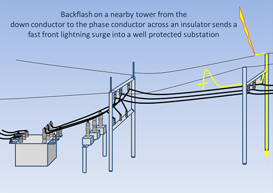
When properly designed, pollution flashover of insulator assemblies and of the gap formed by line conductor and tower are unlikely. But in the event of overvoltage due to lightning, insulator gaps will spark-over and create faults to ground. Traditionally, safety has been improved by lowering grounding impedance of towers as much as possible or by installing shield wires. The latter are efficient in reducing power frequency current flowing to tower grounding systems by paralleling them and offering a return path to the substation. More difficult to control, however, is the way a rise in potential of a HV tower grounding system is transmitted to a nearby grounding system of a low voltage installation that is sensitive to power frequency overvoltage.
This edited past contribution to INMR by Frédéric Maciela of EDF Lab Les Renardières explained how installation of line arresters served not only to protect insulator assemblies from flashover due to lightning but also improved safety as well as quality of electricity on overhead lines.


Selection of EGLA Type Arresters
At the beginning of the 1990s, EDF’s R&D and transmission divisions set up a working group to study the best way to avoid flashover of insulators assemblies on 63 kV and 90 kV lines due to lightning overvoltage. A main objective was to reinforce safety of towers located in ‘hot zones’ while bearing in mind that any proposed solution could also help improve electricity quality. Installing line arresters was deemed the only practical solution since alternatives such as lowering tower footing impedance, increasing withstand of insulators assemblies or installing shield wire if mechanically possible, were all seen as insufficient. For example, a storm cloud is considered to generate tens of kA. Considering that line surge impedances are hundreds of ohms and tower foot HF impedances are tens of ohms, overvoltages that exceed withstand of insulator strings can easily occur.
There are two basic technologies for line arresters: non-gapped (NGLAs) and externally-gapped (EGLAs) – defined in IEC standard 60099-8. NGLAs are similar to substation arresters, both in design and operation. Their main challenge is installation on towers, especially the arrester’s ground connection and associated disconnector.
EDF decided to employ EGLAs with a polymeric housing for the following reasons:
• a more compact design that is lighter and easier to install since there is no need for the disconnector;
• no permanent power frequency voltage and therefore no ageing of blocks nor of the housing;
• no energy stress due to switching impulses;
• less costly than the NGLA alternative.
However, use of EGLAs also creates technical challenges, such as:
1. set-up must guarantee proper operation of the arrester, even in case of wind (e.g. dimensional stability of external gap);
2. insulation coordination must be carefully designed and may need systematic testing in a laboratory on a full sized configuration;
3. verification of operation under polluted conditions is difficult.
Line Arresters Design Considerations
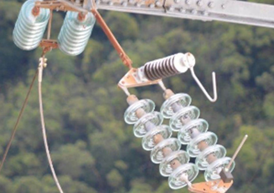
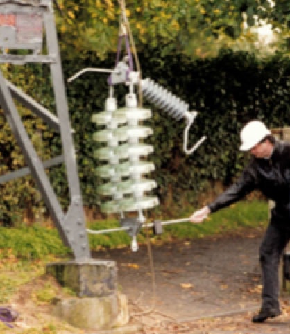
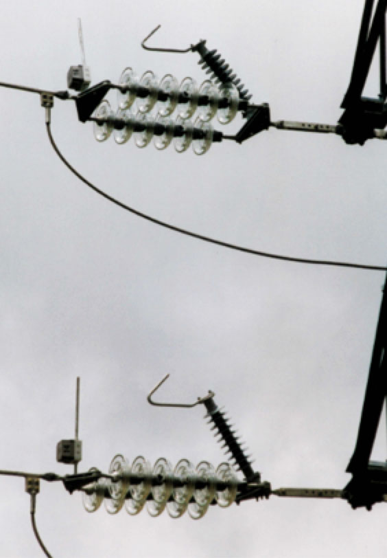
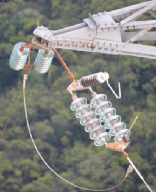
All line arresters at EDF are EGLA type with the series varistor unit (SVU) made up of zinc oxide blocks and polymeric housing – in this case EPDM, which was qualified for the application. The SVU and the external gap are bolted directly onto an insulator assembly with the entire set-up prepared on the ground. This offered benefits, such as:
• installation of the arrester also involved replacement of the insulator string, as common during lines maintenance;
• if displacement of the conductor occurs under high wind, the entire insulator assembly moves as well and length of the arrester gap does not change significantly.
Rated voltage of the SVU is an important parameter since it determines an arrester’s follow current interruption properties when stressed by TOV conditions on the network. The final choice involved a compromise for both applicable voltage levels given that the same arresters have been used on 63 kV and 90 kV lines. Rated voltage selected for the SVU was about 60% of what would be needed for a 63 kV substation arrester and 75% of the value typical for a 90 kV substation arrester. Such a decrease in rated voltage is possible in the case of an EGLA since the power frequency follow current is limited to a few amps and occurs only within the half-period during which the impulse creating spark-over of the gap is applied.
Energy design of line arresters must also take into account factors such as: lightning activity, tower foot impedance, rated voltage of the SVU, presence or absence of shield wire and acceptable arrester failure rate. This is therefore a statistical approach. In the case of EDF’s application on 63 and 90 kV lines, it was considered that energy design of the line arresters should be at least 200 kJ so as to guarantee an average annual failure rate lower than 1 per 1000. Calculation was based on EMTP models and lightning data collected by CIGRE.

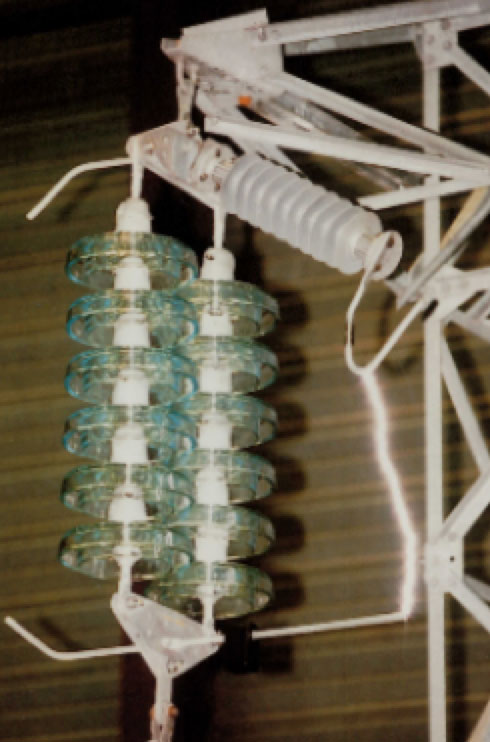
Arrester failure mode has to be completely safe since these were being installed in public areas. Choice of a polymeric housing helped achieve satisfactory results in this regard, with short-circuit tests conducted on the complete set-up, including arrester and insulator assembly. The sample was deemed to have passed if:
• no hard pieces of the arrester or of glass fell to the ground;
• the insulator assembly maintained its mechanical integrity;
• the arrester quickly self-extinguished flames; and
• the associated fault indicator was visible before end of the test.
Presence of a fault indicator was regarded as necessary so that line inspection could locate with certainty any failed arresters.
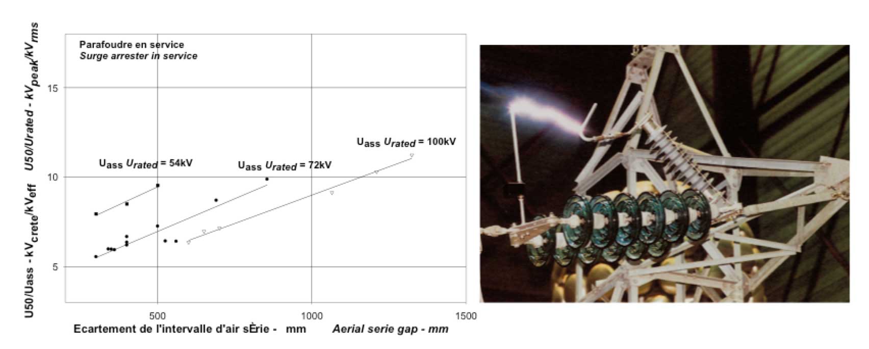
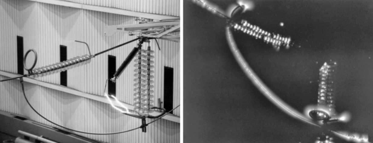
Finally, insulation coordination is key to proper operation of an arrester. When the SVU is considered to have failed, i.e. to be equivalent to a short circuit, the gap shall withstand switching impulses. When the SVU is healthy, its gap shall spark over before all others gaps surrounding the arrester (i.e. mainly the insulator gap and the distance between line conductor and tower, even in case of displacement due to wind). It was decided to perform these tests under the most representative configurations of the actual application. For this purpose, a full-sized 90 kV tower head was set-up in the laboratory. Calculation of the U50 of the gap can be unpredictable because of complex geometry. This leads to atypical values of gap factor, due also to presence of the SVU that acts as a capacitive divider when an impulse is applied. The conclusion of these tests was that it is important to check that the arrester gap is the first gap to spark-over when the EGLA is installed on a tower, regardless of absolute spark-over voltage of the arrester alone.
EGLA Design for 225 kV & 400 kV: Additional Challenges
When the possibility of also using the 63/90 kV EGLA concept on 225 kV and 400 kV lines was studied, two points emerged:
1. insulation coordination; and
2. compatibility of the presence of EGLAs with live working procedures.
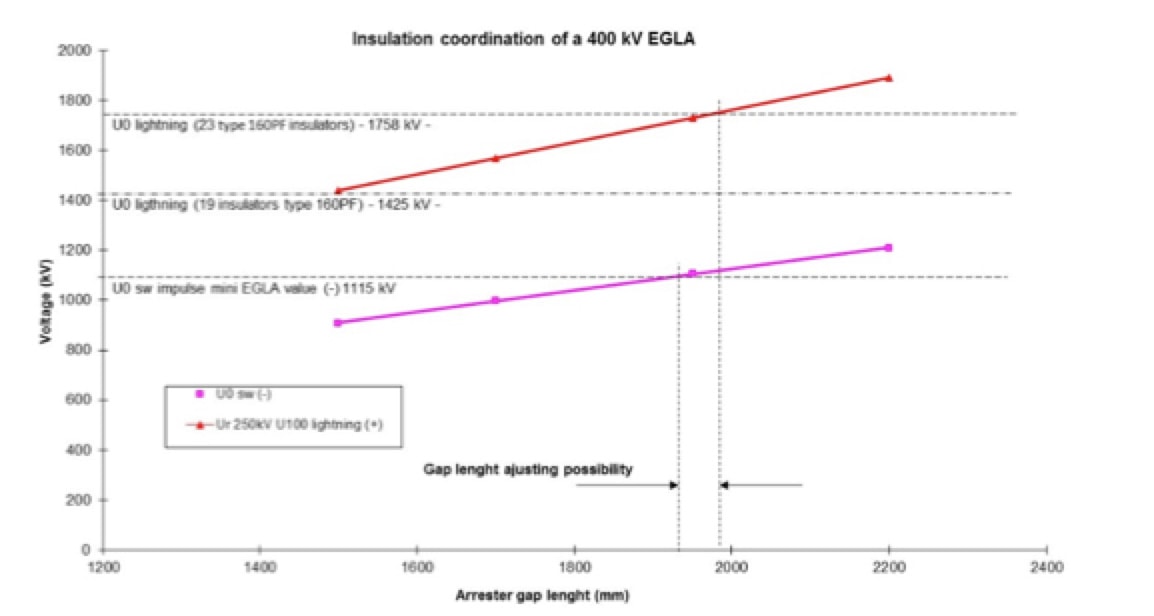
When EDF studied the possibility of also using the 63/90 kV EGLA concept on 225 kV and 400 kV lines, two points emerged: insulation coordination and compatibility of the presence of EGLAs with live working procedures. Insulation coordination was the more challenging because of the relatively high voltage amplitude of switching impulses. One solution was to increase the number of insulators on protected strings since this would allow more margin in electrical dimensioning (withstand of switching impulses and spark-over for lightning impulses). Adding one or two additional insulator discs increases string length and particular attention must therefore be paid to height of line conductor with respect to the ground as well as to clearance of line conductors in tower windows. An alternative approach was to decrease switching impulse voltage, thereby avoiding some charges being stocked on conductors, e.g. by using instrument voltage transformers.
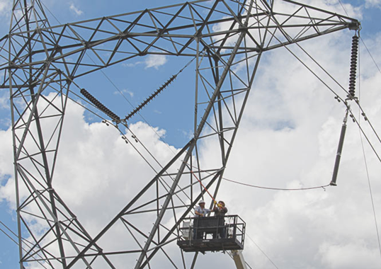
The other challenge concerned live line work, critical to operation of many 225 kV and 400 kV lines. Presence of an EGLA introduces into the work zone a gap for which length must be compatible with live working distances and this creates another parameter when selecting EGLA gap length. At EDF, design of line arresters permits live installation of 225 kV EGLAs due to fixing the SVU with a pivot that allows an increased gap during live installation. Once the insulator and EGLA assembly has been installed, the operator can move the SVU to its normal operating position using a live line tool.

Optimizing Line Arresters: Number & Location
When planning installation of line arresters, the first task is to determine the main purpose, e.g. mitigating ground potential rise in hot zones, improving electricity quality or possibly both. The line itself must then be characterized in terms of geometry (i.e. number of circuits, arrangement of phase conductors, presence or absence of shield wire), length, tower foot impedances, topography, local lightning activity). If the main goal is to mitigate rise in potential, the conservative approach is to equip every insulator string on a tower with arresters to avoid any spark-over due to lightning on the structure. If the line is equipped with shield wire, it may also be necessary to install arresters on nearby towers to avoid some ground faults occurring too close to the protected tower as well as to benefit from a distribution of the power frequency fault current in multiple grounding systems.
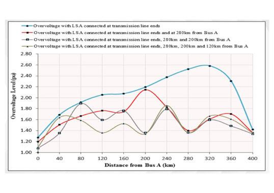
By contrast, if the main goal is to improve electricity quality, the objective has to be expressed using a statistical approach. If no outages are allowed, every insulator string must be protected with line arresters. But this is costly and optimization can therefore be considered by utilizing specialized software such as EMTP. For example, a study was conducted for a 17 km line located on the Caribbean island of La Guadeloupe.
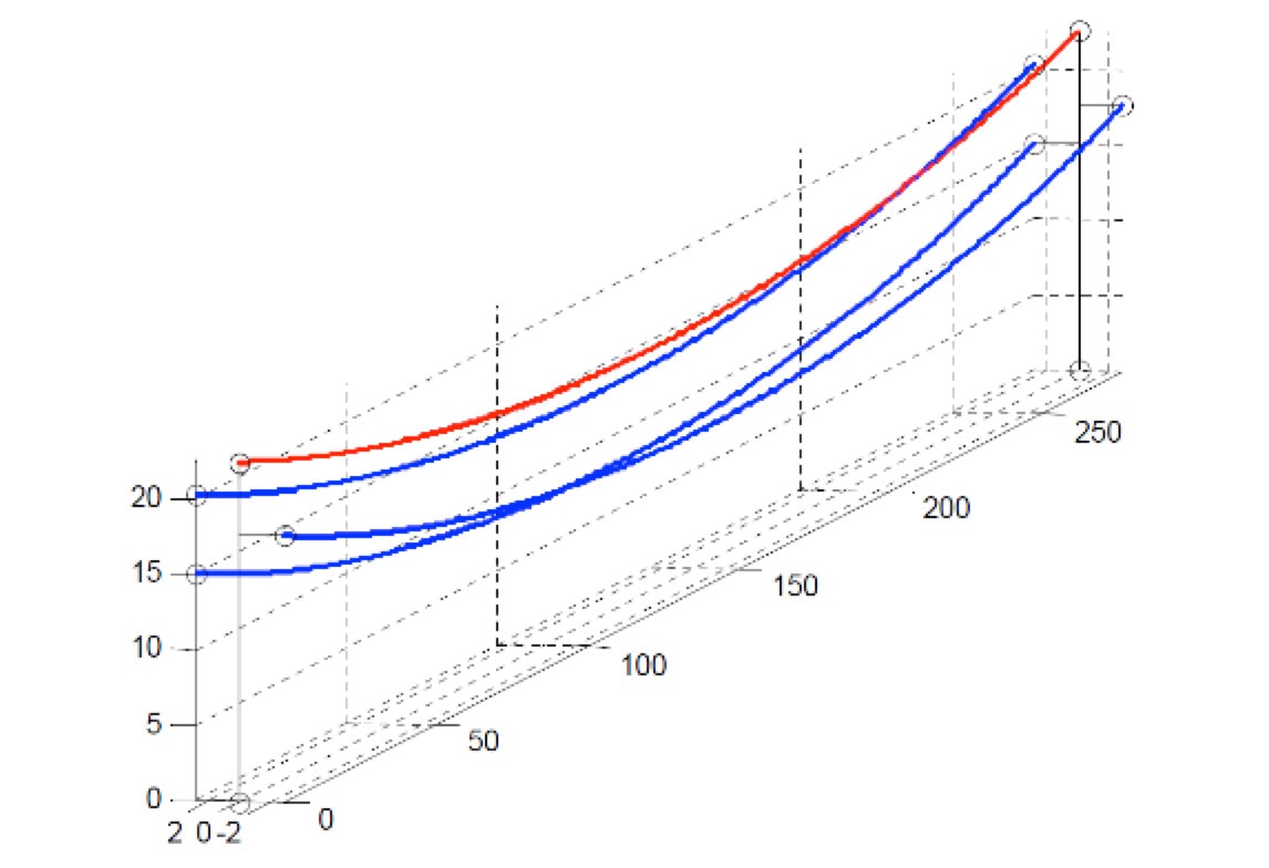
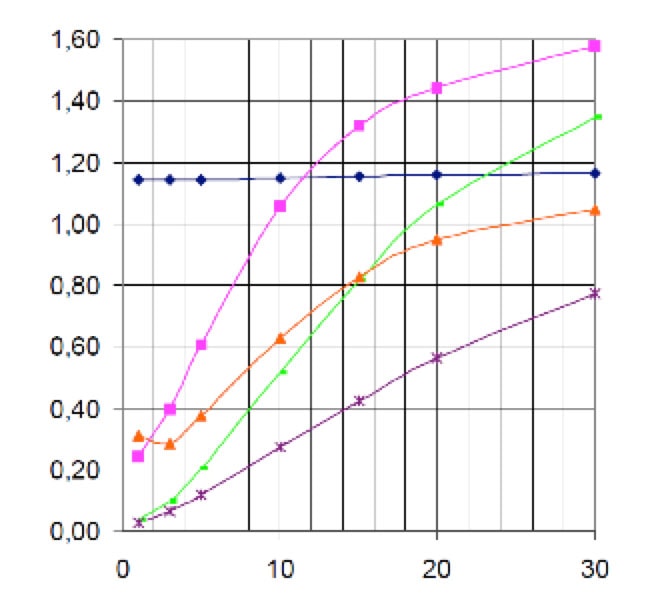
(blue) no shield wire, no arresters;
(pink) with shield wire, no arresters;
(green) with shield wire, arresters on conductor C;
(orange) without shield wire, arresters on the upper conductor A;
(purple) no shield wire, arresters on middle and upper conductors.
Field experience for this line (no shield wire, no arresters) showed an outage rate of about 1.33 to 1.5 per year. Calculated value was 1.15, independent of value of tower footing resistance, which showed that the computation model was accurate. The main conclusions were:
1. without shield wire, ground connection resistance has no influence;
2. with shield wire, very low tower footing resistance dramatically decreases outage rate;
3. with line arresters, good results can also be achieved. But installation must be carefully chosen considering ground resistance and presence or absence of shield wire.
Another important point to take into account is line topography. For example, on some islands storms always arrive from the same direction and are blocked by mountains extending over part of the island. Line arresters should ideally be installed in this area. Considerations such as this can lead to optimization in number of line arresters to be installed by achieving a given target for power outages while also reducing costs.

Efficiency of Line Arresters: Past Investigations
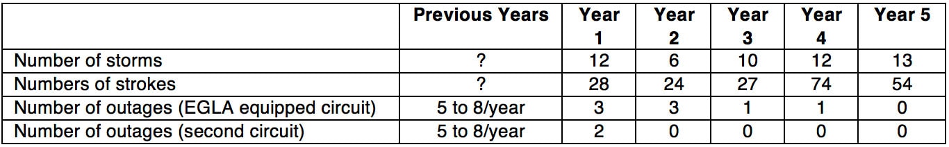
To validate computational models, an investigation was conducted on a 10 km long 90 kV double circuit line located in central France. This line is equipped with shield wire and tower footing resistance values average 200 ohms due to poor soil conductivity in the area. Over the 16-year period studied, the line’s outage rate due to storms was between 5 and 8 per year – judged as unacceptably high. 60 EGLAs were installed on every tower of one circuit but only on the bottom two phase conductors. The fault indicator of each arrester was replaced by a monitoring box supplied by solar cells, capable of dating and recording maximum current value whenever an arrester gap sparked. Data was stored and could be downloaded from ground level by basic radio modem. The investigation covered the next several years. During this period, the French Lightning Location System indicated that 207 lightning strokes to ground occurred near that line. Peak values of lightning currents recorded through the arresters were between 9 kA and 35 kA. The conclusion was that line arresters were effective in reducing outage rate and optimizing their number and location was possible to achieve any desired goal. For example, in the case of double circuit lines, arresters could be optimally installed on only one circuit. This reduces but does not eliminate outages on that circuit, which essentially becomes the ‘weak circuit’ but still cancels outages on the other circuit.
Field Experience: Reliability of Line Arresters & Energy Design
The main stress on EGLAs is provided by lightning currents. Energy design is a key point yet evaluation of the energy associated with lightning strokes is difficult since this depends not only on line characteristics but also on topography and storm activity in the area.
Former IEC energy Class 1 was used for the 63/90 kV EGLAs at EDF and Class 2 for the 225 kV and 400 kV EGLAs. After some 18 years of operation of thousands of EGLAs installed across France, failure rate (e.g. due to energy overstress) was extremely low, i.e. less than 1/1000/year. In the case of French overseas territories, such as its Caribbean islands, failure rate has been higher. For example, in La Martinique, all 20 EGLAs installed in one part of a 90 kV overhead line had to be replaced after 15 years of service. This field experience demonstrated that energy class of line arresters must be carefully chosen. Yet this parameter can be unpredictable and only field experience can provide the basic data needed for future designs and projects.
Conclusions
Based on an intensive program of laboratory tests as well as computational studies and given almost 20 years of experience involving thousands of samples, installation of line arresters has proven highly effective in mitigating ground potential rise of towers and improving electricity quality. Optimization in number and location of arresters is possible to achieve any specific goal. Some EMTP models are sufficiently accurate to estimate outage rates of overhead lines equipped with arresters. Selection of the EGLA concept represents a technical-economic compromise and requires a rigorous specification and qualification procedure based on laboratory tests with full-scale configurations.