[inline_ad_block]
When it comes to DC line applications, there are ‘pure’ DC connections and also ‘hybrid’ connections – the latter being a solution to replace an AC system on an existing line route with a DC bi-pole to increase transmission capacity. While it is now well accepted that application of composite insulators is state-of-the-art for AC systems, documented field experience for pure DC lines is still limited. In 1995, CIGRE WG 22.03 published results of a survey on experience with HVDC lines in the U.S. and New Zealand. These were early generation composite insulators with silicone rubber (SR) and EPDM housings yet service experience was mostly good. Moreover, certain advantages were confirmed in areas with vandalism or pollution problems. It was also noted that, under similar service conditions, EPDM showed a greater tendency to experience flashovers compared with equivalent SR. Other application cases have also offered insight. For example, after circa 25 years’ service, insulators with HTV silicone rubber housings were removed from 500 kV HVDC lines in the U.S. and South Africa and carefully analysed. Both lines have had good service histories and the SR insulation has performed excellently across pollution classes ranging from light to medium to partially high. Laboratory tests on these insulators confirmed that both hydrophobicity and hydrophobicity transfer property (HTM) of their housings were maintained.
In the case of hybrid lines where DC and AC systems co-exist on a single structure, there are still no large-scale systems yet in service. However, some useful data has been collected on a short test line and also from full-scale laboratory testing. It is expected that such hybrid lines will require a compromise in terms of insulator length, especially when an existing AC tower is being used. This will then have an impact on the specification and description of insulator material properties and hence design – especially creepage distance for a given voltage class and service environment.
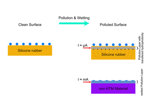
Positive service experience has always been linked to stable hydrophobic behaviour. At the same time, due to the dynamic nature of this property, it is now also well established that one must distinguish between hydrophobicity retention, recovery and transfer – and only SR offers all these performance-enhancing processes in service. Keeping in mind that a DC field can cause more pollution accumulation under the same conditions, the presence of all three dynamic processes is decisive to achieve an overall hydrophobic insulator that will suppress leakage current and prevent flashovers without need for maintenance. Suppressed leakage current also reduces risk of anodic corrosion on end fittings that can affect an insulator’s sealing system, depending on design.
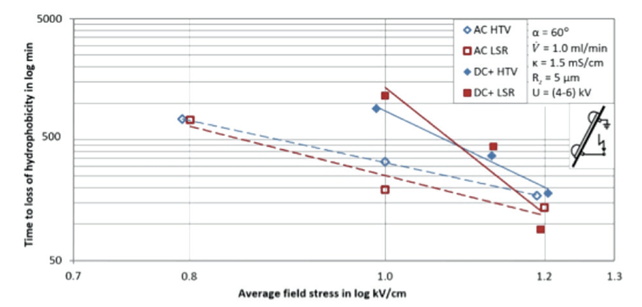
Research has used the Dynamic Drop Test (based on the Inclined Plane Test philosophy) to demonstrate that loss of hydrophobicity is faster with AC stress when the corresponding DC stress is related to the rms-value of the AC voltage (see Fig. 1). This example shows behaviour of an HTV and an LSR silicone – both commercially available for outdoor HV insulators but with the HTV enriched with aluminium trihydrate to enhance resistance to tracking and erosion. Voltage stress is shown as average field stress (applied voltage divided by creepage distance). The DC+ curve is above the AC curve however is steeper and this explains successful service experience with hydrophobic housing materials. Moreover, higher creepage distance is typically used for DC applications than for AC in similar environments with equivalent pollution levels.
CLICK TO ENLARGE

CLICK TO ENLARGE
Another design aspect has to be mentioned as well. Risk of pollution flashover depends on many factors, e.g. conductivity of pollution, effectiveness of electrolyte conductivity (possible encapsulation by hydrophobic low molecular weight SR chains), voltage stress, installation position, hydrophobicity, pollution distribution, efficiency of creepage profile and average diameter. In a ‘classical’ pollution flashover of a hydrophilic surface, there is a relationship between flashover voltage and average diameter: Uflashover ~ daverage-0.38. Impact of average diameter is corrected in IEC 60815-3 as shown in Fig. 2, given HTM characteristics.
CLICK TO ENLARGE
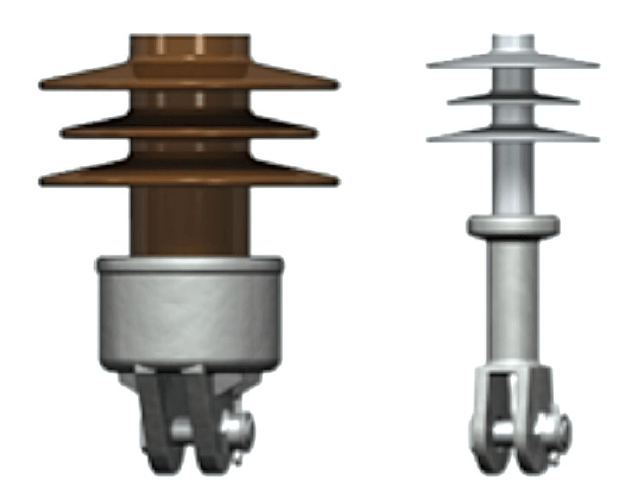
Such correction starts at 300 mm (still in discussion for DC and might be 250 mm) for increasing average diameter. The zone below 300 mm is of special interest when comparing the difference between conventional and composite insulator technology in terms of average diameter. A porcelain long rod and an equivalent composite long rod, both rated 120 kN, have significantly different appearance (Fig. 3). This example results in differences in average diameters of 111 mm to 48 mm. Assuming a fully hydrophilic composite insulator, the relationship: Daverage/porcelain/Daverage/composite = (111 mm/48 mm)-0.38 = 0.73 shows that under the same pollution conditions the slimmer composite insulator outperforms the porcelain insulator by factor of about 1.4.
This can result in application of less creepage meaning shorter insulators. A similar consideration is possible for cap & pin insulators that have even larger diameters. It’s worth mentioning that, when applying the same model of average diameter and fully hydrophilic effect, conventional insulators with a hydrophobic coating would behave much like such insulators without coatings. The goal: the slimmest possible insulator with permanent hydrophobicity due to long retention and fast recovery or transfer would be preferred for DC (and also for AC).
Dr. Frank Schmuck

