The ongoing expansion of wind power is placing growing demands on the dynamic capacity of transmission systems. Utilities are therefore looking closely at how existing lines can be utilized more efficiently.
One attractive means of enhancing an existing line’s power transfer capacity is to convert it from AC to DC. For example, a feasibility study at a past Cigré Session demonstrated that the thermal power transfer capacity of 300 kV lines in Norway could increase from 70 to 80% by conversion to DC. Accounting for the fact that many AC lines cannot operate at their thermal limits because of stability constraints, this relative capacity increase might prove even greater.
The key issues for AC to DC conversion of transmission lines are corona and electric field effects, which together determine the maximum DC voltage level that can be attained. However, insulation aspects are also critical since they will affect power transfer capacity as well as a line’s operational reliability.
This edited past contribution to INMR by Jan Lundquist and Igor Gutman in Sweden and K. Halsan of Statnett in Norway, reviewed these aspects.

Insulation aspects associated with AC to DC conversion comprise such factors as:
• Line insulators;
• Lightning performance; and
• Safety clearances.
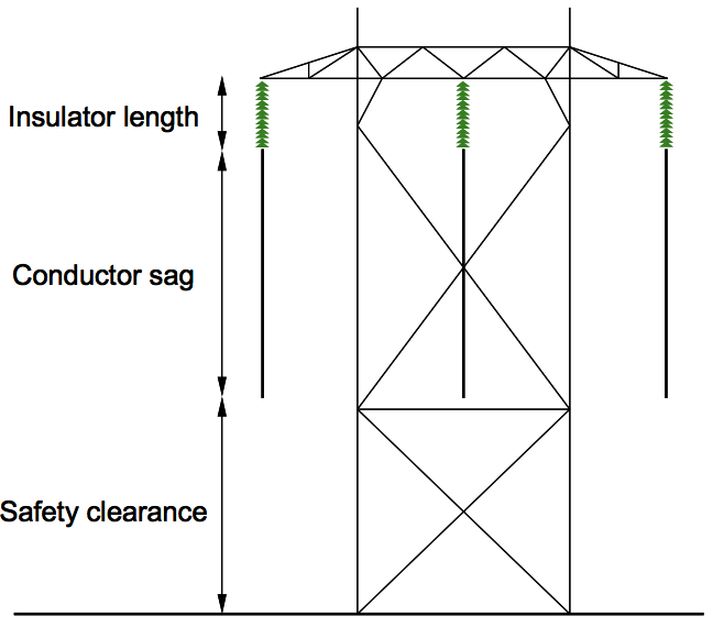
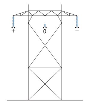
When converting a line, it is essential to utilize the vertical distance between cross-arm and ground as efficiently as possible without jeopardizing reliability or safety. This vertical distance is made up of three components: insulator length, conductor sag, and safety clearance to ground (see Fig. 1). All three are therefore closely related to the line’s power transfer capacity.

Insulator length is related to line voltage while conductor sag to its current rating. Larger conductor sag permits higher conductor temperature and higher current rating. The safety clearance to ground is determined by local safety codes and in some cases international standards. Required clearance is either directly related to voltage level or indirectly by being dependent on insulator length.
It is obvious that longer insulators allow for a higher voltage level but provide less room for conductor sag, thus reducing current rating. To maximize the power capacity of a converted line, it is therefore essential to find the optimal balance between voltage and current rating. From an economic point of view, the best combination may well be to choose a higher voltage and accept a lower current rating so as to minimize power losses.
Required length of insulators is an important parameter in this optimization process. If shorter insulators can be used for the same voltage level, this will permit larger conductor sag while retaining the safety clearance to ground. Furthermore, if the required safety clearance is proportional to insulator length, shorter insulators will provide even more room for conductor sag.
Insulators for Converted Lines
Cap & pin insulators for AC cannot be utilized for DC due to issues of corrosion. While porcelain long rod insulators are less problematic in this regard, the most common choices for DC lines in recent years are either glass or composite insulators.
The relative pollution performance of glass and composite line insulators for DC was obtained using the solid layer method, with no recovery of hydrophobicity following pre-conditioning allowed in the case of the composite insulator. The findings were then applied to the different pollution conditions affecting Norway using a statistical dimensioning approach, i.e.:
• Pollution performance expressed in terms of the 50% flashover voltage per unit length of insulator as a function of pollution (SDD) level in the test.
• Insulator pollution performance then combined with a statistical description of different pollution severities in terms of ESDD 2% levels.

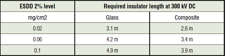
The required insulator lengths were then determined by means of a statistical dimensioning methodology developed at STRI and having the following assumptions:
• ESDD 2% levels were chosen as 0.02 mg/cm2, 0.06 mg/cm2 and 0.10 mg/cm2, representing low, average and high levels within the medium pollution severity range defined in the revised version of IEC 60815-1.
• Acceptable pollution flashover rate was chosen as 0.1 per year for a 100 km line assuming 10 pollution events per year.
The results of the calculations are summarized in Table I in terms of required insulator length for a DC voltage of 300 kV.
To illustrate the impact of pollution level and insulator length on power transfer capacity, it was assumed that a 300 kV AC, twin Grackle conductor line would be converted to bipolar ±300 kV DC to comply with corona and field effect limits. The converted line (shown in Fig. 2 employs the centre phase as a metallic return when one pole is out of operation.
For the three pollution levels, the required lengths of glass and composite insulators were calculated based on test results. In this case, the safety clearance to ground was assumed at a constant of 8m, independent of insulator length. The resulting maximum allowable conductor sag was determined for a typical span length of 330m. The corresponding maximum conductor temperature was used to calculate the maximum DC current rating for an ambient temperature of +20°C. Finally, maximum DC power transfer capacity at +20°C was determined for a DC voltage level of ±300 kV.
From Table 2, it is clear that composite insulators provide more space for conductor sag and considerably higher maximum DC power transfer capacity compared with glass.
Lightning Performance of Converted Lines
Operational reliability during conversion from AC to DC will be affected not only by insulator pollution performance but also in terms of the converted line’s lightning performance. (Switching overvoltages, on the other hand, will not be a concern after conversion to DC).
The primary impact on lightning failure rate will come from the change in insulator length, which then influences the risk of back flashovers across the insulators. Other influences on lightning performance are caused by the changeover from AC to DC. For example, most lightning strokes to shield wires or tower tops cause a negative voltage on the tower (since the majority of strokes are of negative polarity). This means that the highest overvoltages tend to occur across insulators on the positive DC pole, i.e. the constantly applied DC voltage will cause a statistically higher overvoltage across these insulators than under AC.

Another effect is caused by negative lightning strokes to the pole conductors, which in a similar way cause statistically higher overvoltages across the insulators on the negative DC pole. As a result, back flashover rate on the positive pole and shielding failure rate on the negative pole will increase slightly after conversion (assuming the same insulator length is used).
However, as already shown, DC insulator length must be selected with regard to pollution conditions. The effect of insulator length on lightning failure rate of a line both before and after conversion was calculated by means of the line performance estimator (LPE) program, which handles both AC lines as well as converted DC lines.
Using a ground flash density of 0.5 per km2, an average tower footing resistance of 100W, a soil resistivity of 1000Wm, and allowing for soil ionization, the lightning failure rate of the line was calculated for the existing AC line as well as for the converted line equipped with DC composite insulators. The results are shown in Fig. 3 for the range of different insulator lengths as required under different pollution scenarios.
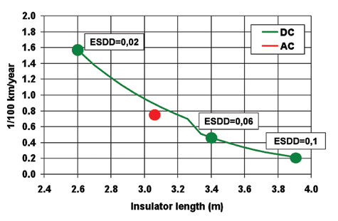
It can be seen from Fig. 3 that lightning performance of the converted line under more severe pollution is actually much better than for the original AC line. As a result, there is the possibility to reduce insulator length without leading to unacceptable lightning performance. However, this would then require more efficient DC composite insulators in terms of pollution performance per unit length.

Conclusions
Composite insulators make conversion from AC to DC more attractive since they allow the vertical distance between cross-arm and ground on an existing line to be better utilized. However, at higher pollution levels, the insulators may have to be longer than actually needed from a purely lightning performance point of view. Conversion of AC transmission lines to DC would therefore benefit from DC composite insulators designed to have especially high insulation efficiency under polluted conditions.
[inline_ad_block]