Reliable operation of transmission and distribution systems depends on correct selection of insulators. But proper dimensioning can be a challenge since it requires knowing both site contamination and insulator withstand to specific types of contaminants. Moreover, contamination level depends on a number of site-specific parameters. For example, wind, rain, humidity and the physico-chemical characteristics of pollutants all play a role while secondary parameters such as wind direction and rain intensity also have an influence. A priori characterization of any site is further complicated given the uncertainty when estimating each relevant parameter. Specific statistical methods are then necessary to reduce uncertainty and allow for more robust estimation. Contamination measurements represent another approach to classify a site and can be performed directly on energized or de-energized insulators or using specific dust collectors (e.g. DDDGs). Both priori characterization of a site based on meteorological parameters and measurements using dust collection devices require a further step, namely evaluating the actual contamination deposited on insulator surfaces. All techniques then need feedback from past operating experience that can help further refine knowledge of the contamination level of a site.
Withstand to specific contamination is related to specific insulator characteristics and many tests have been performed over the years at different laboratories involving different insulator types and profiles. Such data have been assembled to obtain mostly 2-parameter models that provide the unified specific creepage distance (USCD) for any given specific contamination level. The final goal when selecting the proper insulator for a specific site is evaluating risk of failure in order to ascertain whether or not this value is lower or equal to acceptable risk. Acceptable risk usually varies with voltage level and type of installation (e.g. line or substation). Confidence in final selection comes from past field experience.
This edited past contribution to INMR by insulation specialist, Massimo Marzinotto, of Italian TSO, Terna, performed such analyses separately for line and station insulators since acceptable risk is generally different for the two.

Insulator Dimensioning & Risk
Dimensioning insulation can be performed through statistical methods or in a deterministic manner. The former allows estimating risk of failure while the latter is based on experience using safety factors (but where risk of failure remains unknown). Evaluation of risk of failure is performed through the following equation, which yields probability of flashover for an adverse contamination event:
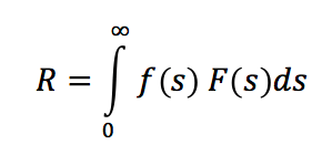
where f(s) is probability density of the contamination (s) on the insulator surface depending on site characteristics as well as on insulator parameters (i.e. profile, diameter, inclination, etc.). F(s) is cumulative flashover probability function of the insulator/string for any contamination (s) given applied voltage and insulator characteristics (i.e. profile, diameter, creepage factor, type of contamination (whether A or B), hydrophobicity class, number of insulators in parallel, altitude and, in the case of Type A contamination only, coefficient of uniformity ratio (CUR) and NSDD level. From risk of failure, it becomes possible to define number of expected flashover events each year, Ne:
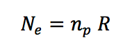 where np is yearly presumed number of unfavorable events (i.e. that can lead to flashover). Ne is compared with number of allowable flashover events each year (Na) and thus considers insulator dimensioning acceptable if Ne ≤ Na. As mentioned, F(s) can be estimated based on laboratory tests while f(s) can be assessed either from a measurement campaign or simulated using specific models. np is strongly related to number of days per year that can give rise to 1) wetting of the insulator and 2) conditions able to lead to flashover. This number has been evaluated at somewhere between 20 – 40 days per year but is general and needs to be refined on a case-by-case basis. Na depends on voltage level, line or substation and on specific decisions by the transmission system operator. Considering that flashovers due to insulator contamination can sometimes cause permanent outages, a possible value could be somewhere between 2 and 5 times lower than allowable number of back-flashover events from lightning striking a line or station.

For example, for a line having an annual back-flashover rate of 0.1/100 km (i.e. 1 event every 10 years/100 km of line), Na should be 0.02 to 0.05/100 km (i.e. 1 event every 20 – 50 years/100 km of line). On the other hand, for a station where allowable yearly flashover from lightning events is on the order of 0.01 (i.e. 1 event every 100 years), Na could be 0.002 to 0.005 (i.e. 1 event every 200 to 500 years). Based on this case, it can be concluded that yearly allowable events, Na, for a substation is an order of magnitude lower than for a 100 km line. It is important to note that parameters can be time dependent, in particular np, but also other parameters that contribute to estimating f(s). Updating parameters can be based on feedback from the field. For instance, if a new steel mill is built in the service area, np can change and f(s) would shift to the right. Usually contamination maps are used even if they cannot give sufficient information for assessment of risk, R. In fact, these are contour maps that report maximum value (or sometimes mean value) of contamination for each level only, but give no information on statistical distribution and standard deviation. Re-mapping is usually performed after a number of years in order to evaluate possible variations in site contamination level. Such activities are costly and are usually undertaken only if the returns from the operation highlight the need.
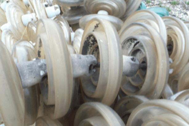
This activity has recently begun in Italy with 200 measurement sites uniformly distributed across the country. Such measurements involve sampling every 3 months over a period of two years, i.e. a total of 8 samplings uniformly distributed over the year (March, June, September and December). In order to simplify sampling, non-energized strings of 10 standard profile cap & pin glass insulators have been installed on selected towers at a height just lower than the lowest conductor. For each sampling, one insulator is selected as reference and the swab technique employed is in line with what is used for measuring ESDD and NSDD. The uppermost and lowest insulators in the string are not used in such measurement in order to avoid ‘end effects’. In order to give greater effectiveness to data collected, these will be matched with units returned from operation in the field. This will help not only re-define color (contour level) of the map but also understand the efficiency of measurements.
Furthermore, if theoretical models of contamination can be refined or improved this can also help better estimate risk of failure, R, and expected number of flashover events yearly, Ne. To monitor specific sites over the country that are known as heavy contamination areas, Terna (formerly ENEL) decided 20 years ago to adopt a monitoring system that is able to survey the severity of contamination deposited on insulators and give warnings whenever this exceeds specific thresholds. This monitoring system is called AMICO 2 (an evolution of the first) with severity of the contamination deposit evaluated through surface conductance of a post insulator exposed to natural contamination. The surface conductance measurement is performed without altering the natural conditions and applying a voltage equal to 12.5 kV (rms) for only 4-cycles. The measurement is performed periodically taking into account the value of other recorded meteorological parameters: wind direction and velocity, temperature and humidity. The system is thus able to convert the surface conductivity in contamination level giving in this way warnings and also alarms when specific thresholds are exceeded. Contamination empirical models based on meteorological variables is another field in which the scientific community is deepening the knowledge in order to get robust models for the contamination prediction on insulators surfaces. These models can only be validated from field returns. More recently another interesting field of investigation has been the resilience of power systems as well as resilience of overhead lines and substations against contamination. This means that insulators must be able to withstand even extreme contamination conditions. Consequently, number of expected flashover events yearly, Ne, must be lower than normal, imposing a more stringent approach to insulator/string dimensioning.
Finally, the insulator has to guarantee safety of the public, of maintenance crews as well as other power system equipment and infrastructure located beneath a line or near a station. Reliability of insulators in this regard is difficult to quantify. Obviously the risk of a mechanical failure always give rise to condition that can have an impact on the safety of people, animal and things and consequently the risks shall be much lower than the one accepted for a flashover event due to contamination. The risk evaluation in this sense is difficult to be achieved for the complication in the inference of the statistical distribution of all the stresses that can have an influence on a mechanical failure of the insulator. For this reason a pure deterministic approach to the problem is adopted taking adequate margins between the maximum stress that an insulator can face during its service conditions and its mechanical withstand value. Such margins shall be enough to guarantee a very low risk of mechanical failure.
Another relevant aspect is ageing since it affects insulator performances. Insulator ageing is a combined action of electrical, mechanical and environmental stresses. The higher is the synergy among such stresses, the larger is the ageing rate. The synergy among these stresses is higher for composite insulators, while it is quite weak for ceramic and glass. This is confirmed from the experience of many years of operation at different voltage levels and different environment conditions. In this respect, TERNA decided, immediately after the first installations of composite and RTV insulators, to set up specific test protocols to be applied to insulators taken from the field after a number of years of operation. Such test protocols aim to 1) point out changes in the ageing process, if any, and 2) get information to diagnose the insulator end-of-life. The final design of an insulator is thus refined from field returns. Such fine-tuning in the insulator dimensioning represents the necessary information for a proper confidence in the insulator dimensioning evaluation.
Overhead Line Insulators
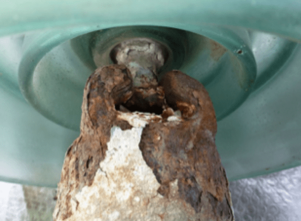
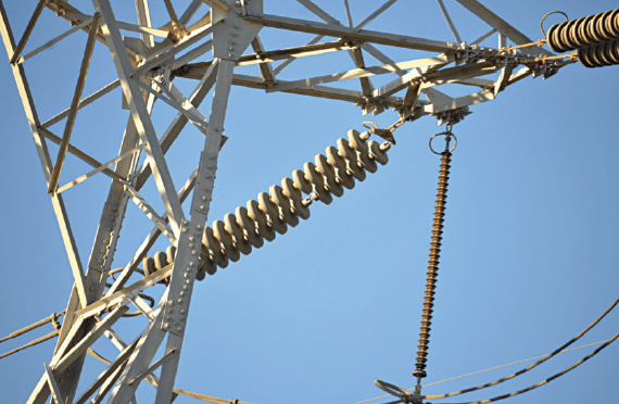
The Italian transmission grid originally used both porcelain and glass insulators. But glass has become the standard since the 1960s and is the only type allowed, except for heavily polluted service areas where either composite insulators or factory RTV-coated cap & pin insulators are mandatory. Experience with glass insulators has been broad and shown very high reliability. For example, some insulators having more than 50 years of service reveal no signs of ageing. On the other hand, corrosion of the cap and of the pin has been observed in harsh service environments due to high leakage current. In such environments, it has even been necessary to periodically also replace towers due to the corrosion. Also, in some cases, there has been discoloring of glass insulators after 30 years of operation but with no impact on electrical and mechanical performance. In Italy, special rings are used on the voltage side of strings with the aim of equalizing electric field, giving more uniformity along the insulator string and limiting radio interferences.
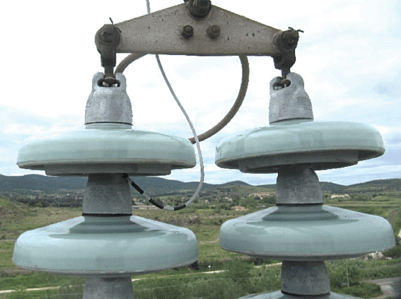
Mention must be made of the risk of presence of internal defects in the glass shell. Even though rare, these can lead to self-shattering under electric field stress. However, should this occur, mechanical performance of the string does not decrease below 90% of its rated value, even should all discs in the string self-shatter. This test is required to ensure a large safety margin should some units shatter during service. Self-shattering is easily detectable by naked eye from afar, without need for special instruments or meters. Consequently, even for high towers, maintenance crews can easily detect shattered units without need for climbing. Fig. 3 shows a naked eye view of a string at about 100 m.

Unfortunately, glass insulators cannot be applied without special precautions in unusually harsh environments. This is because increasing creepage distance beyond a certain level does not yield reliable results – especially in AC where electric field distribution along the string is strongly capacitive. In such a cases, Terna has adopted two solutions: periodic insulator washing and application of grease. Both solutions are costly, especially for lines exposed to marine salt due to vicinity to the coast. In such cases, there have been situations where insulator washing was needed twice a year. Similarly, grease needed replacement every 2 to 3 years, with longer outages needed for this than for washing.
Starting in the late 1980s, the first pilot installations began with composite insulators in heavily polluted areas. However initial field experience was not satisfactory. Then, by the end of the 1990s and early 2000s composite insulators became the standard with broader application in polluted areas. Those years also saw the first pilot installations of factory produced RTV-coated glass insulators. In fact, positive field experience encouraged Terna to apply this technology to extra high voltage lines, becoming the first TSO to install such insulators on the 380 kV grid. Composite and RTV insulators immediately highlighted advantages compared to washing and grease, however uncertainty in regard to end-of-life made it clear that this issue needed to be investigated. Different laboratory tests on both field-aged composite as well as RTV-coated insulators have since begun and involved annual sampling to learn more about ageing processes.
Ageing is different for composite and RTV coated insulators. In general, ageing is usually driven by one main process that prevails over minor processes or by a combination of different ageing processes. Insulators will age from mechanical, electrical and environmental stresses and their synergistic impact on ageing rate become stronger as time in service increases. In the case of porcelain and glass insulators, experience has demonstrated that electrical and mechanical stresses are not or are only weakly related. That means their synergistic result is negligible. On the hard hand, in the case of composite insulators, the synergy between mechanical and electrical stresses is strong. In fact, most of failures of composite insulators are usually mechanical but a consequence of previous electrical stress. Electric field, under specific environmental conditions, gives rise to tracking and erosion, thereby damaging the insulator sheath. The combined impact of electrical and mechanical stresses becomes ever stronger and, should mechanical stress prevail, there will be a mechanical failure (as shown, for example, in Fig. 4). Should electrical stress prevail, there will be permanent electrical failure. Mechanical failures give rise to line drops, but electrical failures can prove difficult to detect. This is due to high and sometimes varying fault resistance, misleading line protection to show an incorrect fault distance after line re-closing.

RTV-coated insulators demonstrate behavior that is similar to porcelain and glass insulators. Mechanical, electrical and environmental stresses all influence ageing rate but there is no or only weak synergy between mechanical and electrical stresses. As such, given the same environmental conditions, ageing of RTV-coated insulators will be less than for composite insulators. This conclusion is confirmed by service experience which shows that failure rate of RTV-coated insulators is in line with that of uncoated glass insulators. For this reason, Terna has decided not to install composite insulators on tension towers, on suspension towers with spans that cross roads, railways, rivers, etc. and also on strategic lines in the grid. In regard to end-of-life, it is also important to note that failed composite insulators completely lose electrical performance, resulting in permanent electrical breakdown.
On the other hand, if RTV-coated insulators lose the enhanced electrical performance offered by the coating, the string is only subject to de-rating, i.e. its electrical performance becomes similar to that of the same uncoated string. This difference in behavior is significant. With RTV-coated insulators a line can be re-energized if contamination level is not too high or, alternatively, operation will continue but with an increased number of expected annual flashover events, Ne. Maintenance is another aspect that is interesting to stress considering both composite and RTV insulators. RTV insulators can be maintained similarly to uncoated cap and pin insulators. For RTV insulators the maintenance actions are cheap since they are limited to naked eye visual check (for self shattering) without tower climbing as per glass insulators and, with a lower frequency, a visual check from the tower in order to assess the coating conditions. Such visual check is performed sampling some towers along the line.
Based on local experience, large damage on a coating (as in Fig. 5) does not alter behavior of the string under contamination if such damage is limited to only a few units. Moreover, there have never been cases of widely damaged strings, even after more than 10 years of operation. In this respect, it is important to note that in-factory coating yields a higher level of reliability than field coating in terms of long lasting adhesion of the coating. As such, RTV line insulators are allowed to be installed on the Italian high voltage grid only if they have been pre-coated in the factory. Composite insulators are much more expensive for maintenance than RTV insulators. Their intrinsic characteristic to abruptly lose their mechanical or electrical performances imposes a different approach on maintenance: yearly visual inspection from the tower together with camera able to assess both infrared and ultraviolet emissions and electric field distribution along the insulator to detect hidden critical defects (see Fig. 6) are an obliged step. As far as DC lines are concerned, they are usually very long and then reliable and easy-to-detect faulted insulator solutions are necessary. For this reason, TERNA decided to use glass insulators and pre-coated glass RTV insulators only.
Recently, a limited pilot installation was started on a 132 kV line equipped with half-coated RTV glass cap & pin insulators (see Fig. 7). If found to be reliable, this solution could prove an economical alternative to fully coated insulators for application in heavily contaminated areas, providing a solution somewhere between uncoated glass and full coating. Finally, a new natural contamination laboratory called LANPRIS went into operation in late spring of 2017 and is located in a contaminated area near the sea in south Sardinia. Here, there is a combination of heavy marine pollution due to year round strong wind and heavy industrial pollution from iron and steel industries. Terna uses this facility to test insulators stressed at different specific creepage distances so as to gather more information on ageing processes.
Substation Insulators
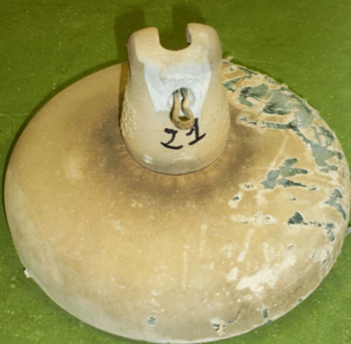
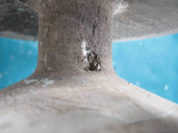
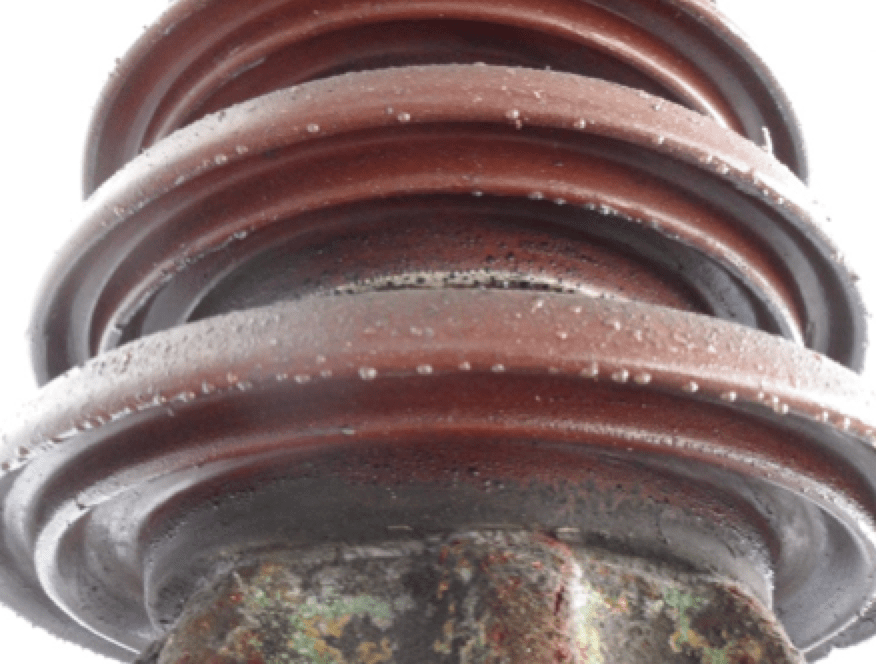
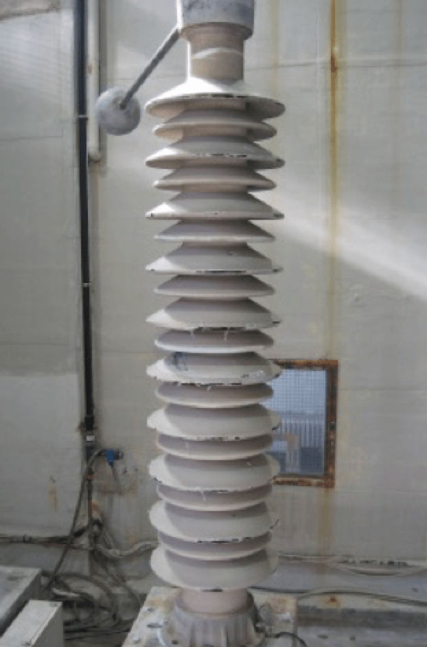
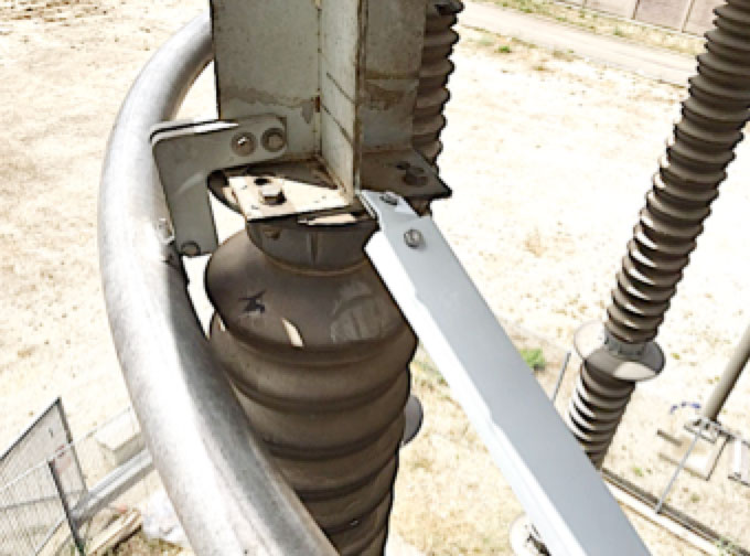
Terna has always used brown glaze porcelain for solid core post insulators (e.g. for busbar, bay and switchgear supports) as well as hollow core insulators (e.g. for current and voltage transformers, circuit breaker, surge arresters, transformer bushings, cable terminations, etc.). The first installations of composite hollow core insulators started in the 1990s. Today, due to safety and security against risk of explosion due to internal arcing, composite hollow core insulators are mandatory for all new installations and also in cases of refurbishment/replacement of old porcelain insulators. In this respect, composite hollow insulator must pass specific Terna tests, e.g. a 2000-hour test (also applicable for composite and RTV-coated line insulators) and a recommended DC inclined plane test. The latter is mandatory, even for hollow core insulators intended for AC applications. Moreover, in the case of composite insulators, Terna requires a specific maximum tangential electric field on the insulator surface. Also, for high temperature vulcanized (HTV) materials, at least 45% of the weight must be alumina trihydrate (ATH) filler. In addition, artificial pollution testing is not accepted on hollow core insulators alone. As such, to cope with the need for frequent insulator washing at substations located in extremely polluted environments, Terna has resorted both to greasing and to field RTV coating of porcelain. The former, although cheaper, has a more frequent replacement cycle. The interval between consecutive replacements of the grease relates to level of contamination but ranges from 3 to 6 years. Fig. 8 shows a post insulator that has been greased. By contrast, on site RTV coating, can reduce station section outage time since it is assumed that re-coating is necessary only after about 10 years (assumed end-of-life). Fig. 9 shows a busbar porcelain post insulator that was coated in the field and laboratory tested after 7 years of operation. Fig. 10 shows a field coated porcelain post insulator supporting the smoothing reactor of the Italy-Greece HVDC Intertie to cope with harsh environmental conditions at the Galatina Converter Station.

Conclusions
Outdoor insulation dimensioning is not an easy process since so many variables shall be taken into account and most of time the uncertainty on the values in some of such variables requires caution. For this reason the statistical methods can better manage uncertainties and can lead to a robust estimation of expected flashover events per year. Although the behavior of different kind of insulators or strings of insulators under different laboratory contamination levels can be reasonably inferred thanks to the wide number of performed tests, the estimation of the insulator contamination, during for example the year, is still a difficult task for different reasons:
• measurements performed in field are usually small in number and hardly extendable to a wide territory;
• theoretical models can perform fine in certain areas and bad in others;
• even if the environmental contamination level is well estimated, specific models shall be used to convert such data to insulator surface contamination.
• Terna has gathered a lot of experience directly from field operation of its very large grid (72,845 km of HV/EHV lines and 855 HV/EHV stations) and this is a vital cog in the insulation dimensioning machine since it adds a confidence interval to the final insulation dimensioning result.
Overhead line outdoor insulators and station insulators although they have so many things in common, they shall be treated separately since the peculiarities of each one makes the difference in the creepage selection.
The Italian overhead high voltage lines are widely insulated with glass cap and pin insulators with very satisfieng results both in terms of life span and maintenance: a robust solution. On harsh environmental polluted areas both composite and RTV pre-coated glass insulators are used. Although composite insulators can give very good results, it is quite complicated to predict their end-of-life since in some case, abrupt failures have been recorded. Consequently specific countermeasures shall be adopted in order to not incur over critical conditions. RTV pre-coated glass insulators have the advantage to be considered as a sort of improvement of glass insulators for heavy polluted areas: very high electrical and mechanical reliability, residual electrical performances at the end-of-life (in the worst condition the electrical performances are similar to those of naked glass insulators), a robust solution for the grid. The Italian stations are equipped mostly with brown porcelain insulators (busbar post, bay post, switchgear insulators and hollow core insulators), but since some year in the new station hollow core insulators (all the apparatus equipped with hollow core insulators) shall be of composite technology. This decision has been taken in order to increase safety and security against internal arcing faults. In harsh environmental polluted area, grease and in-field RTV coating on porcelain insulators are used to reduce the risk of failure. Continuous research and field returns are of paramount importance for the creepage selection and then for the reliability of a grid.