To achieve the optimum balance of cost and performance, accessories for MV and HV cables are increasingly being produced using tailor-made polymeric materials as well as specialized manufacturing processes. At the same time, developments in cable systems themselves are also impacting the design of accessories that are being developed for use both now and in the future.
This INMR article from 2012, a consolidation of contributions by Jack Qin (China) and Jens Lambrecht (Germany) of Wacker, Rainer Röder of Gardy Technology, Gerhard Mais of Vogel Moulds and Machines and Samuel Ansorge, provided an overview of market trends for cable accessories as well as key properties required of the elastomeric materials used to manufacture them.

Overview
Although one still finds a variety of alternative cable technologies in service worldwide – from gas-insulated to oil-filled – cross-linked polyethylene types have begun to dominate new applications since the late 1980s. At the same time, accessories for these XLPE cables have been undergoing considerable development and improvement over that period, especially during the past decade. The first generations of accessories, for example, were liquid-filled while today more ‘environmentally friendly’, dry types are gaining in preference.
Other features demanded these days of cable accessories include flexibility and ease of handling. For example, terminations for GIS or transformer applications are normally installed on-site, meaning that the GIS or transformer would then have to be completed and tested there as well – something that is not always convenient. Recently available pluggable terminations eliminate the need for additional on-site testing and also offer advantages in terms of installation – independent from that of the GIS or transformer that need only be equipped with pre-installed sockets. Customers can then decide later in the project whether a cable or overhead line termination is more suitable.
Pluggable bushings for overhead line connections as well as more compact pluggable arresters are now also available, while connections can be made in every cable position – whether horizontal, vertical or somewhere in-between.
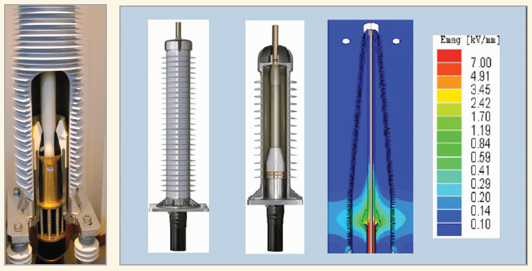
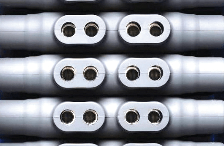
The ‘heart’ of a pluggable connector system is the socket, which must be capable of providing field control and designed to meet the requirements of different applications. While it will be placed into GIS and transformers, the socket operates in oil or SF6 that have different permittivity factors. Therefore the design of the field control elements must be capable of covering a range of different field strengths, depending on application.
Future developments when it comes to cables will concentrate on higher voltages, larger cross-sections and new applications. The challenge here is that while cables are already available up to 800 kV, production, transport and handling for such voltages are all very demanding. Achieving increased current capacity will require cable conductor cross-sections to increase from the 2500 mm² that is fast becoming common to 3000 mm² or even more .
The trend toward renewable energy sources is also driving a growing need for DC cable links up to 300 kV to connect offshore wind farms to the grid. Accessories for such applications will require different material properties and manufacturers will have to gain the relevant field experience to develop products suited for this emerging market.
Trends in Cable Accessories
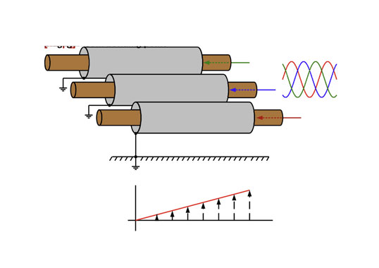
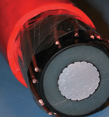
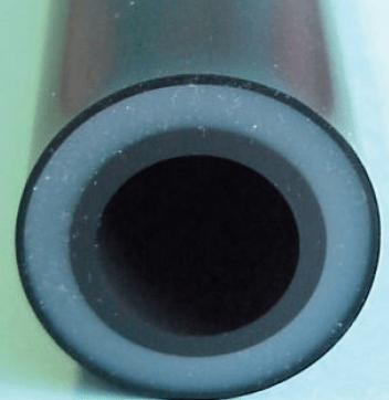
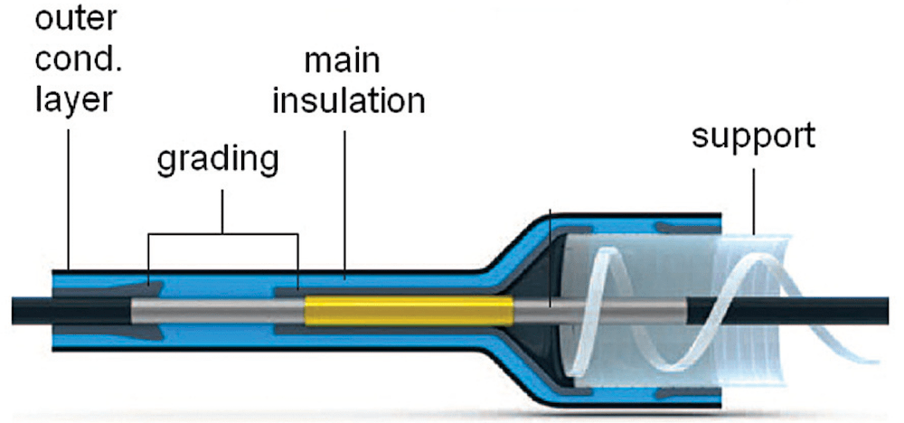
Most MV and more and more HV cable installations today are insulated using extruded polyethylene.

Here, the inner aluminum conductor is surrounded by a grading layer made from electrically conductive polyethylene. The main insulating layer and outer conductive grading layer are made of polyethylene, while the outer conductor is covered by an external sleeve.
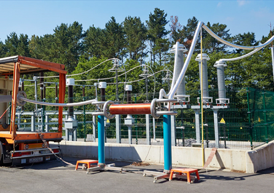
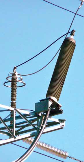
The use of medium and high voltage cables of different lengths requires their connection and integration into substations and overhead lines. It is here is that cable joints and terminations find main application.
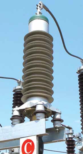
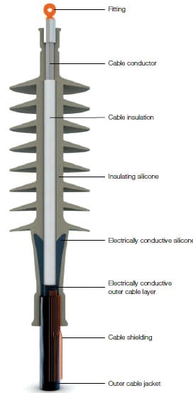
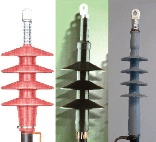
Whenever a cable is connected to an overhead line or an electrical installation, the outer conductor and grading layer must be removed and the cable insulation covered by a termination. The main tasks of the termination in this regard include:
• Grading the electric field at the end of the removed outer grading layer;
• Covering the polymeric insulation;
• Providing the external creepage needed for the pollution conditions of the service environment.
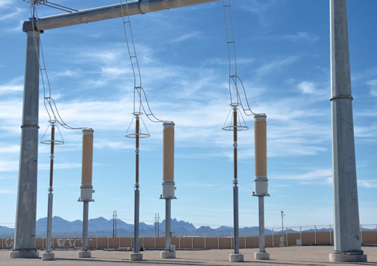
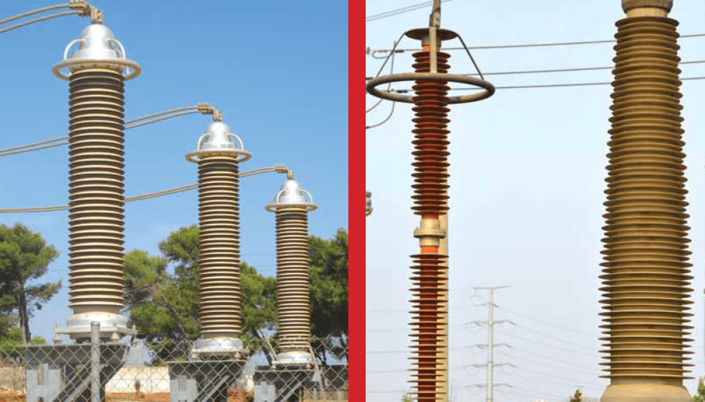
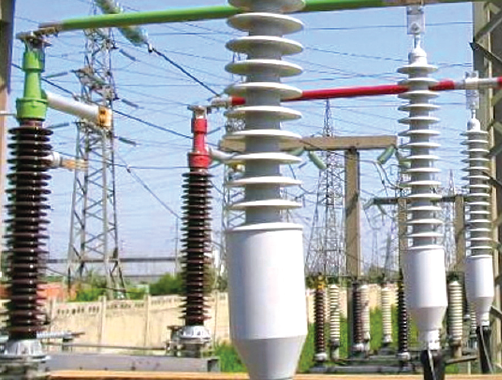
At the MV level, terminations have virtually all been made of polymers such as EPDM and silicone for decades and a similar transition to polymeric housings seems to be the trend at higher voltages as well. Silicone-housed HV terminations offer a number of advantages over porcelain including increased safety, less environmental risk and faster installation. For example, depending on voltage class, the time required to install such terminations has been estimated to be as much as 20 percent less than for porcelain housings.
When it comes to MV terminations, there has been steady process of design improvements over the years resulting in more cost-effective products with slimmer profiles. Similar advancements in field grading technologies are expected to result in slimmer HV terminations as well
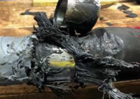
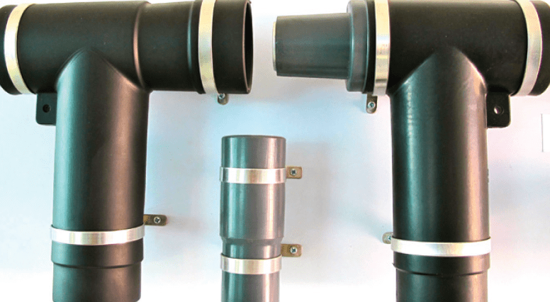
But cables are not connected only to an overhead line and other installation. More often than not, the connection is to another cable such as when a damaged section must be repaired or a branch needs to be made. This can be accomplished using different types of joints, whose principal functions include:
• Providing proper insulation, especially with respect to the radial electric field;
• Grading the electric field at the ends of the cable’s outer grading layer;
• Covering the connector while also providing the required mechanical strength.
New, compact and more cost-effective solutions can be found in the area of cable joints as well.
As is the case for cable terminations, the potential for more rapid and less costly installation is now also driving development of pre-molded joints for HV applications. These are increasingly replacing pre-fabricated joints since there are fewer parts and a built-in compressive force is included that eliminates the need for separate compression apparatus on site. There are fewer parts as well, which makes them less costly to produce.
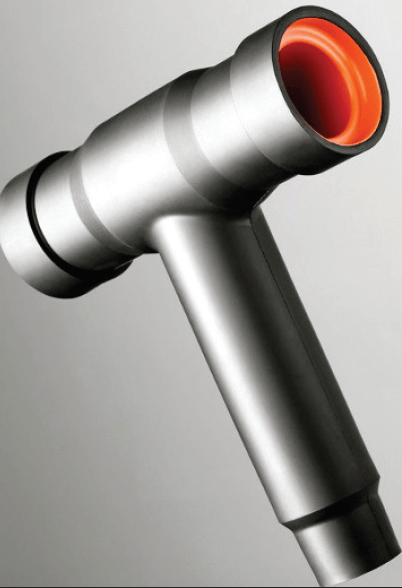
Apart from these types of developments in terminations and joints, a third type of cable accessory – the connector – is now also offering improved and more cost-effective cable solutions. Connectors are used to plug cables into electrical equipment, such as switchgear, transformers, measuring devices, etc. Accurately fitted parts of molded silicone are connected to epoxy resin counterparts to achieve a safe and reliable connection that can be quickly separated whenever necessary.
The number of connector designs and added auxiliary equipment is very broad. For example, plug-in arresters can be mounted to ground lightning impulses and this same technology can even be adapted to produce connectors for busbars.

Material Requirements & Properties
Elasticity, erosion resistance and long-term stability under electrical stress are among the most important characteristics required of the materials used to manufacture cable accessories.
In the case of joints, reliable electrical interfaces with epoxy fitting parts are guaranteed because of silicone’s pliable nature as well as its inherent ability to generate and maintain lasting mechanical pressure.
In this regard, the superior electrical insulation properties of silicone elastomers, combined with the fact that they resist ageing and feature stable long-term elasticity, is fast making them the material of choice for many cable accessories. For example, in the case of joints, reliable electrical interfaces with epoxy fitting parts are guaranteed because of silicone’s pliable nature as well as its inherent ability to maintain lasting mechanical pressure.
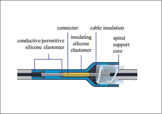
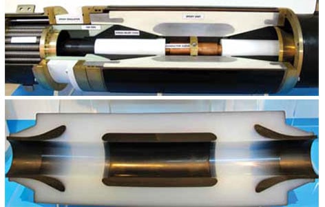
The latest generation of dry type cable joints and terminations share a common feature – namely the insulating component including field control elements. This ‘heart’ of every dry type accessory is normally made of silicone and the parts pre-fabricated and usually tested at the facilities of the manufacturer.
These types of requirements are increasingly being met by specialized grades of silicone elastomers and the use of the right grade for each application is important both in terms of service performance and optimized manufacturing. For example, stateof- the-art field grading for the MV range can be achieved using a silicone with a relative permittivity of about 15. Conductive grades are then used for field grading in HV applications.
Similarly, erosion resistant grades of liquid silicone rubber (LSR) or high consistency rubber (HCR) with hardness in the range of 25 to 40 Shore A have been found ideal for cable terminations. Moreover, their high elasticity allows easy assembly without need for additional tools.
The most noteworthy benefit of silicone elastomers when it comes to outdoor cable applications such as terminations (especially under polluted conditions) is their intrinsic hydrophobicity. This property is already well understood by the power industry and allows for more economic designs with shorter creepage and less maintenance requirements in comparison with materials such as porcelain.ss maintenance requirements in comparison with materials such as porcelain.

Manufacturing Needs
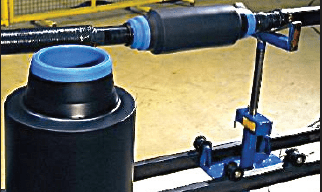
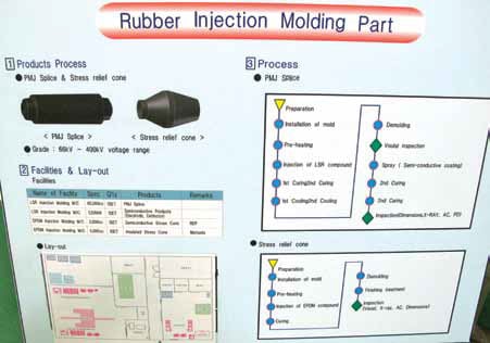
Silicone elastomer joints are generally manufactured either by a variety of molding processes or by multiple-layer-extrusion technologies.
Cable accessories for all voltage levels and applications these days are increasingly based on silicone, featuring stress cone inner insulation with non-conductive silicone and then the electrically conductive silicone. When it comes to cable terminations, there is either a direct over-molding of the outer insulation or alternatively use of a hollow core insulator housing. In the past, these types of accessories were manufactured mostly using RTV silicone. However, due to pressures to reduce costs and processing times, use of LSR is now increasing. This material has shown good results from a cost perspective as well as in electrical and mechanical design. For example, bonding between the different silicones – conductive and non-conductive – can be achieved through the material’s intrinsic properties, without need for any external bonding agent or primer.
Different manufacturing techniques are used, often depending on voltage level of the accessory. For example, a horizontal mold parting line on the silicone stress cone at MV levels is generally accepted. In such a case, typical manufacturing equipment consists of dosing and mixing units for a two-component LSR in a ratio of 1:1. A standard clamping machine (as also used for MV epoxy parts) is close by. The sleeves to be manufactured have a dedicated manufacturing process while the molds too feature a specialized design. The production area can then be set-up with a special venting system as well as closed loop manufacturing and testing processes.
Cable systems required by power utilities are moving toward higher voltages and, with this trend, the requirements from the viewpoint of material electrical properties and automated production processes only increase. One particular design of cable termination with stress cone and external insulator, for example, required a more specialized manufacturing set-up since the thickness of the silicone would normally have required a long vulcanization time. But in this case a patented system called AVT was used whereby the two components of the silicone were pre-heated in a heat exchanger and this resulted in a 30 to 50% shorter curing cycle. Any unwanted back grinding was also minimized and this reduced quality control costs as well.
In general, as the cable industry receives more and more orders for cable joints and terminations at HV voltages, e.g. up to 500 kV, optimizing production of stress cones that may require up to 80 liters of silicone will become a growing need. Using RTV silicone or even LSR in a non-optimal process could take many hours and it is therefore becoming ever more important to implement automated processes. Their common basic goal is to reduce overall cycle time by integrating each of the individual process steps for the silicone body into one controlled manufacturing process, including: mold preparation; pre-heating; mold filling with LSR; controlled curing; cooling the mold to room temperature; opening the mold; automatic extraction of the core from the silicone body; and cleaning the mold in preparation for the next cycle.
In order to achieve high product quality when it comes to large volume HV cable accessories, optimizing process parameters will be critical, meaning controllable inner mold pressure (with no back grinding) and very good material flowability. This way the final accessory will offer the best mechanical and electrical properties as well as the perfect adhesion between the field control part and the insulating silicone.

Summary & Outlook
Applications for cable accessories these days are becoming ever more demanding with respect to mechanical properties as well as the compression set of the materials being used. At the same time, voltage levels are getting higher while overall life cycle costs (including raw materials, production, field assembly and maintenance costs) are all under pressure to be as low as possible. In this type of environment, one type of accessory should ideally be applicable over a range of different cable cross sections.
For the future, as cable voltage levels climb, there will be a growing need for further tailor-made solutions to manufacture large silicone-based accessories in the optimal way. In this respect, there will also be a need for ongoing co-operation between the industry that offers cable terminations and joints, manufacturers of the related production equipment and the silicone material suppliers.