As the rate of application of composite insulators on overhead lines continues to spiral upward, accurate methods to monitor them for critical damage have taken on prime importance. Apart from the obvious impact on reliability of networks, trustworthy condition assessment is also important to assure the safety of maintenance personnel prior to live-line work. Unfortunately, no single diagnostic technique has emerged that can identify all possible types of damage in a composite insulator. A variety of complementary tools and procedures must therefore be employed. Those that can be applied in-service are of greatest interest to power system operators since inspections can be conducted with lines energized. This edited past contribution to INMR by Dr. Igor Gutman, now with Independent Insulation Group in Sweden, reviewed and compared alternative techniques.

Visual Inspection
Visual inspection is probably the most common technique for assessing the state of composite insulators. It is generally effective since many types of surface damage are easily observed during climbing inspections – or even from the ground, a helicopter or bucket truck using binoculars. A number of practical guides have emerged to assist maintenance staff by providing detailed descriptions of typical defects that can occur along with selected photos of what specifically to look for.
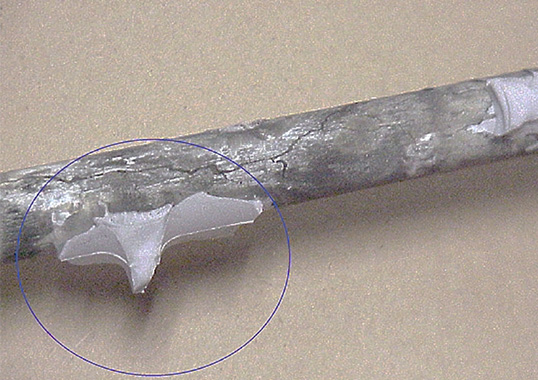
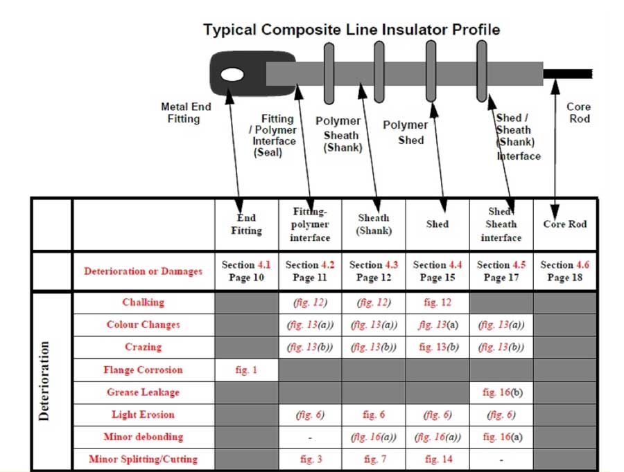
During visual inspection, utility maintenance staff must examine the full length of the installed insulator. To make the process easier, the basic design of a composite insulator is divided into ‘regions of interest’ (see Fig. 1). Reference tables and profile diagrams are also included so that photos and definitions of interest can be located quickly with respect to any visible deterioration or damage. Examples of such photos are shown in Fig. 2. To perform visual inspection, the inspector should ideally be as close to the insulator as possible or, alternatively, employ binoculars or a telescope.
Instrument Based Diagnostics
IR thermography from helicopters is commonly used to verify the condition of conductor joints along an overhead line. It therefore seems logical to also inspect composite insulators during the same flyover. In fact, experience has demonstrated that IR inspection generally results in a higher detection rate of incipient problems than do other instrument techniques such as UV, acoustic or E-field detection.
Extensive research has been conducted in past years that combined laboratory, field and in-service inspection of composite insulators with known internal defects. This work resulted in practical guidelines for IR helicopter inspections that were later verified under real operating conditions. Nevertheless, there is a need to continue accumulating information and guidelines recommended: “any polymeric unit showing an internal temperature rise should be replaced and sliced open to verify the extent of internal defects”.
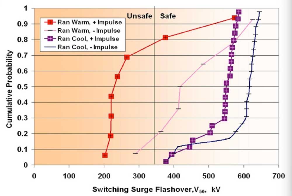
The effectiveness of IR detection has been confirmed during another program where 39 composite line insulators with deliberately placed internal defects were tested under switching impulses (SI). Preliminary investigation had shown that 11 of these insulators ‘ran hot’, i.e. displayed elevated temperatures during IR inspection. Subsequent diagnostics using positive SI then confirmed that most were indeed damaged (see Fig. 3). On the other hand, all 22 insulators that ‘ran cold’ successfully passed the SI tests. Based on this work, it was concluded that, for the specific types of defects investigated, IR thermal detection is superior to visual inspection or other techniques.
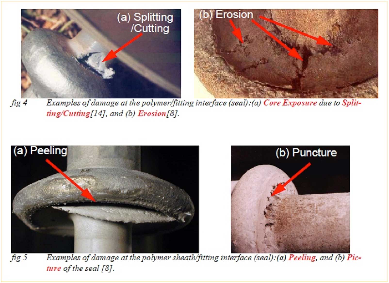
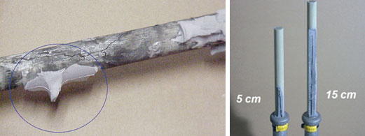
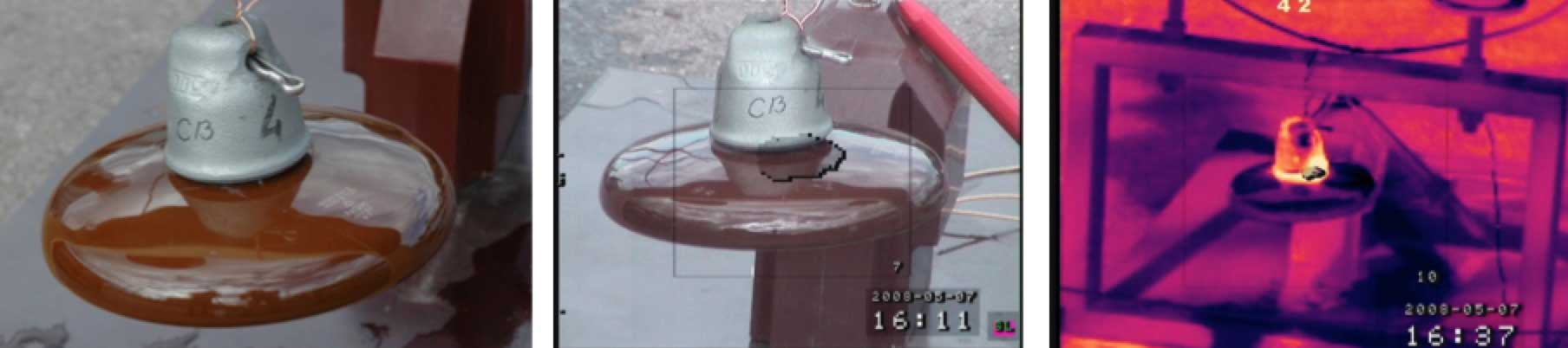
Moreover, it has also been demonstrated that helicopter-based IR inspection of composite insulators is effective even under cold and windy conditions. This correlates with past experiments conducted on defective insulators, presented in Fig. 4 (left). Such defects had been basically ‘invisible’ to corona cameras as well as image intensifiers, yet their heat was clearly detectible. Still, experience with IR detection has not always been consistent. One explanation is that the relative success in detecting an internal problem may relate to the specific type of defect being investigated. For example, some testing involved defects intended to simulate conductive or semi-conductive tracking marks or moisture ingress (as in Fig. 4). In other investigations, however, different internal defects were created through deliberate cracks in the rod or by placing channels between the rod and the rubber that were filled with lightly conductive moisture. Another method to simulate internal defect involved placing a semi-conductive strip of RTV material between the rod and rubber sheath.
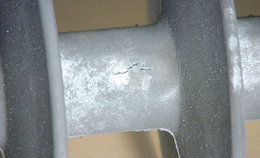
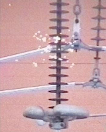
Defects were clearly detectable from a distance of about 30m and the resulting overheating was between 2°C and 40°C, depending on type of defect. In other research, the defects introduced during manufacture were tracking marks, created by 5-10 mA currents on the surface of the rods without primer under humid conditions. These types of defects were also easily detected in the laboratory but the overheating in this case was about 8°C. Basically, as long as a defect is hidden inside the insulator and produces heating, IR can be considered the most effective diagnostic method. However, once the internal defect ‘opens’ and starts to produce corona activity (see Fig. 5), ultra-violet diagnostics become preferable.
[

Light Amplification Devices
Night Vision
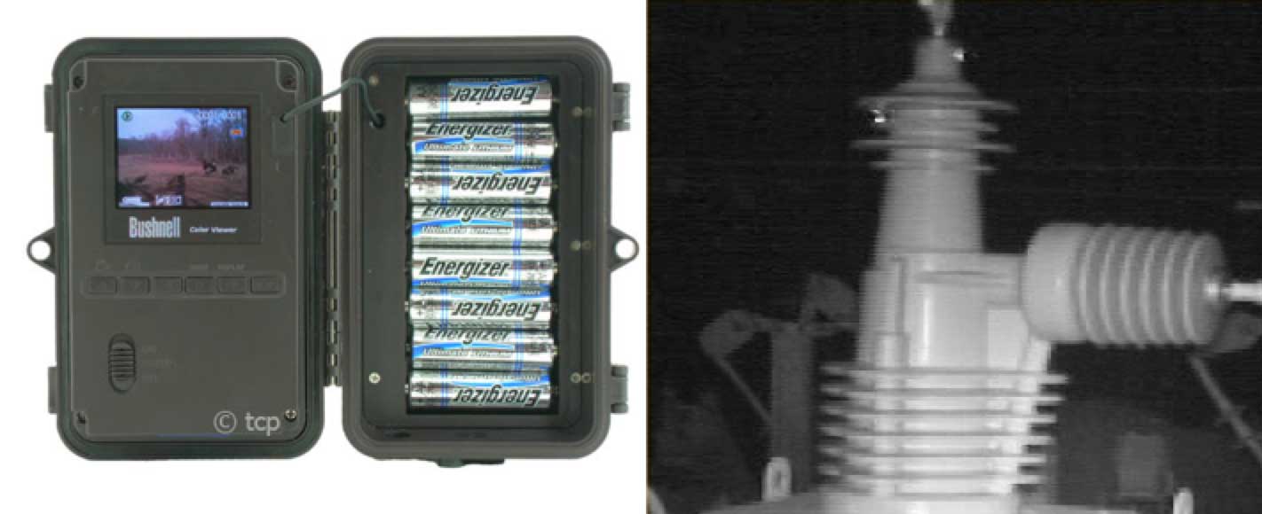
Observations of insulators at night with an image intensifier (normally having a light gain of at least 20,000X) can reveal surface discharges or corona activity. But development of these devices was only a first step in light-amplification diagnostics since power companies prefer to conduct insulator testing during the day. Such devices later appeared on the market as daylight UV cameras or simpler commercially available day or night cameras used for inspecting insulators. A past example came from Eskom in South Africa, where a camera originally intended for observation of creatures was used to detect discharge activity along insulators. This camera, equipped with motion and infrared detectors, automatically starts recording and can therefore also be used to investigate bird-induced outages (see Fig. 6).
Daylight Vision (UV)
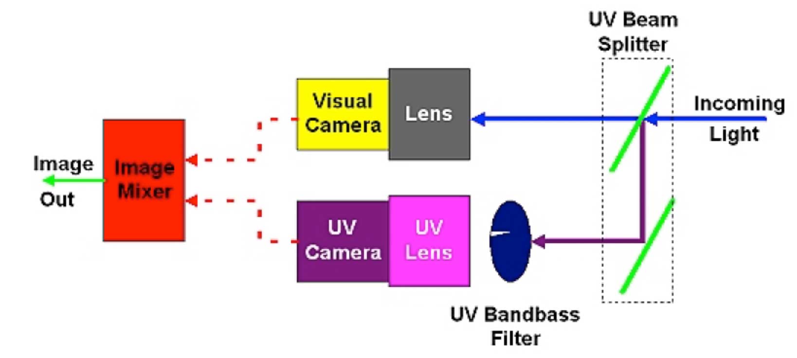
Daylight UV cameras allow corona to be identified during the day as well as at night by blocking out sunlight and then superimposing an image of the corona over the object being inspected. Although corona discharges can be seen in daylight, it is impossible to determine their exact location without the ability to overlay the image of the corona over that of the affected insulator or structure. Such cameras therefore employ bi-spectral imaging using a UV beam splitter to divide the incoming image into two. One image is sent through the solar blind filter to eliminate sunlight, then through an image intensifier and a charge-coupled device. The other is sent through a standard video camera. The two are then processed and combined in a mixer, resulting in an image of the corona exactly as it appears on the structure or component under investigation. This makes it possible for maintenance personnel to pinpoint the exact location of corona and take corrective action (see Fig. 8).
Combined UV & IR Vision (Multi-Camera)
The multi-camera allows studying electromagnetic radiation emitted in the visual, infrared (IR) and ultraviolet (UV) wavelengths. Together with its low weight (2.6 kg) and portability, the main benefit is the possibility to easily combine UV/visual or UV/IR images. The device resembles a standard video camera (as in Fig. 9 left) and operates with three 2D light sensors having different spectral sensitivities (IR, UV and visual light) – all combined with electronics for control and suitable optics. Signals recorded are presented as video or still images after processing. The visible and UV channels have a common line of sight, while the IR channel has a separate aperture. UV mirrors are used to split and deflect light onto the UV detector. To allow the high level of amplification needed, collected light is filtered to extinguish wavelengths outside the band of direct interest.
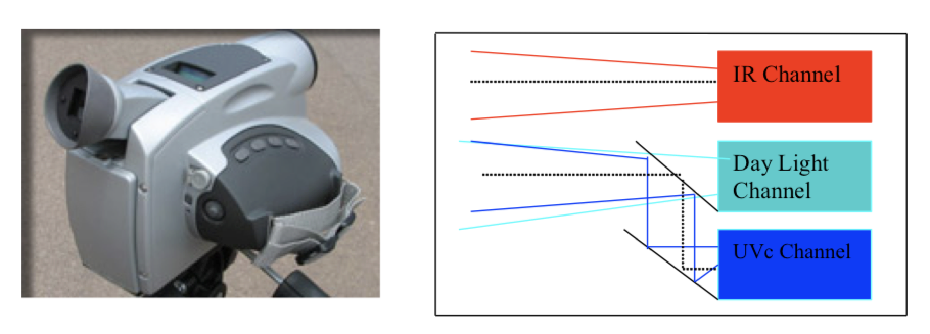
The capabilities of the camera for practical measurements in service were confirmed during field tests performed in Sweden. From these, it was obvious that the camera is a flexible tool facilitating identification of problems that give rise to corona detectable by emitted UV radiation. At the same time, the IR channel allows identifying problems resulting in an abnormal temperature increase. Such a camera is recommended more for use from the ground (e.g. for inspecting substations) since helicopter fly-by inspection would likely require more sensitive techniques.
E-Field Measurement
When a composite insulator is electrically defective, the electric field changes in the vicinity of the defect. A portable, manually operated diagnostic apparatus has been designed for this purpose and is used with the insulator still in service. The principle of operation is based on the AC axial electric field along the insulator. The measurement and recording unit is U-shaped with a mounted field probe. Faulty regions of the insulator are recognized by noticeable decrease in AC electric field.
[

Comparison of Ground/Air Applications
As shown in Table 1, most diagnostic methods discussed above can be performed either from the ground or from the air.
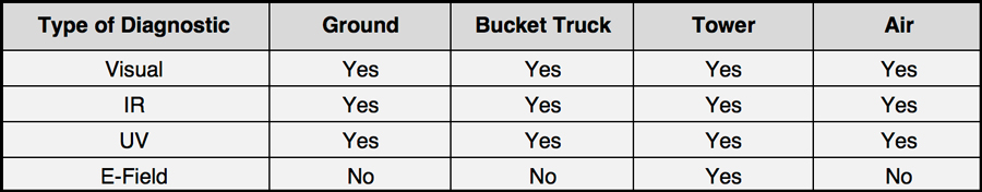
Normally, most aerial inspections of overhead lines are performed by helicopters moving at speeds of at least 20-30 km/h. Different power companies employ different techniques, from only fly-by to hovering at the tower. Other flying apparatus, such as small planes, gyroplanes or even dirigibles can also be considered.
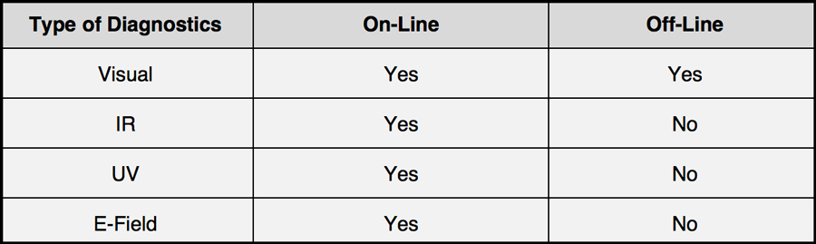
Comparison of On-Line/Off-Line Applications
In order to generate heat (detectable by IR) or corona (observable by UV), the insulator being inspected should be energized. In the case of certain defects, such as flashunder, the line might be switched off and not be able to be re-energized due to the failed insulator. In such a case, only visual inspection can and should be performed (see Table 2).
A theoretical alternative, as proposed by some in the industry, is to equip insulators with some kind of flashover indicator, e.g. a bright red colored glass insulator with special properties so that it would explode if the E-field along the ‘protected’ composite insulator increases between 20 and 50%.
Diagnostics Before Live-Line Work
A specific of all live-line work (LLW) is that the critical defect size depends on the configuration and maximum slow front voltage value assumed during LLW. Investigations have indicated that conductive type defects of up to about a third of the insulator length are still acceptable in this regard. Moreover, even if such defects were originally internal, they would most likely induce some visible surface deterioration (as in Fig. 5). Therefore visual inspection should always be the first option, even if it could lead to rather conservative conclusions. Quantitative condition assessment of composite insulators can be performed using UV/IR cameras while E-field measurements can serve to increase the level of information in specific cases. Given this, it should be possible to safely carry out LLW on overhead lines, whether equipped with ceramic or composite insulators.
Applicability Diagnostic Methods to Different Types of Insulators
Diagnostics of glass cap & pin insulators is relatively easy since insulators usually fail by shattering and the damaged stubs can be identified by visual inspection using binoculars. The matter is more complicated for porcelain cap & pin insulator strings. In this case pinholes through the porcelain shell and/or between the cap and the pin cannot be visually identified. Detection of defective units requires diagnostics, such as so-called ‘buzz testing’, E-field measurement, UV or IR detection. Taking into account that ‘buzz testing’ is no longer in use at many utilities, the same diagnostic methods are generally applied for porcelain as for composite insulators.
Summary
The main diagnostic techniques for detecting defective insulators (especially composite type) have not changed appreciably and include: visual inspection and hydrophobicity assessment; IR detection; UV detection; and E-field measurement. While visual inspection and hydrophobicity assessment are already quite well standardized, the other methods rely on experienced professionals, especially when it comes to interpreting results.
There is no single optimal method for the diagnostics of insulators. IR thermography and UV detect principally different physical properties (i.e. heat and enhancement of electric field in the form of corona). A combination of the two or use of a multi-camera will therefore provide maximum data for the remote inspection of composite insulators.
Most of these diagnostic methods are applicable from the ground or from a helicopter used for aerial inspections or indeed a variety of aircraft. All methods should be performed when the line is energized, however, in cases where this is not possible, special self-destructive devices can be considered. Damaged glass insulators can be easily detected visually, while in the case of porcelain insulators the same basic diagnostic techniques are valid as used for composite insulators.