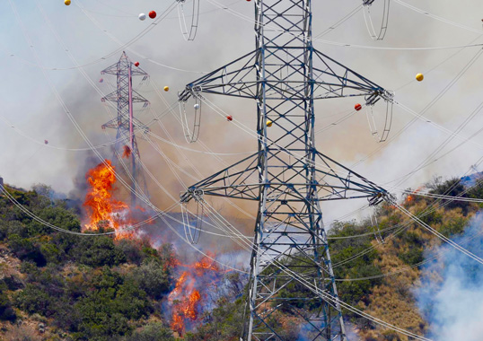
Understanding which parameters can become degraded or critically deteriorated if an insulator is exposed to heat and fire depends on exposure time as well as type and design of insulator. More challenging is to consider potential collateral damage to an insulator even if not necessarily directly under a wildfire yet still close enough to be exposed to its heat. Apart from direct risk of failure related to the heat, it is important to evaluate any possible weakness induced in the insulator that could then become the root cause of a later line drop and fire.
This edited past contribution to INMR by Jean Marie George and Dr. Sandrine Prat at Sediver addressed heat sensitivity of typical insulator designs used on overhead distribution and transmission lines as well as risk of degradation in performance, even if still operational after wildfire.

Key Design Features of Overhead Line Insulators with Respect to Thermal Resilience
Temperatures can fluctuate dramatically during a wildfire and it is difficult to precisely know the direct temperature of an insulator in contact with the fire as well as the duration of the event. This section will therefore look into the key properties that can be impacted by heat in the case of both polymeric and ceramic type insulators based on their inherent design features.
Composite Insulators
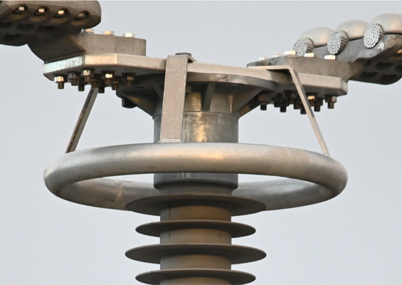
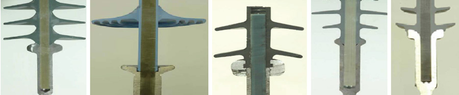
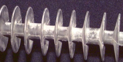
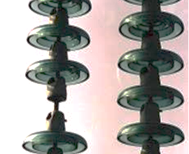
Composite insulators exist in a large variety of designs (see Fig. 1) and are made of organic materials that have temperature limitations. The large diversity of possible designs and materials used to make these types of insulators greatly increases the complexity of any long-term evaluation.
There are three main design features to look into as described and discussed in more detail below.
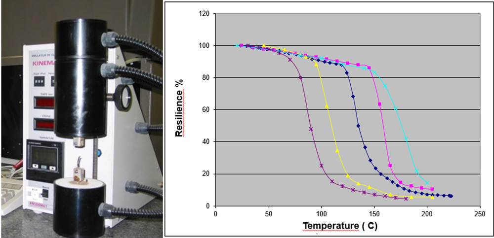
1. The fiberglass rod is made of resin reinforced by glass fibers. Resins used for insulators can be polyester, vinylester or epoxy. The strongest and best performers are those with epoxy resins. Resins are defined by a thermal set point, Tg (softening point), above which the resin begins to progressively lose mechanical strength. This characteristic can be established by Differential Scanning Calorimetry (DSC). The mechanical weakening of the interface between the glass fibers and the resin in the rod, and which is key for mechanical strength, can also be measured through a torsional strength test on a small slice cut from a rod. Fig. 2 shows the test equipment and results obtained from commercially available fiberglass rods used to manufacture composite insulators. The mechanical resilience of the samples decreases with temperature. Moreover, sensitivity to heat is the direct result of the resin’s chemistry.
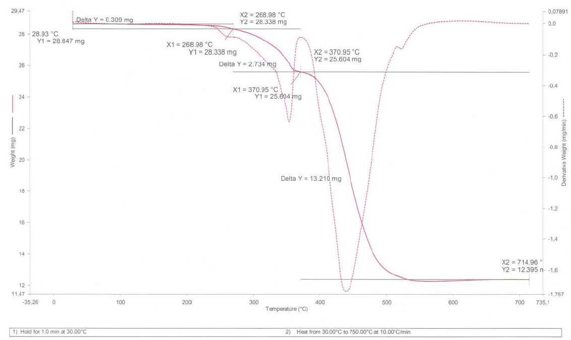
2. The housing, typically silicone rubber, is a material designed in most cases to chalk and not burn. While silicone rubbers can exist with numerous chemistries, the most popular silicone compounds contain fire retardant filler such as alumina trihydrate (ATH). To achieve better erosion and electric tracking resistance, the amount of this additive in the silicone is usually above 45% and can be measured by Thermo Gravimetric Analysis (TGA). Fig. 3 shows the graph obtained by TGA of a silicone rubber. A decrease in weight during the test is typical of the loss of water from the ATH molecule during heating. Normally ATH decomposes around 250°C (482°F). Silicone rubber subjected to excessive heat will display a white powdery surface (see Fig. 4).
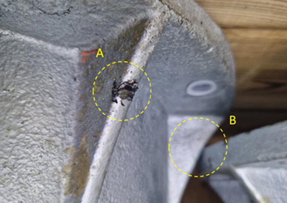
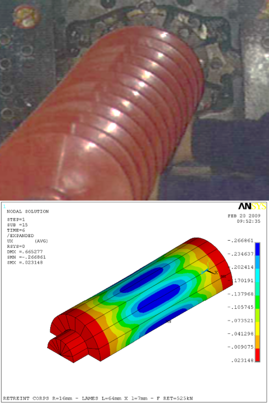
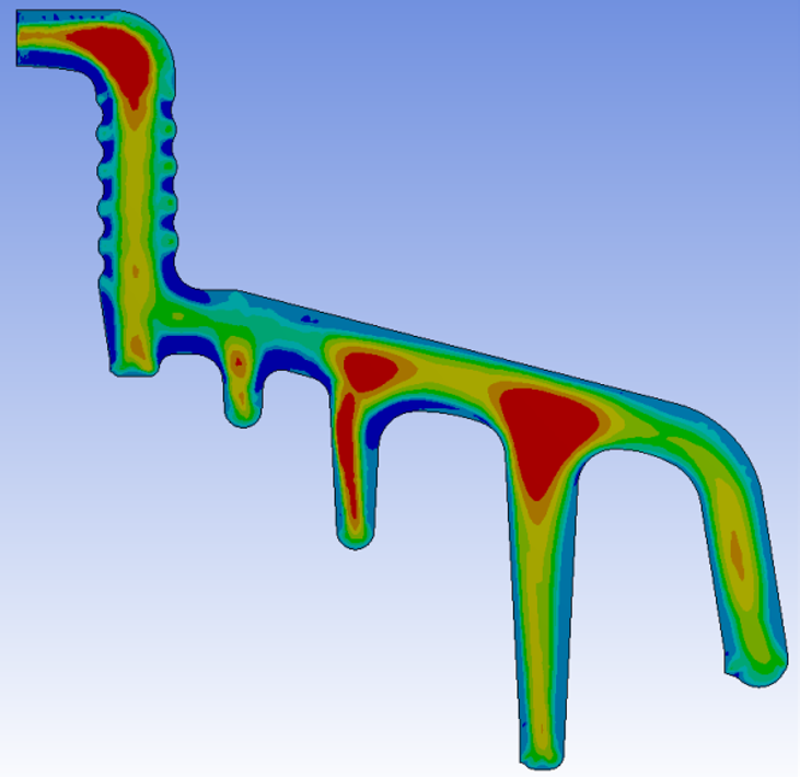
3. The end fittings of modern composite insulators are normally crimped by compression (similar to cable joints). The key to this process is ensuring sufficient pressure through the end fitting (which is made of steel, cast iron or aluminum) to ensure a sufficient grip on the fiberglass rod, which is not a metal. To avoid risk of thermal relaxation during molding of the rubber housing onto the core, end fittings are usually crimped after the housing is in place. Fig. 5 shows this process and the compressive stress distribution onto the rod during crimping, which must avoid any possible damage such as cracks. This remains a highly sensitive operation in spite of compression sensors intended to control the process.

Porcelain Insulators
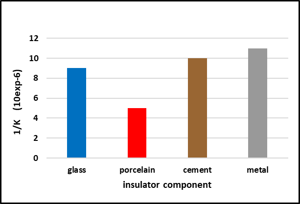
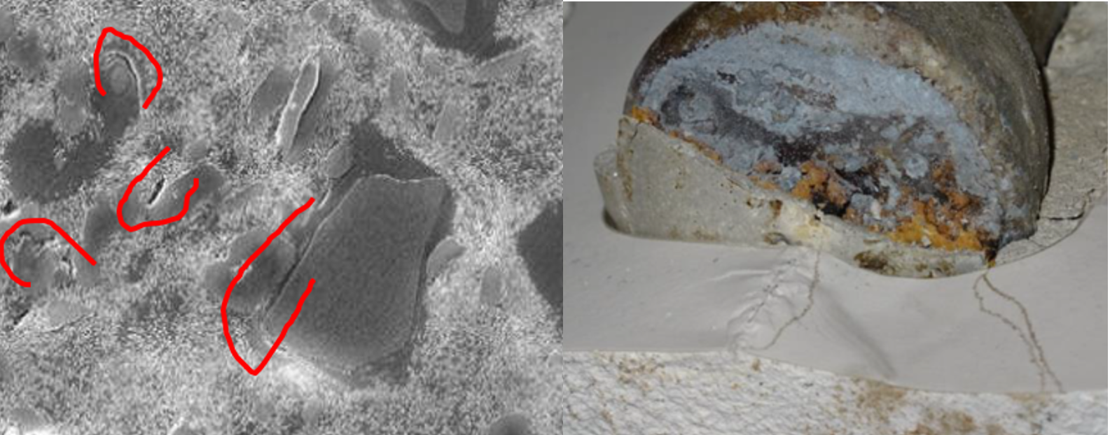
Apart from their end fittings (cap of cast iron and pin of forged steel) porcelain insulators are made of mineral materials. The cement is either alumina cement or more typically Portland cement. The assembly is usually made not with pure cement but with a mortar containing silica (sand) and other minerals. The stability of the cement to temperature change is high and the resilience of such an assembly is driven mostly by the design of the head as well as coupling of the thermal expansion coefficients between the end fittings, cement and porcelain body. Fig. 6 shows the linear expansion coefficients of typical porcelain insulator components. The particularity of the porcelain body is related to its heterogeneous structure, which contains crystals that have their own different properties. This aspect of porcelain leads to inherent ageing of the dielectric, with possible punctures or internal crack propagation (see Fig. 7). This parameter needs to be taken into account when assessing resilience of performance under heat (see Section 2).
Toughened Glass Insulators
Like porcelain insulators, toughened glass insulators are assembled with cement (usually alumina cement but sometimes Portland). However, glass insulators do not have any microstructure. The coupling of the thermal expansion factors is therefore more homogeneous (see Fig. 6). The glass is toughened for strength purposes and pre-stresses built into the bulk thickness of the dielectric are a balance of compressive and extension forces (see Fig. 8).
The mechanical shield represented by the toughening operation renders glass immune to any crack propagation or puncture. A toughened glass insulator will either be intact or will shatter if any excessive adverse stress is applied. In such a case, the glass insulator becomes a so-called “stub” (see Fig. 9) whose electro-mechanical performance remains intact (i.e. no internal puncture and high residual strength). When subjected to heat, the glass can suffer superficial chips or can shatter if exposed to intense and immediate heat. It is important to note that the toughening pre-stress is permanent unless the glass shell is exposed to a permanent temperature of 700°C (1300°F) for a duration of 6 hours or more. But this will never happen since the insulator will shatter at a temperature of approximately 400°F, leaving a stub that remains sound. The next section describes such properties in detail.
Resilience Tests of Insulator Designs Under Heat
1. Polymeric Insulators
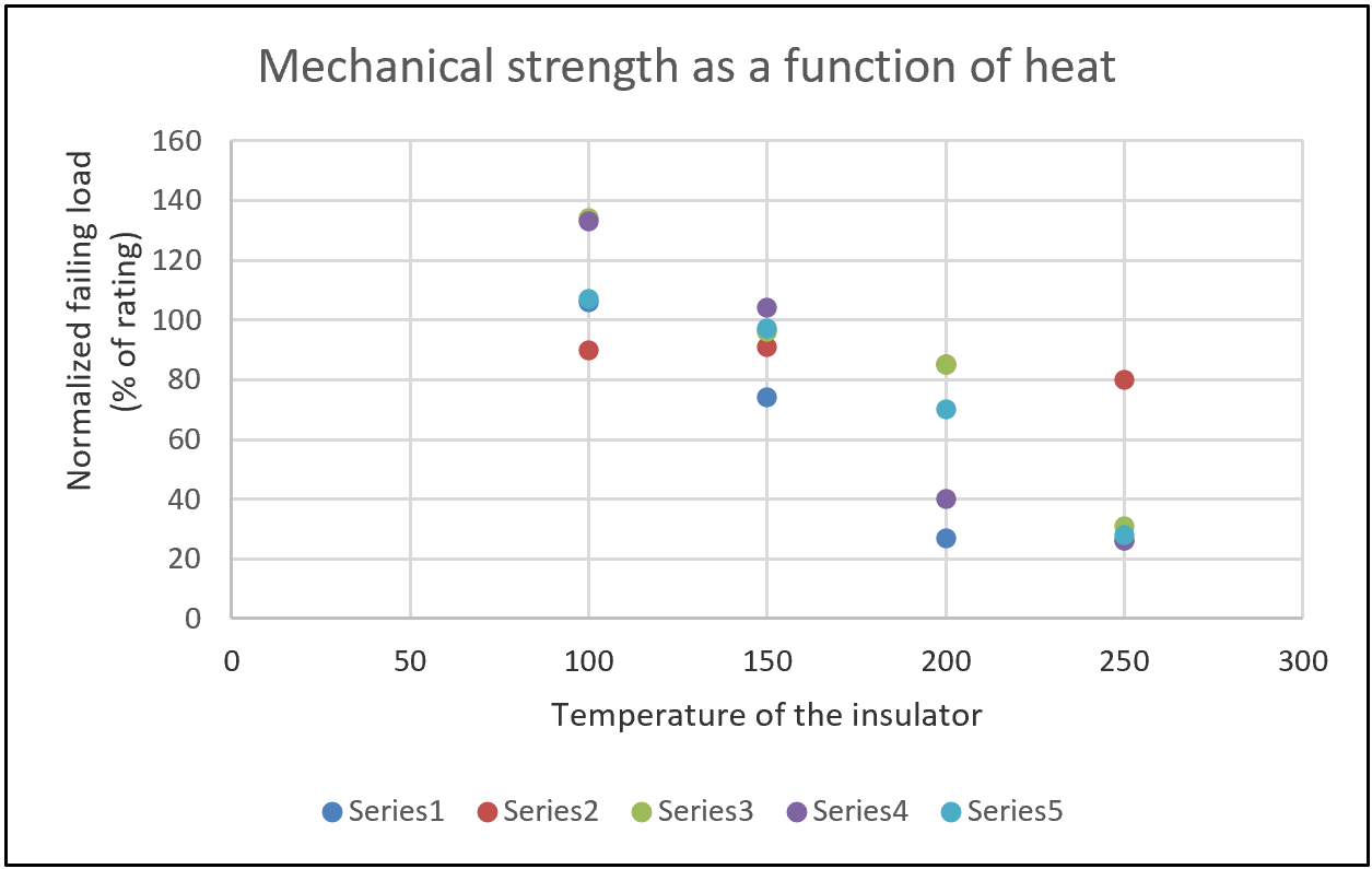
The combination of crimping compression of the end fitting over the fiberglass rod is itself sensitive to heat and as such can represent a weak point under conditions of heat. In order to establish this property, tests were performed with various composite insulators (mostly distribution dead ends). Samples were placed in an oven for 3 hours and pull-tested while still hot until failure. Fig. 10 shows the normalized results with the reference at 100%, corresponding to their ratings. Clearly, strength falls rapidly below the everyday load design of the line.
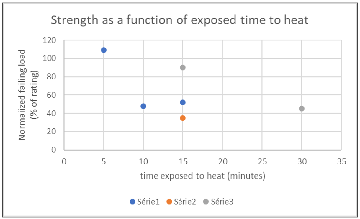
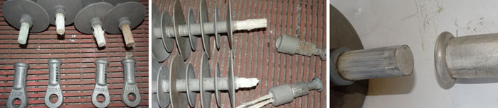
An additional test was performed with insulators exposed for short duration to 300°C (572°F). Fig. 11 shows normalized strength with reference to insulator ratings. It appears that in less than 30 minutes strength goes down from 30% to 40%, with serious risk of line drop whenever such loads are encountered. In most cases, the rod slips outs of the fitting, as shown in Fig. 12. It is noteworthy that the best values (although still weak) are obtained with forged steel fittings and fiberglass rods that have a high Tg (> 180°C/360°F). This test sequence suggests a major risk of line drop with polymers exposed to high temperatures. At some point they will not sustain everyday normal loads.
2. Porcelain Insulators
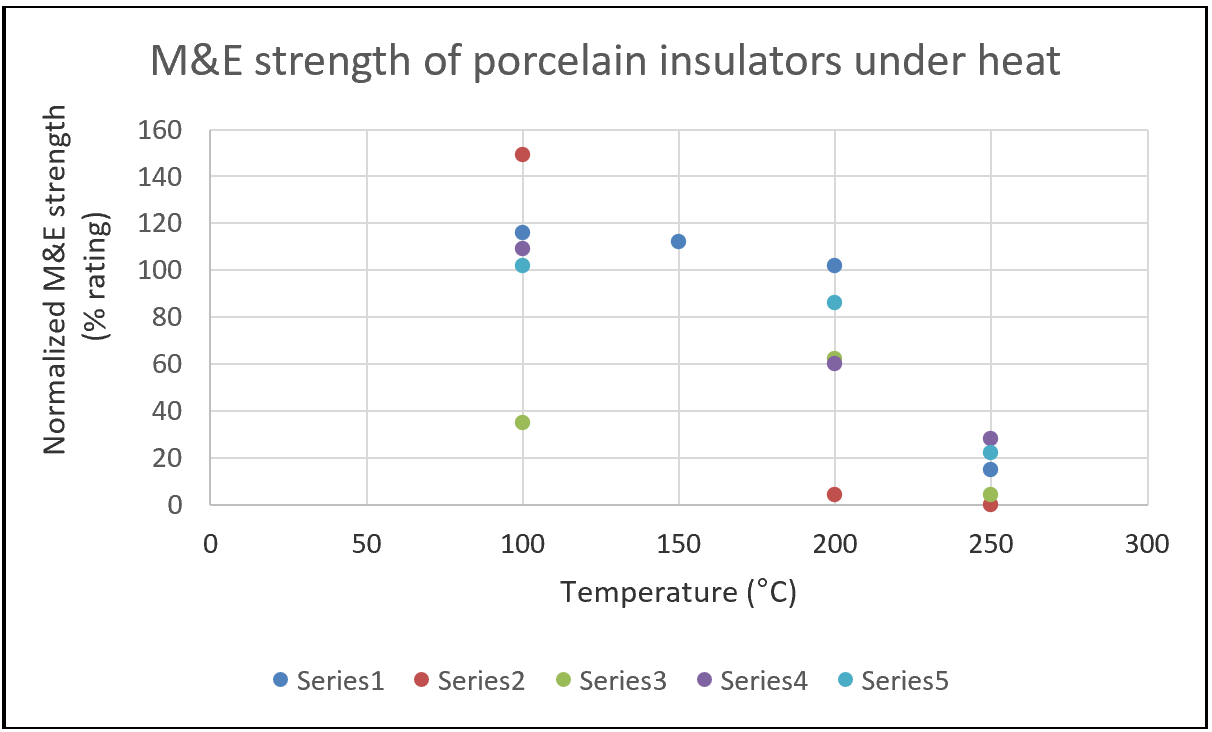
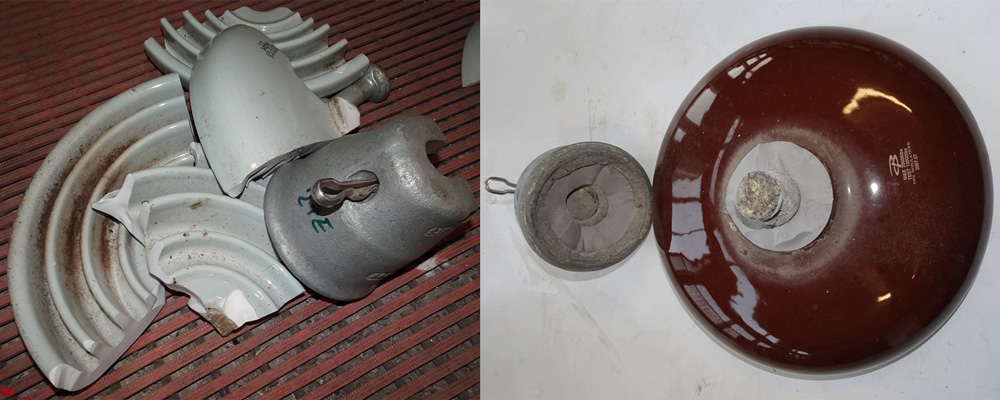
Porcelain insulators underwent a similar test with various units placed in a furnace for 3h before being pull-tested. Given the risk for porcelain to puncture, the relevant test in this case is the ANSI M&E test. A number of units failed with cracks, either visible or not. As expected, the difference in expansion between components favours this type of failure. Moreover, while most units survived the mechanical stress with no separation below the rating, most failed electrically from internal punctures not visible externally. This demonstrated that once porcelain insulators have been directly exposed or in contact with high heat, there is a major risk for having hidden defective units on a power line. Fig. 13 shows the M&E test results and Fig. 14 shows the typical appearance of units after testing.
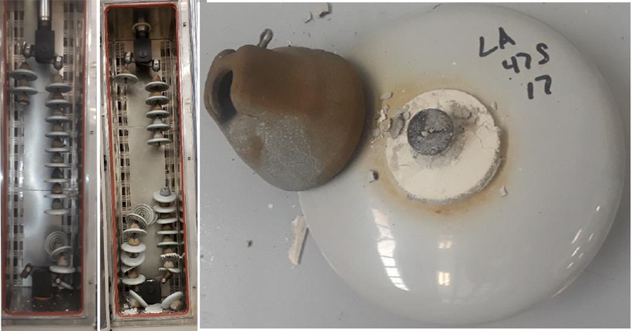
It should be noted that while these results reveal M&E failure only, older porcelain insulators with possible deep existing internal cracks might experience string separation and under such conditions could drop a conductor. Fig. 15 shows such a simulation during a thermo-mechanical test. The cement is itself a mortar and shows no specific heat sensitivity. Still, dehydration of the cement could generate slight crumbling but, by design, the head works under compression leading to a wedge effect. All units tested were assembled with Portland cement. Separation of the head was the result of the porcelain body cracking in two pieces.

3. Toughened Glass Insulators
Toughened glass insulators were tested with the same procedure. The insulators were preheated in an oven for 3h but in this case up to 400°C (752°F) since, as shown in Fig. 16 not much was happening. Toughened glass does not puncture and, as per ANSI, the test is a mechanical test only/ There is no need for a combined M&E test given the fact that toughened glass does not generate cracks but rather shatters. The test was carried out to the maximum temperature of the oven.
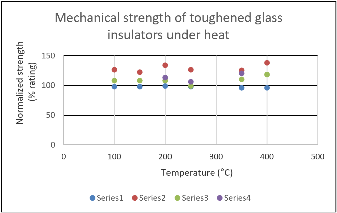
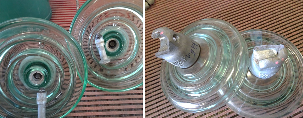
In a few cases the glass shattered before the mechanical separation, but in all the other cases the failure mode was a breakage of one of the fitting, usually the pin as shown in figure 17. It is also interesting to note that, while all the results seem very stable the lowest performer was assembled with Portland cement. Without enough elements to come to any conclusion on the influence of cement, it can be interesting to remember that Alumina cement is a better thermal refractory than Portland.
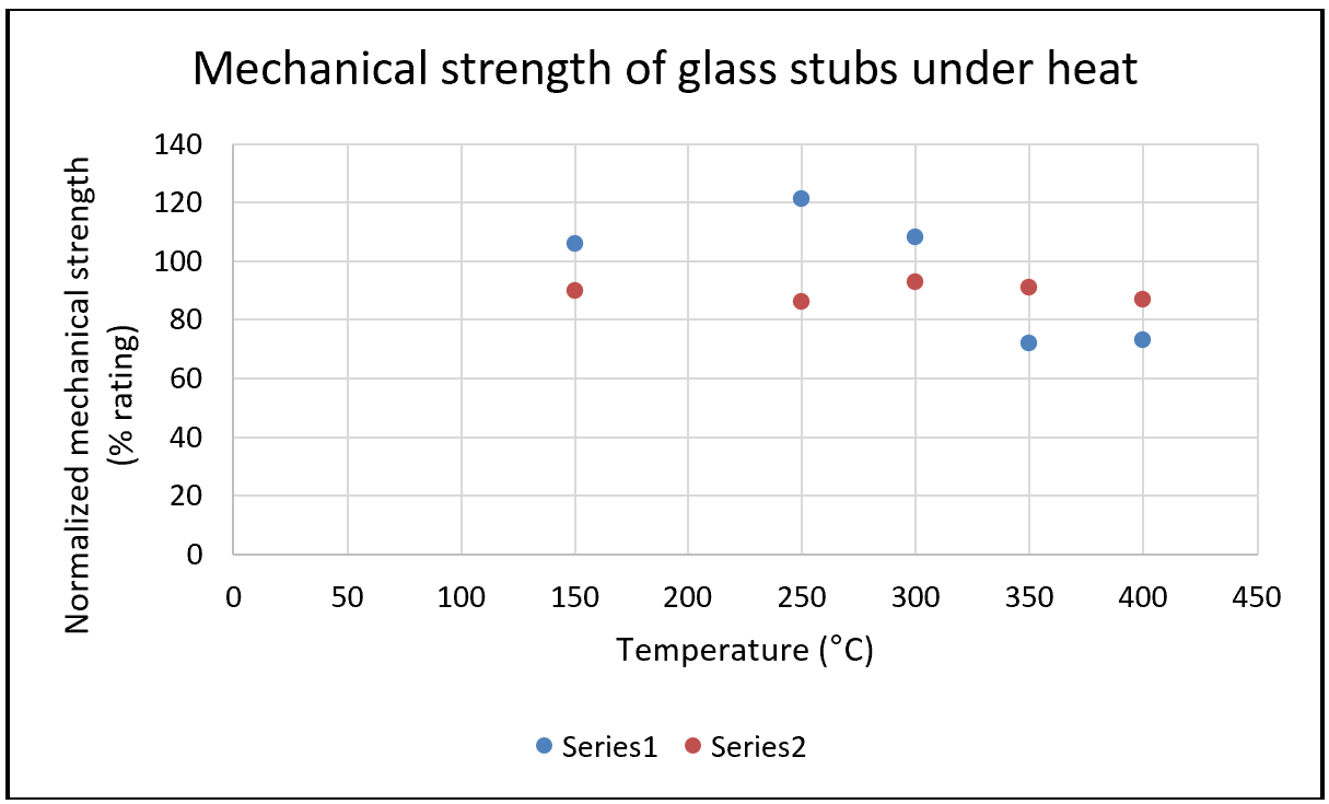
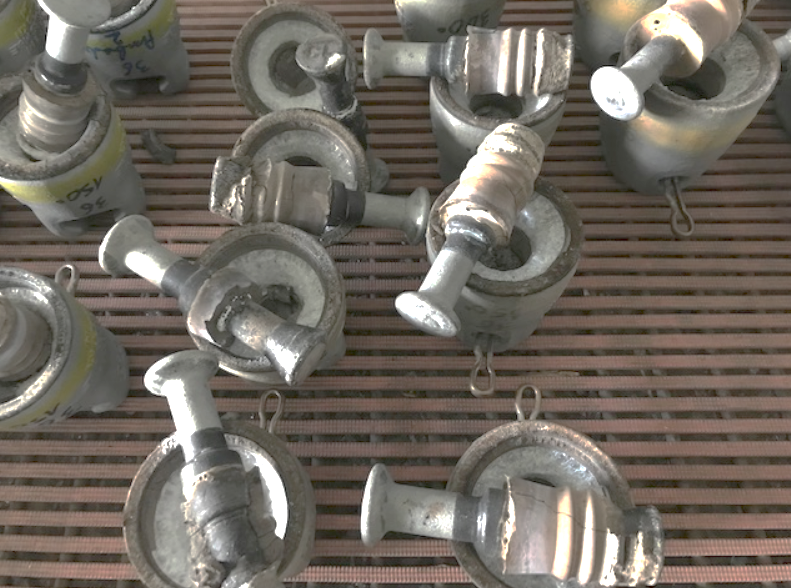
Since toughened glass can shatter, an additional test was carried out on stubs, which were preheated and pull tested. Fig. 18 shows the normalized test results. All failure modes were identical with a pin pull out, i.e. the cement and pin were pulled from inside the insulator head as shown in Fig. 19. All values remained above 65% of their initial rating, which is the requirement in ANSI for new insulators tested for residual strength.
After Wildfire Considerations
The risk factor for a line drop or major accident related to insulator failure during a wildfire has been discussed above. Testing has shown that polymer insulators can snap and drop a conductor whereas this is less likely for porcelain insulators unless they are old. Glass insulators present no such risk, whether intact or shattered (i.e. only stubs).
The next question relates to management of lines from a maintenance perspective once a wildfire is over. Is there a risk to leave some insulators in service that were previously near a fire source and subjected to heat? As shown above, porcelain insulators will not recover from degradation and, if punctured, will remain a potential liability over the future service life of the line. Glass insulators, by contrast, are virtually immune and the only change might be a few shattered units. But this is easy to detect and does not constitute a risk since stubs keep their mechanical strength and are not electrically punctured. Composite insulators are different. Two questions remain:
• What is the mechanical strength of a polymeric insulator that survived the heat event after it cooled off?
• What is the condition of the silicone housing and are there risks to leave these units on the line?
Mechanical Strength of Polymeric Insulators After Cooling
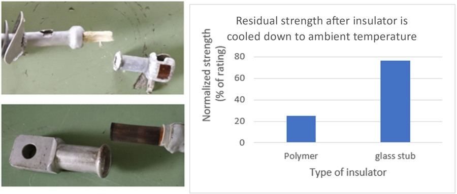
One unresolved issue after investigating behaviour of polymer insulators under wildfire was determining residual strength once these have cooled off. Tests were therefore performed on insulators that had previously been subjected to 300°C (572°F) for 2 h. Fig. 20 shows the results, with strength between 20% and 30% of the rating. This can be compared with the results on shattered glass stubs, which were largely above the standard requirement for residual strength.

Permanent Degradation of Housing & Associated Risks
The chemical mechanism of protection offered by ATH in silicone compounds has been discussed above. The main goal of this chemical in this regard is not to act as a fire retardant, even if it is classified as such. Rather, the main benefit of adding this filler is to slow any erosion of the silicone during dry band arcing or pollution related activity.
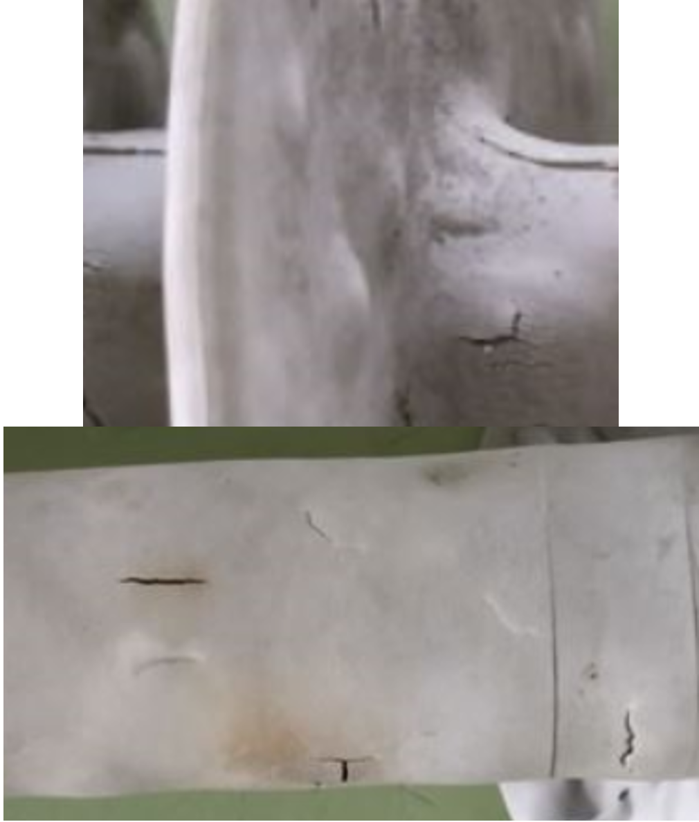
At some point, the rubber will fail leading to cracks on the shank. The rubber itself does not burn and, as most compounds used in the power supply industry are classified in IEC 60695 as HB and V0. However, once cracks appear, the insulator is likely to fail electrically (i.e. by internal tracking) or mechanically (by brittle fracture or decay fracture). It is important to also consider the presence of sulphuric acid and other fire related acids that could progressively degrade the insulator core. In most cases these types of degradation are difficult to detect visually, as shown in the examples in Fig. 21.

Conclusions
The findings of this research point out typical weaknesses and strengths of different insulator designs:
• Mechanical strength of composite insulators drops quickly under excessive heat, leading to risk of line drop or at least a significant reduction in strength once a wildfire event is over.
• Degradation of the housing of composite insulators under heat and fire can breach the integrity of the housing and lead to moisture and acid ingress. Future failures and line drops after the fire is out could still occur if these small cracks are not detected and the insulators not replaced.
• Porcelain insulators would not drop a conductor during wildfire unless they are old and have an aged microstructure. However, the large gap between the thermal expansion factors of the components of porcelain insulators can lead to punctures or internal cracks that are not apparent from visual inspection alone.
• Toughened glass insulators do not exhibit loss of performance and, if a thermal shock shatters the glass, the stub remains mechanically safe even at high temperature. Visual inspection is simple after a wildfire and there is no need for urgent replacement.