Among the challenges when it comes to insulator design for UHV applications is to fulfil required lengths while also mitigating resulting negative effects on insulation and mechanical performance. Efforts can be made in system design to reduce levels of switching overvoltages. Similarly, creepage distances can be decreased through selection of insulators with a hydrophobic surface. Indoor solutions can also help by providing the conditions to reduce required arcing distance and improving electrode design.
This edited past contribution to INMR by Dong Wu, now retired from ABB HVDC, reviewed impact of insulator design on system parameters. Design issues and solutions related to external and internal insulation design of insulators for UHV applications were also discussed with emphasis on post insulators made of composite hollow core insulators.
Insulators are key components of power systems and are offered today in a range of different materials and production methods, including porcelain insulators with hydrophobic RTV silicone coatings, hybrid insulators and composite hollow core insulators with different solutions for the internal insulation. It is important to know the relative strengths and weaknesses of these alternatives in order to make an optimal selection for the application. Design of insulators should accommodate system requirements that include voltage and current levels, ambient conditions, layout and required mechanical strength. Combinations of these parameters result in large variety in application situations. While efforts have been made by industry to standardize design of insulators, optimizing system design makes it necessary to make adjustments in their design or to make an entirely new design. This is especially the case for systems with unconventional requirements such as an Ultra High Voltage (UHV) system.

UHV System Requirements on Insulators
Voltage Levels
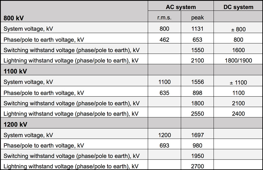
Typical voltage levels for UHV are listed in Table 1. For AC systems, voltage levels are found in the IEC standard. For DC systems, voltage levels are those found in project technical specifications. For easy comparison, both peak and effective (r.m.s.) levels are given for AC voltage.
For insulators, the dimensioning parameter in most of cases is one of the following:
• Creepage distance, determined by pollution performance under the effective level of phase/pole to earth operation voltage;
• Arcing distance, determined by the SIWV (switching impulse withstand voltage).

For corona free design of terminations, peak operating voltage should be used. In some cases LI (lightning impulse) can become the dimensioning variable for internal insulation of certain apparatus. As listed in Table 1, UHV DC systems face more stringent task than UHV AC systems when it comes to dimensioning parameters.
Dimensioning Parameters
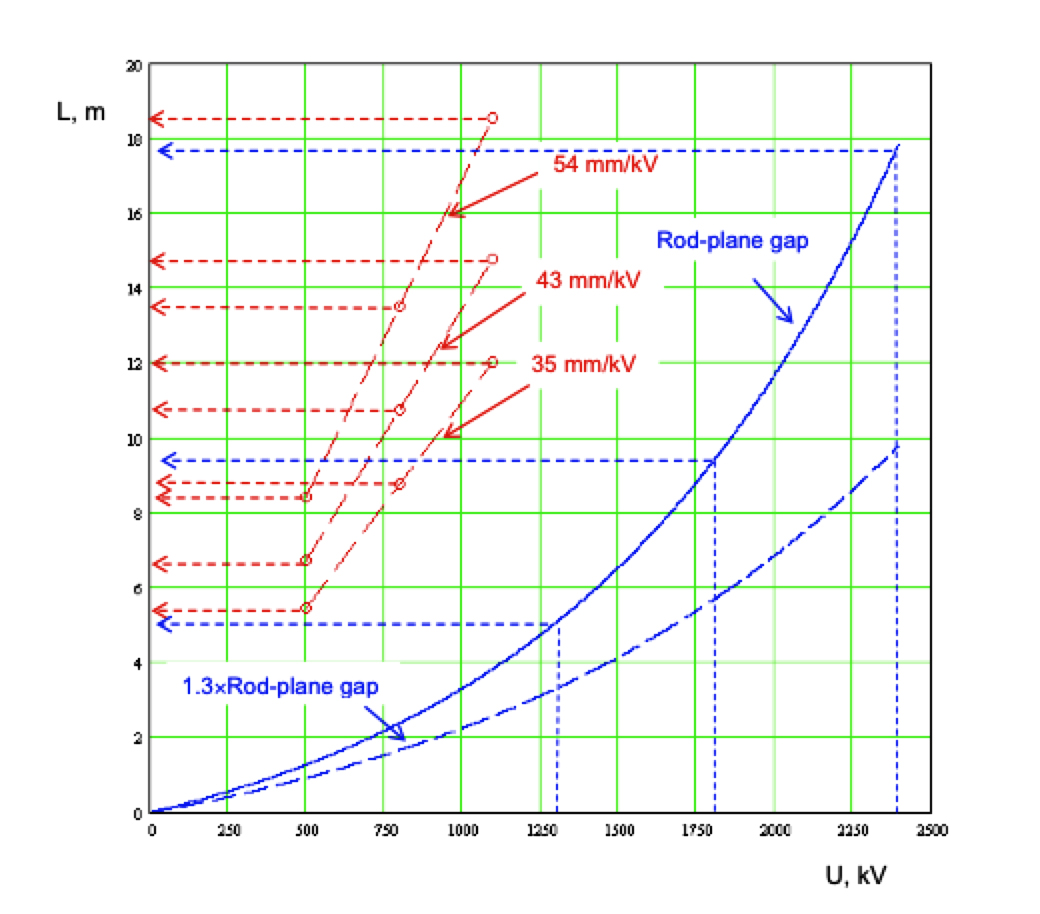
Insulator lengths determined by creepage distances or by arcing distances are compared in Fig. 1. The relationship between operating voltage and insulator length deduced from creepage requirement are plotted in the red dashed lines. For three required USCD (unified specific creepage distance) values: 35, 43 and 54 mm/kV, required insulator lengths have been calculated for DC pole to ground voltage of 500, 800, and 1100 kV, with a CF (creepage factor) value of 3.2. As example, one can find that: 43 ´ 800/3.2 = 10.8 m.
The relationship between SI voltages and insulator lengths are plotted in blue lines. Here the rod-plane relationship is used and based on the formula:
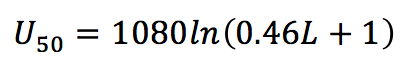 The levels of SIWV required by 500, 800, and 1100 kV DC systems have been converted into 50% breakdown voltage, U50, with two sigmas of 6%. Corresponding U50 levels have been rounded up to 1300, 1800 and 2390 kV. The corresponding insulator lengths (arcing distances) can therefore be estimated, as marked in blue dash-arrows. Many parameters that can alter the values given in Fig. 1. For insulator lengths obtained through creepage, final values will be influenced by insulator surface material, CF value, and diameter. A more decisive parameter will be the level of SPS (site pollution severity). For lengths obtained through arcing distances, this will be influenced by the gap factor resulting from installation structures. Nevertheless, for UHV applications insulator length will in most cases be longer than 10 meters.

Indoor or Outdoor DC Yard
To mitigate difficulties in design of insulators for UHVDC applications, there have been intensive discussions on whether or not DC yards should be built indoors. No such discussions have been reported for UHV AC applications, partly due to availability of gas insulated substations for AC. Pollution problems under DC voltage are also well known. Under UHV DC, parameters such as insulator length, mechanical strength, insulator diameter and pollution performance could form a ‘run-away’ loop. Therefore, building an indoor DC yard becomes one attractive alternative. Another situation to be considered is the saturated relationship between arcing distance and switching impulse when it comes to UHV levels. For 1100 kV UHV DC, for example, arcing distance of an insulator may need to be as long as some 18 m to ensure a U50 of 2390 kV under switching impulse. At the same time, required length due to creepage could be shorter than 18 meters. SIWV may then become the dimensioning parameter. For indoor conditions, arcing distance can be reduced by creating a larger gap factor than that of a rod-plane gap through improved structure of electrodes. For outdoor conditions, however, pollution and rain eliminate the screen effects of large electrodes. Higher gap factors than that of a rod-plane gap may therefore become difficult to achieve. Moreover, for indoor DC yards there is no need for stringent humidity control. Without natural precipitation, wetting of pollution by condensation and absorption is a relatively slow and mild process. As such, stress on the insulator is less severe than under natural precipitation. Even in the unlikely situation that pollution level inside an indoor DC yard reaches the so-called ‘very heavy’ level, research has demonstrated that a porcelain insulator with a USCD in the range of 30 to 40 mm/kV can withstand such severity. Without need for humidity control, an indoor design becomes economically more attractive.
Insulator Design for UHV
External Insulation
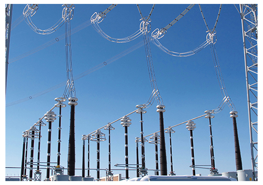
For outdoor applications, characteristics of surface material, shed profile, diameter and required USCD in relation to SPS have been discussed in the literature, including in several CIGRE and IEC technical guidelines. For UHV applications at outdoor conditions, challenges come mainly from how to mitigate negative effects of long insulators with large diameters during bad weather such as fog, rain or snow. This is especially the case for insulators installed vertically or with a small angle from vertical. Under UHV, it becomes difficult to simulate in a laboratory the effects of water accumulation, distribution and cascading along an insulator of more than 10 m length. There is simply not yet enough data that could provide an exact account of those effects on breakdown voltage. In some cases, insulators of multiple-columns have been used and this can also lead to design uncertainties. Other factors that further complicate the situation are effects of metallic flanges as well as height and shape of steel pedestals. Such a complex situation could be visualized at the 800 kV UHV DC outdoor DC yard in Fig. 2. Here, all insulators under 800 kV DC pole voltage are of some 11 m in length. It can also be imagined what challenges would be encountered if an 1100 kV UHV DC yard with insulators of about 18 m length will be built.
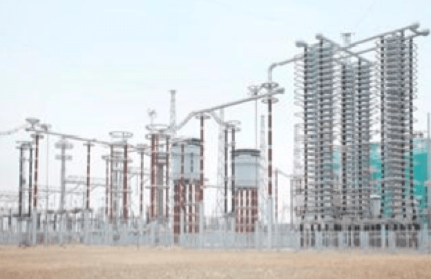
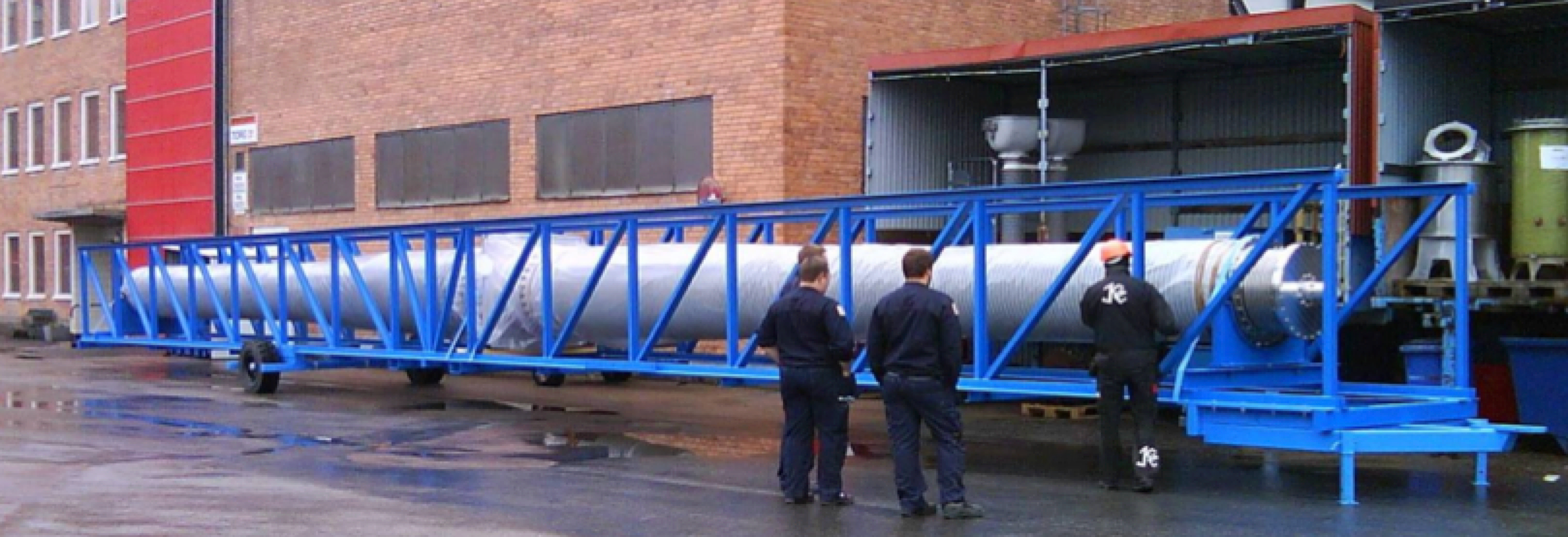
For UHV applications, one issue has been to manufacture porcelain post insulators with large core diameters. Post insulators made of composite materials have therefore emerged as an alternative. One of the benefits is use of HTM (hydrophobicity transfer material) surface with improved external insulation strength. But a downside is emergence of internal insulation issues. For example, comparison made more than 10 years ago resulted in a decision that all post insulators in the DC yard in Fig. 2 would be porcelain coated with RTV silicone. By relying on the hydrophobic property of the coating, required USCD was reduced by 20%. Insulators that otherwise would be of some 14 m long became 11 m. As a result, core diameter was also reduced somewhat, resulting in lower quality risk during production. It is worth noting that the smoothing reactors in this station weigh more than 60 tons each. Consequences of mechanical failure overwhelm consequence of any possible external insulation flashover.
Internal Insulation
For apparatus such as bushings, internal insulation design is another technical area and not discussed here. Still, internal insulation design has an impact on external insulation through electric field grading. For vertically installed apparatus with internal axial voltage grading, interactions between internal voltage distribution external voltage distribution require special attention. For example, differences between internal and external voltage distribution can lead to failure/puncture of hollow core insulators. For cap & pin line insulators and porcelain post insulators, there are few internal insulation issues. Failures of glass or porcelain insulators are typically due to inferior material or production quality. However, for long-rod composite insulators, internal insulation issues are a consideration and it is well known that moisture ingress along material interfaces and inside the rod can cause insulation problems and failure.
CLICK TO ENLARGE
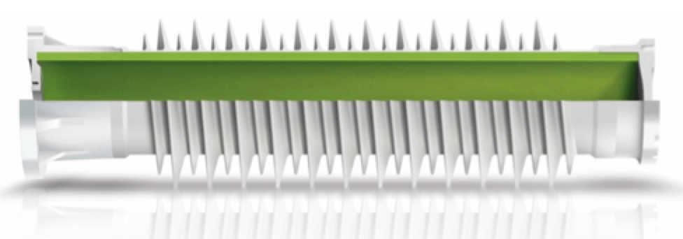
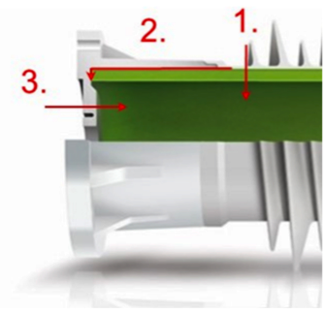
Fig. 3 shows a composite hollow-core post insulator. The main challenges for this type of insulator are to determine the most suitable materials to be used for internal insulation as well as methods to prevent leakage and/or moisture ingress. Potential leakage paths are marked in Fig. 4
Several materials have been used as internal insulation:
1. Solid epoxy rod;
2. Polyurethane (PUR) foam;
3. PVC foam;
4. Pressurized gas;
5. Low-pressure (near atmosphere) gas.
There is also the hybrid type post insulator with porcelain core and silicone rubber sheds. In general, the weakest point of internal insulation is at interfaces. For internal insulation with materials 1-3 as above, a relatively rigid interface is introduced between core and tube of the hollow core insulator. This interface can suffer from risk of moisture ingress even during manufacturing. There are also risks under operating conditions, e.g. when subject to mechanical stress, peel stress will increase at the interface. Foams are better under such conditions than a solid rod, since they are softer and better follow with movement of the tube. No method is available to monitor such risk after assembly.
Insulators filled with pressurized gas are not a new technology. In the case of apparatus with hollow core insulators, for example, pressurized gases have been widely used at all voltage levels to increase strength of internal insulation for various types of apparatus. Fig. 5 shows a UHV DC 1100 kV wall bushing insulated with pressurized gas. For such applications, gas leakage will result in reduction in internal insulation strength. Therefore, gas pressure needs to be monitored. While a small gas bushing can be installed and used, if necessary, to fill up gas during maintenance, such a gas bushing can itself become the weak point for leakage.
For station post insulators filled with gas, it is not necessary to have pressurized gas since arcing distance inside and outside is of similar length. While external insulation may be stressed by various ambient conditions, internal insulation is under a well-controlled condition. Therefore, having gas pressure close to ambient will be sufficient for the purpose of insulation. With smaller pressure difference between inside and outside of the insulator, risk of leakage is reduced. Furthermore, the potential leakage paths 2 and 3 as in Fig. 4 should be made secure by redundant sealing solutions and accurate tightness testing. Since the strength of internal insulation does not rely on higher gas pressure, there is no need to monitor and refill nor is a gas bushing needed to eliminate this weak point.

Conclusions
For UHV applications, the main challenge when it comes to insulator design is to fulfill required length while mitigating the resulting negative effects on insulation and mechanical performance. Efforts can be made in system design by reducing SIWV levels. Required USCD could also be reduced through use of insulators with an HTM surface. An indoor solution can provide the conditions to reduce required arcing distance by improvements in electrode design. On the other hand, insulators with different type of materials and production techniques have been developed and are available. It is important to know the strength and weakness of these insulators in order to make the best possible selection.