Several years ago, utilities in Southeast Asia embarked on a bushing reliability survey and, based on findings, formulated mitigation measures to improve bushing performance. This edited 2017 contribution to INMR by S. Gobi Kannan, Chitapon Jedwanna and Henny Ika, respectively at Tenaga Nasional Berhad (TNB) in Malaysia, the Electricity Generating Authority of Thailand (EGAT) and Perusahaan Listrik Negara (PLN) in Indonesia, reviewed experience with bushing failure for the purpose of learning what measures can help reduce such risk.

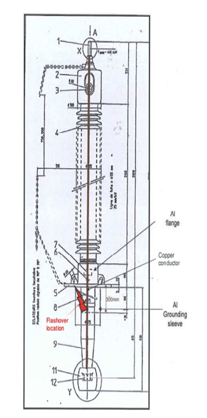
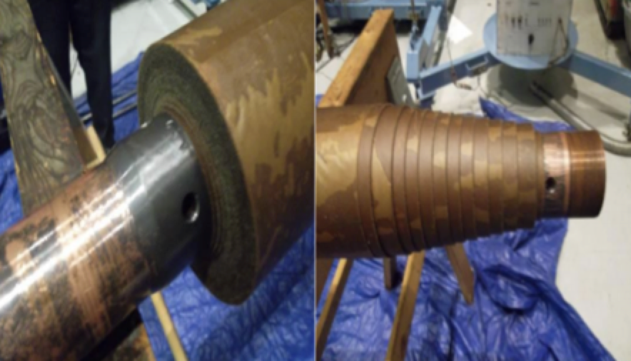
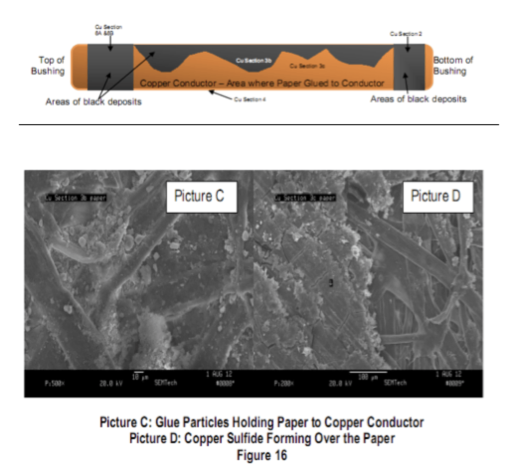
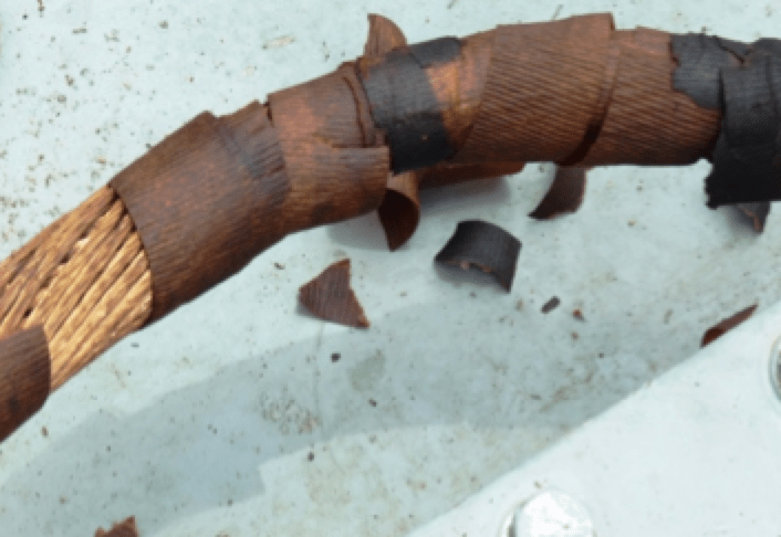
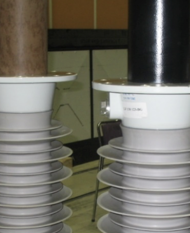
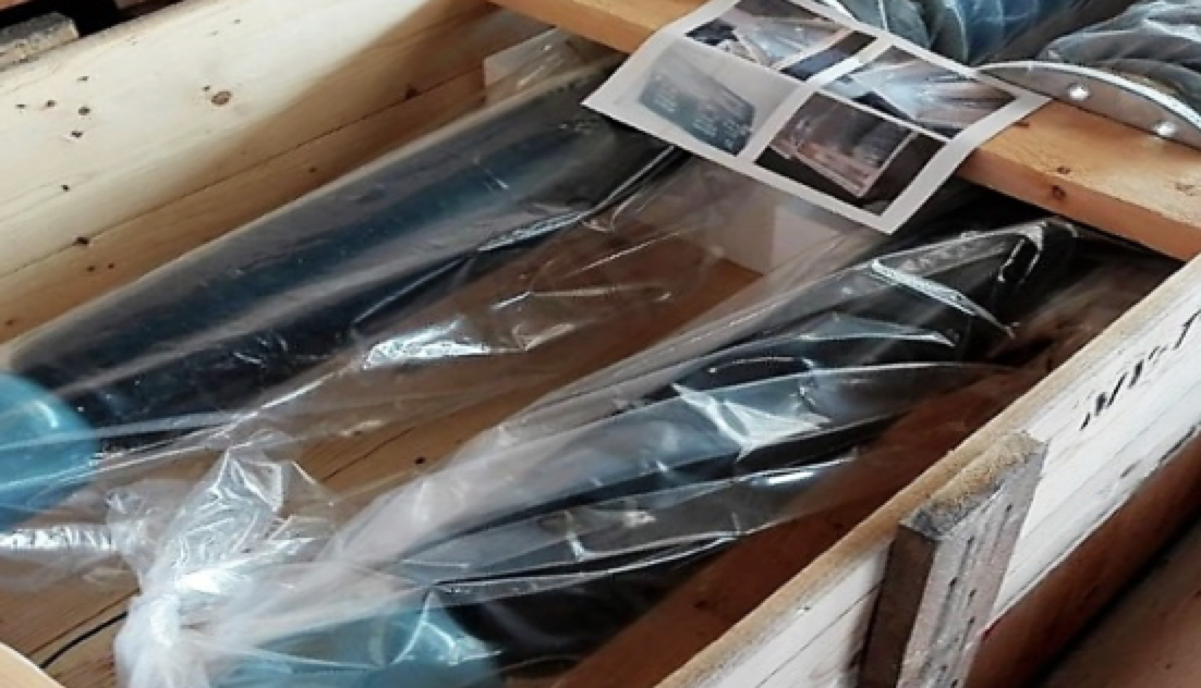
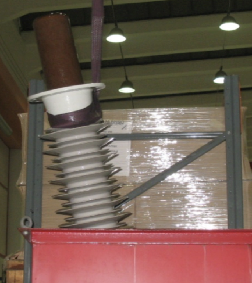
Case #1: Copper Migration on 300 kV Bushing Manufactured in 1996 (ref. Figs 1 to 4)
Root Cause: Site and laboratory examination, together with historical failure records, suggest that the dielectric insulation breakdown in this case was due to one or more of the following:
• Poor stress control design resulting in high electrical stress at certain locations along the paper/foil insulation;
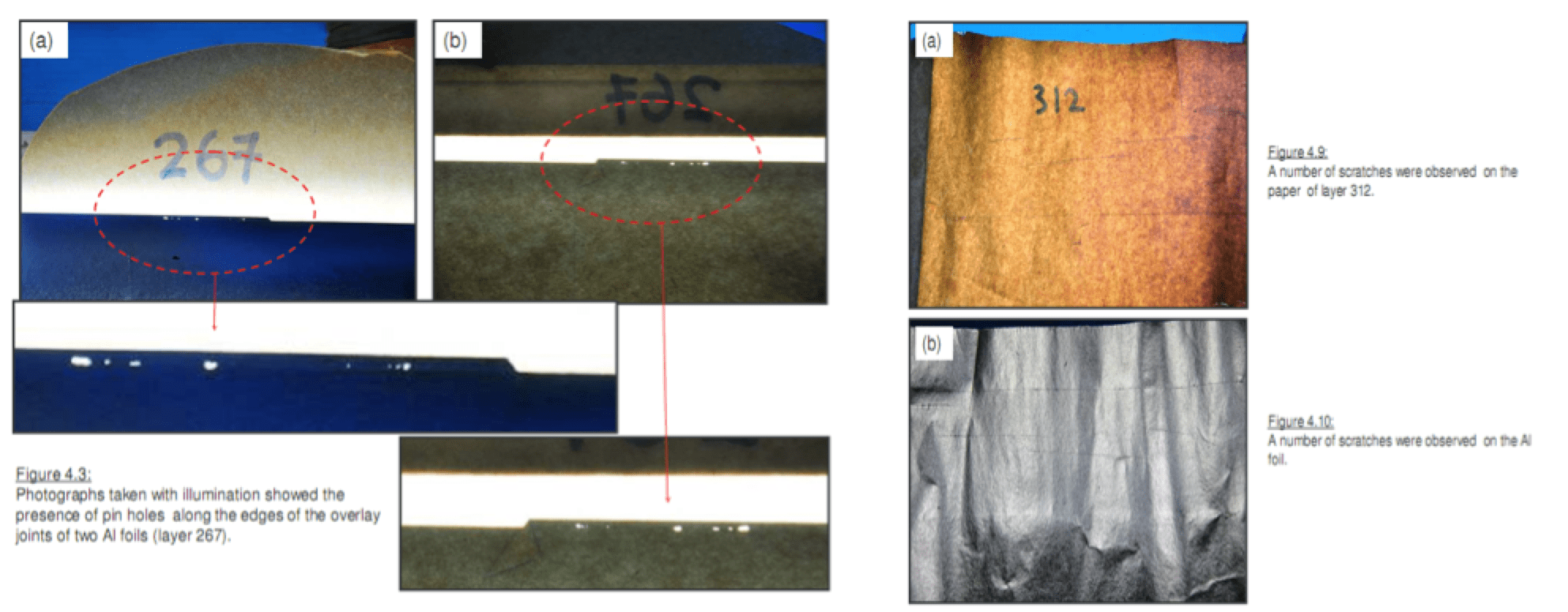
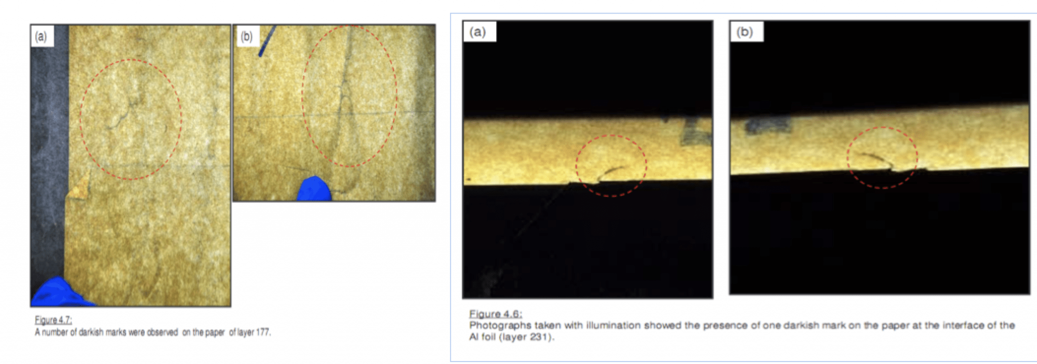
• Poor manufacturing quality as seen in laboratory examination of some paper/foil insulation layers leading to uneven distribution of electrical stresses;
• Development of electrical treeing along the insulation as a result of copper migration, made worse by the high electrical stresses.
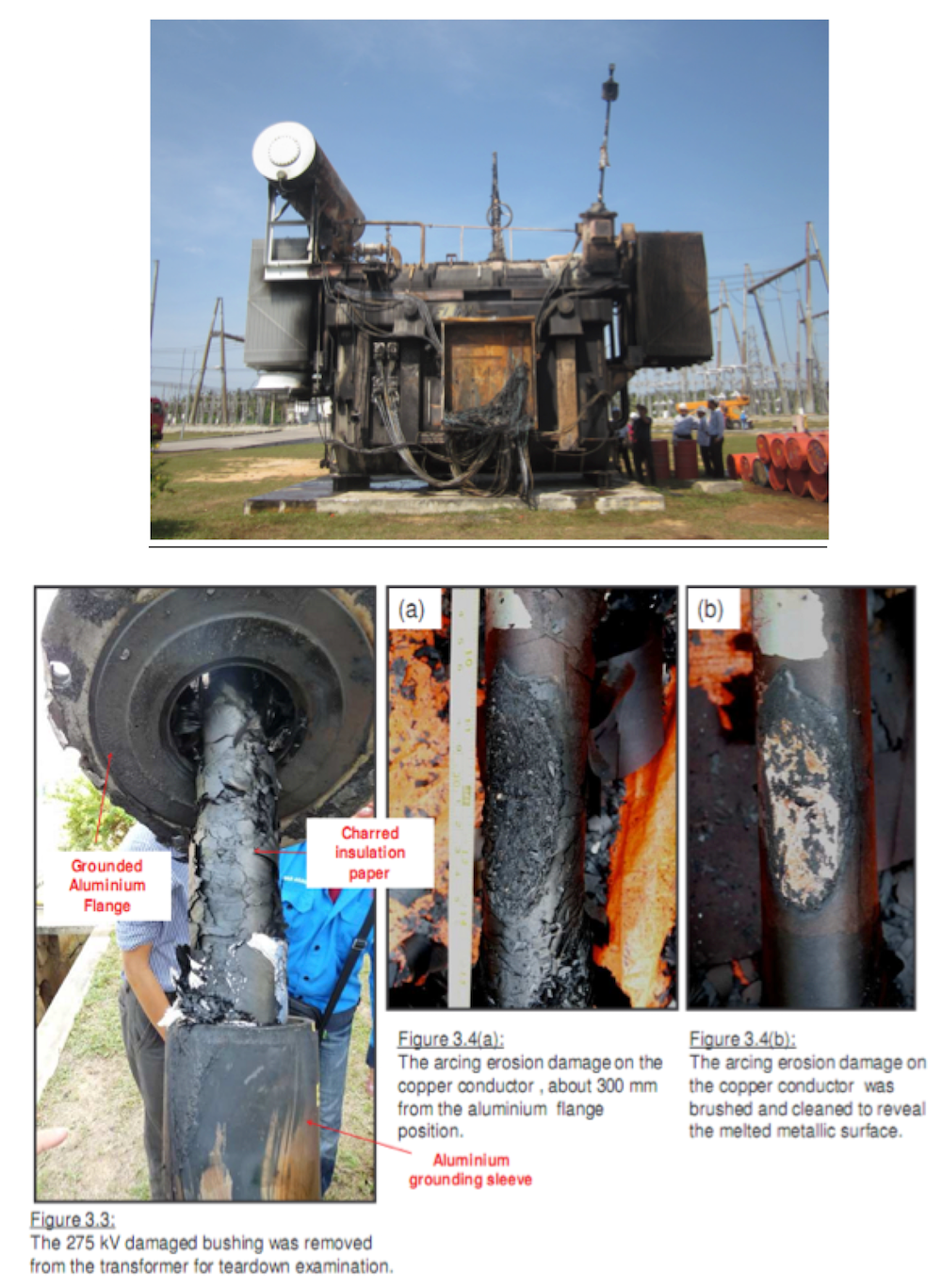
(Source: DOBLE Proceedings 80th International Conference 2013)

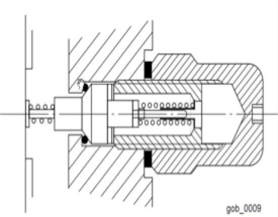
Case #2: Test Tap Problems (Figs. 5 to 9)
Surveys among ASEAN utilities indicate that about 10% of bushing failures relate to test tap problems. In this particular instance, it was found that the test tap measurement and tap bushing had no continuity. Insulation resistance measurements indicated an open circuit and disassembly of the test tap revealed:
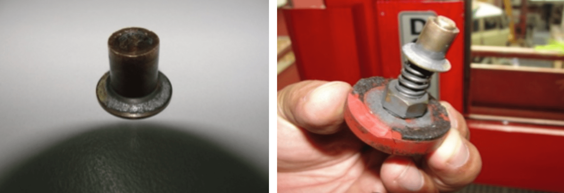
• Utility experience in the region shows that the majority of test tap failures have been attributed to the spring-loaded design versus the permanent connection type (see Figs. 8 and 9). Poor spring contact pressure over the years and possible damage during high surge current flow was determined as possible root cause of the failure mode that resulted in floating potential and arcing at the last layer of the condenser design bushings. This could lead to contamination of the insulating oil at the bottom side of the bushing and eventually dielectric failure breakdown.

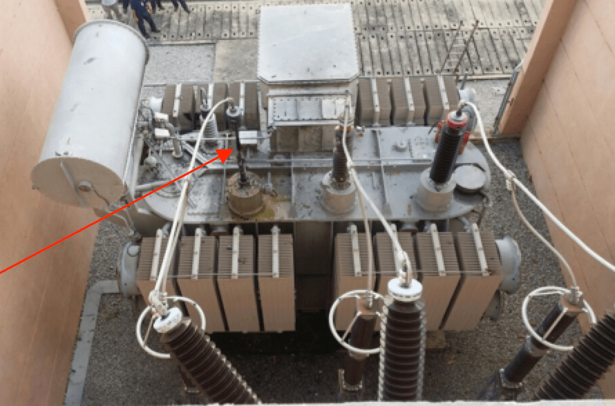
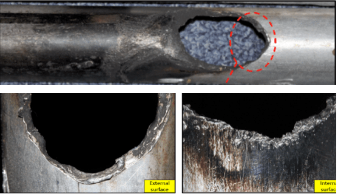
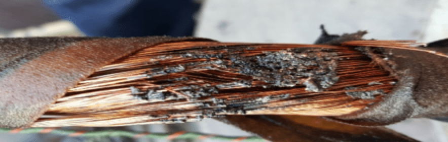
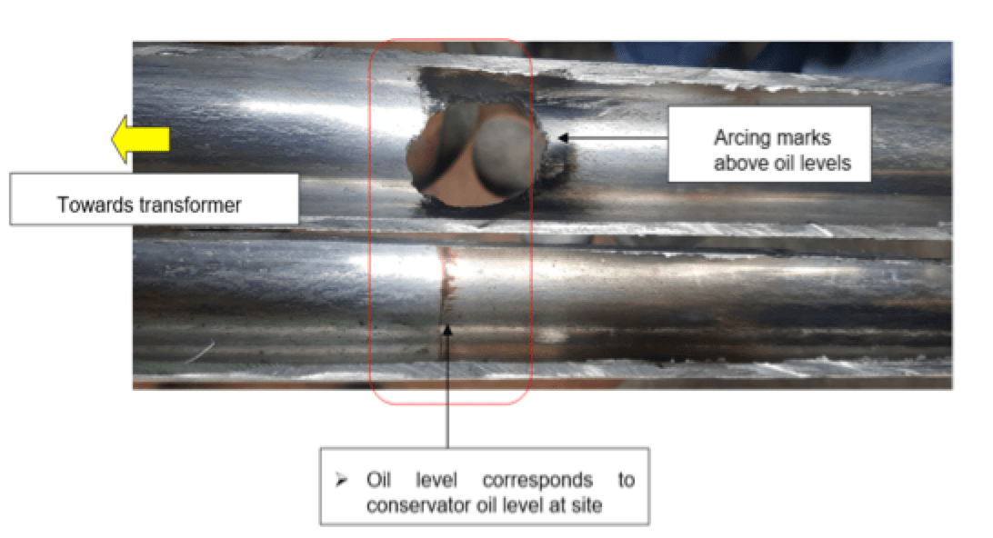
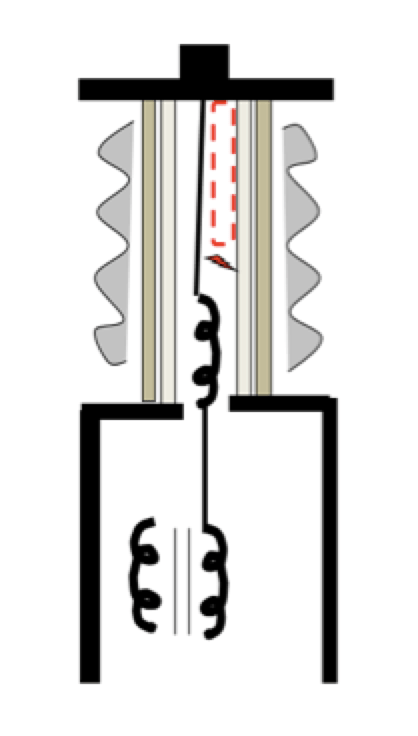
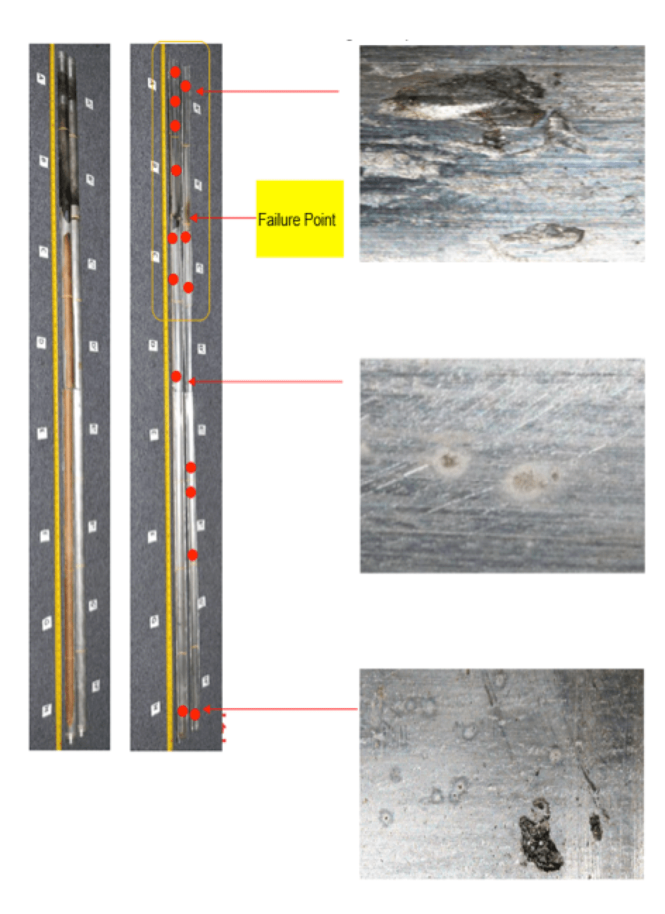
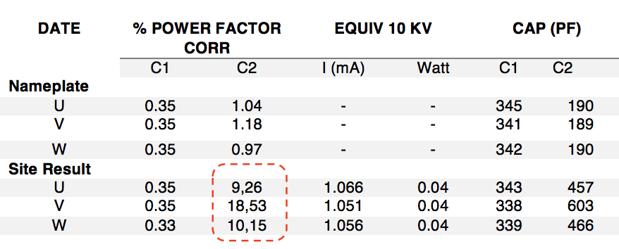
Case #3: Draw Lead Bushing Fast Transient Issue in GIS/RCT Substation
Root Cause: Loss of insulation dielectric strength of main condenser due to heat generated along the bushing’s aluminium tube as a result of fast and very fast transient phenomena in the system during switching.
Measurement of Power Factor and Capacitance on the bushing prior to failure did not reveal any abnormalities (see Table 1).
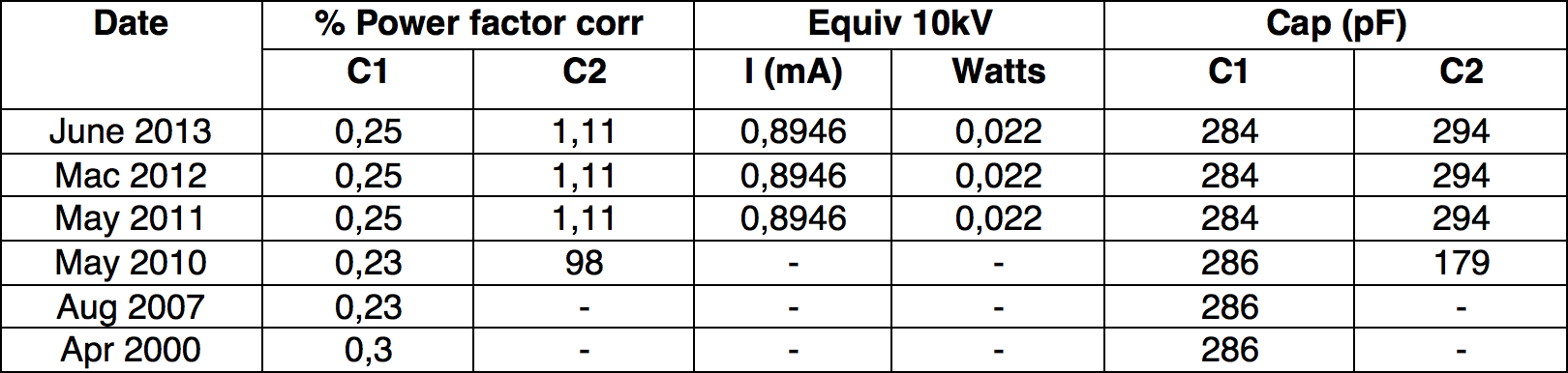
The phenomenon of fast transient on a bushing’s draw lead is still not fully understood in the field. Evidence of arcing/sparking between draw lead and aluminium tube at common potential raises concerns, especially in regard to risk of failures at reactive compensator or in GIS substation installations. As improvement, the specification for bushings with a draw lead connection has been revised. The transformer manufacturer must now ensure the draw lead cable within the tube is insulated using thermally upgraded insulation material with minimal thickness of 1mm. The goal is to avoid causing any significant rise in hot spot temperature of the bushing and thereby prevent any arcing between draw lead and aluminium tubing during all fast transient phenomena in the system.
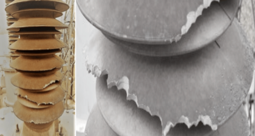
Case #4: Monkey Damage to Polymeric Insulators (Still Unresolved)
To reduce risks from explosion and pollution, some utilities have started to use bushings with polymeric insulator housings. Recently, some of these bushings have been attacked by monkeys that chewed on the insulators. Discussions with suppliers on use repellents or other inhibitors have been in progress but without a commercial solution in the case of transformer bushings. Some severely damaged sheds have required urgent replacement to prevent external flashes and risk of ingress into the main condenser layers. Nonetheless, no utility members reported any flashovers since affected bushings were immediately replaced once identified during routine substation inspections.
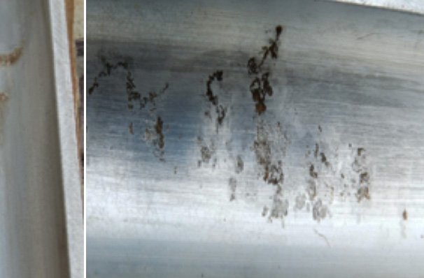
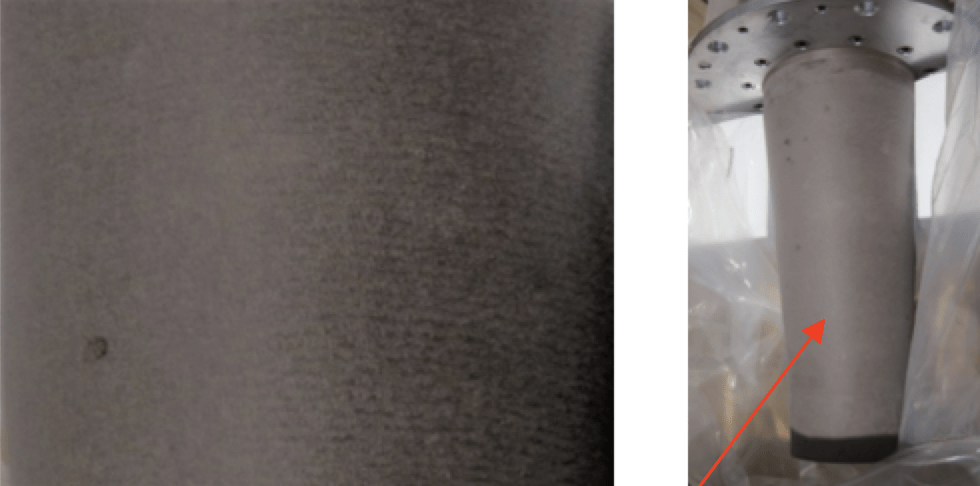
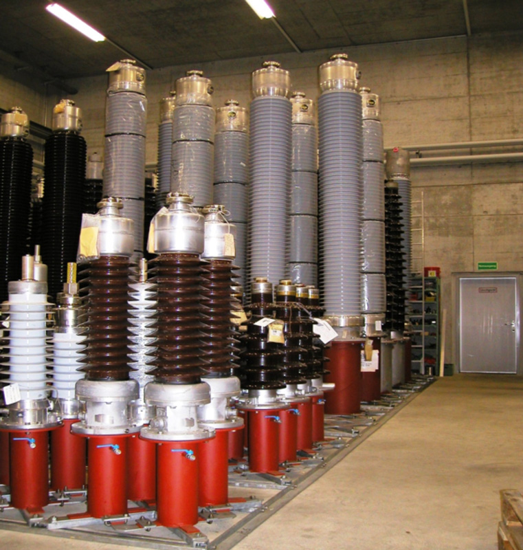
Case #5: Hygroscopic Issues for Resin Impregnated Paper Bushings
Hygroscopic properties of resin impregnated paper (RIP) bushings need to be addressed in the event of exposure to high humidity during storage or handling. Prolonged exposure under environments with high humidity can lead to the bottom of these bushings absorbing moisture that can impact performance. Change in colour at the bottom of RIP bushings is indicative of this issue, which is a major concern for utilities operating in high humidity environments.
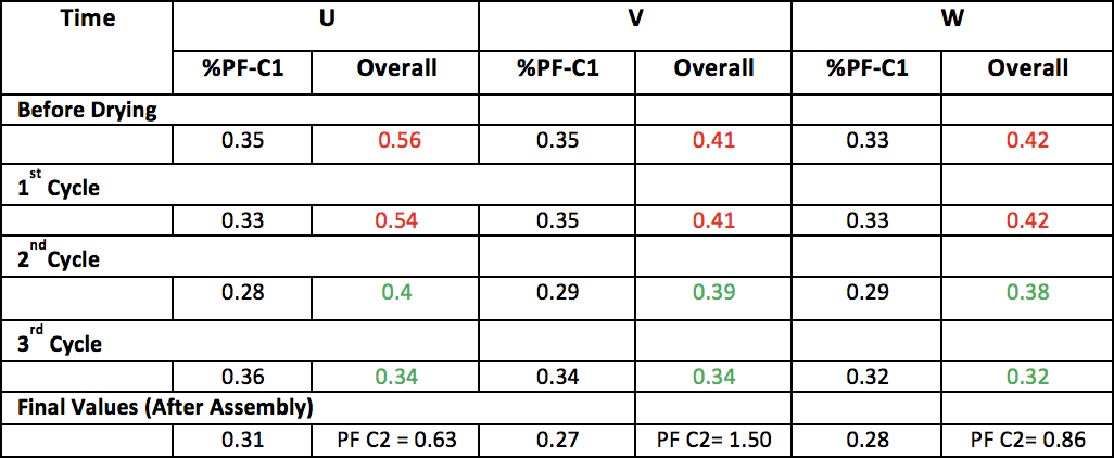
• While measurements show no significant change in C1 parameters, Table 2 illustrates changes in pF C2 (after assembly) values that are sensitive to humidity ingress at the bottom of a bushing’s surface/core.
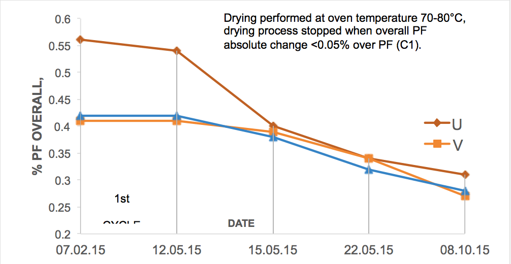
For those RIP bushings with high humidity, drying in an oven has been found to be effective in removing moisture from bottom surfaces. Data from one case study (see Fig. 18 and Table 3) highlighted such issues, usually detectable by high pf C2 values after assembly. Typical values of 2-3% are acceptable limits recommended by OEMs. PF for the overall bushing (HV terminal to flange) is typically near to C1 values for dry bushings and this is a useful parameter to monitor during any drying process since PF C2 measurement may not be accurate when a bushing is tested by itself, before being mounted.

Initiatives in Mitigating Bushing Failure Risk
While the risk of transformer fire due to bushing failure is relatively low, it is not negligible. Implementing strategies to prevent injuries, minimize impact on adjacent assets and avoid loss of supply is therefore an essential part of management of transformer assets. The aim of these strategies and initiatives is to address and quantify risk of fires and provide guidance on how this risk can be managed in a safe and cost effective manner.
The following risk mitigation measures are based on discussion and best practices among utility members and have been deemed effective at improving performance of bushings in power grids:
1. RIP bushings are preferred over OIP for condenser bushing classes 52 kV and above;
2. Procurement only from suppliers with proven designs. Product pre-qualification process is recommended;
3. Oil-filling and sampling is NOT recommended for OIP style bushings, unless performed by competent personnel or under OEM supervision:
4. Enhanced maintenance practices should include:
• Replacing and/or monitoring bushings that exceed acceptable criteria;
• Relying on power factor and capacitance measurements deemed sensitive in detecting incipient problems;
• Conducting thermal scans at least once every 6 months;
• Carrying out visual inspection at least bi-monthly, checking for leakage or severe external contaminants.
5. Storage and handling for RIP and OIP bushings should follow OEM recommendations. For example, Fig. 19 shows typical storage practice for periods exceeding 12 months using specially designed metallic covers filled with dry transformer oil.
6. Use of RIP protection coating as a moisture barrier has been under evaluation for effectiveness in the field.
protective coating.
Fig. 22 illustrates a moisture ingress test comparing a standard bushing and one with special coating, as currently used by some member utilities.
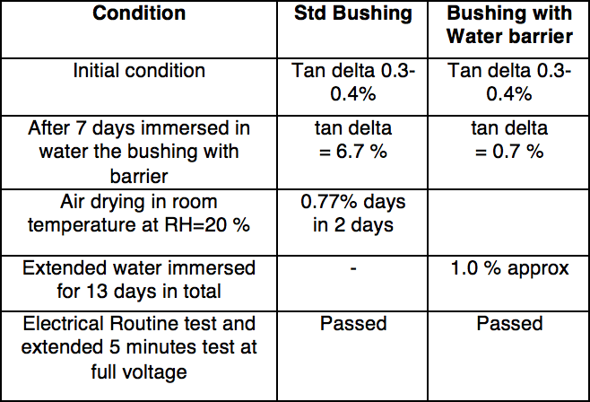 Testing the standard bushing versus one with a water barrier coating (under field evaluation) concluded that:
• compared to uncoated RIP, the barrier coating prolonged onset duration of moisture or water ingress into bushing layers by a multiple of about 80.
• increase in power factor, despite use of coating, proved that the coating is effective ONLY for handling purposes but not for long-term storage.
Design/Specification
• No migration of moisture must be possible through the external insulation to the RIP condenser body. All bushings rated voltage 52 kV and above shall have either fibreglass or alternative proven material that acts as moisture barrier between the RIP condenser body and the external composite insulator. Fig. 23 illustrates a fibreglass moisture barrier for RIP bushing designs. Other OEMs use pure resin or SF6 foam for similar purposes, also deemed acceptable.

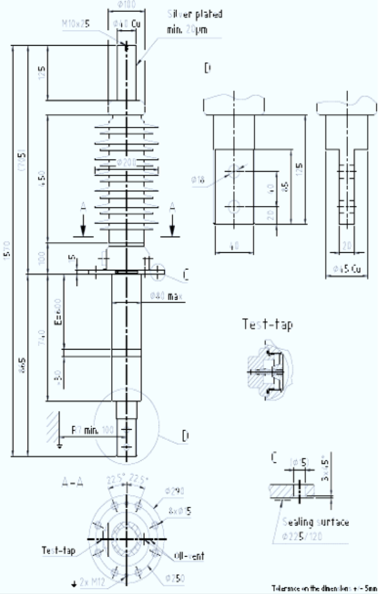
7. For purposes of inter-changeability and standardization, oil-air bushings of rated voltage 52 kV and above have to comply with standard requirements in terms of dimensions and rating (see Fig. 24), as already successfully implemented by one utility member.
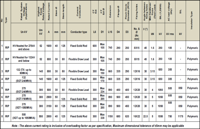
8. For replacement or refurbishment purposes on units already in service, it is recommended that the new bushing supplied exactly match existing dimensions in order to ensure bottom clearances are met, as per initial design, and to prevent substantial modification and need for retrofitting work on site;
9. All type tests and routine tests shall be carried out according to the latest requirements of IEC or IEEE standards. Type test reports and certificates must be submitted to users on delivery;

10. Partial discharge testing shall be performed in accordance with the latest IEC 60137 requirement(s) or routine measurements for detection of internal PD. These shall be, at maximum, virtually discharge free (i.e. ≤5pC at 1.05 Um/Ö3 and ≤5pC at 2.0 Um/Ö3 when more stringent requirement(s) apply). If a bushing fails the PD test, it is to be rejected and not to be reconditioned for later use in the system.
11. For those bushings having a draw lead connection, the transformer manufacturer shall ensure that the draw lead cable within the tube is insulated using thermally upgraded insulation material with minimal thickness of 1 mm. There must not be a significant rise in hot spot temperature of the bushing so as to prevent risk of arcing between draw lead to aluminium tubing during system fast transient phenomena.
12. When fixed solid conductors are used, the transformer manufacturer must ensure a flexible lead is provided between transformer and bushing to avoid any vibration or dilatation being transmitted during operation;
13. Current rating of supplied bushings shall be inclusive of an overload factor of at least 1.2 times maximum rated current for transformer rated capacity;
14. The test tap shall be manufactured from non-corrodible material and be sealed by means of a non-corrodible screw-on dust cover during service. A reusable (oil, heat and UV resistance) seal shall be provided to prevent moisture and/or other impurities from entering the test tap. Use of a nitrile rubber material with sufficient hardness is preferred in this regard;
15. Internal connection of the test tap to the outmost condenser foil layer is accomplished using a permanent electrical connection. Spring-loaded type internal connections are not recommended due to experience with poor performance due to loss of spring contact pressure over time;
16. Air insulated cable boxes on transformers shall have arc venting to prevent risk of damage to the cable box, dislocation of cables and breakage of bushings (see Fig. 25);
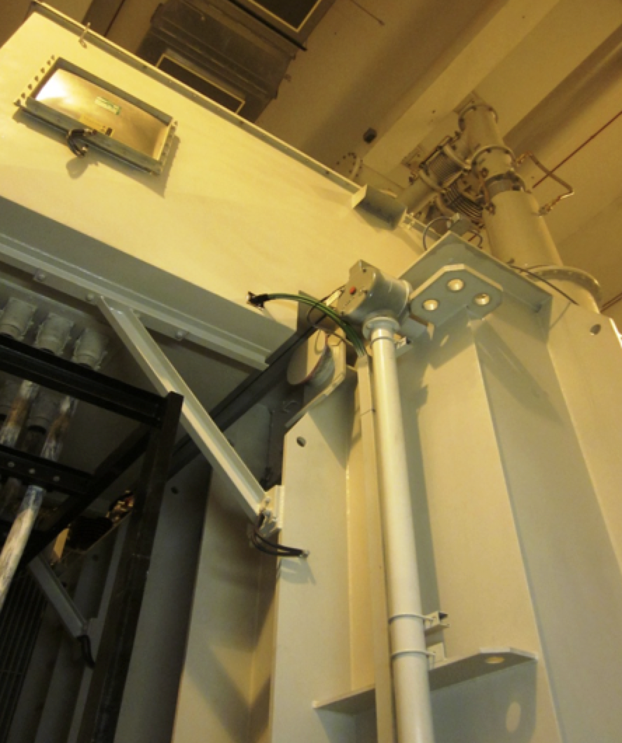
17. In regard to on-line monitoring systems for critical installations, it is the prerogative of users to study the suitability of different technologies that can assess bushing condition in the field. Fig. 26, for example, illustrates installation of bushing monitoring on a power transformer and findings of a case study are elaborated below:
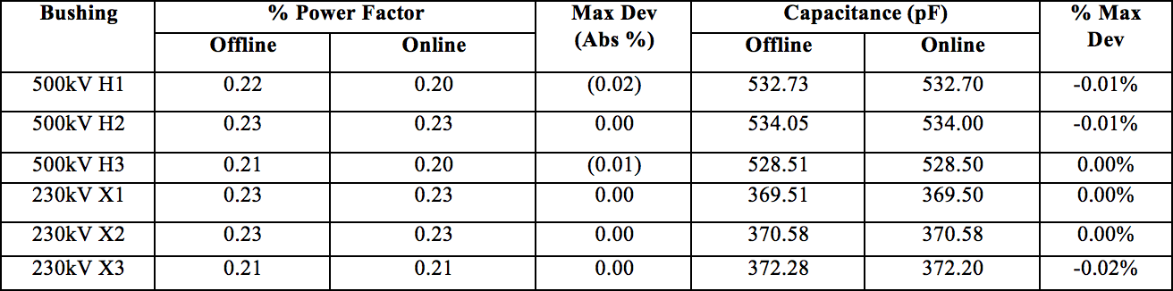
Findings have revealed that information from off-line and on-line monitoring mostly agree in the case of healthy bushings (refer to Table 4) and such a system can therefore serve as a tool to monitor relative change in bushing condition. However, benefits have to be assessed on a case-by-case basis prior to implementation, given the risks to equipment being monitored as well as the cost and reliability of such a monitoring system.
Case Study
Power Transformer 3×250 MVA, 500/230-11 kV
Bushing on-line installation: 2015
On-Line Measurements vs. 10 kV Off-Line Values
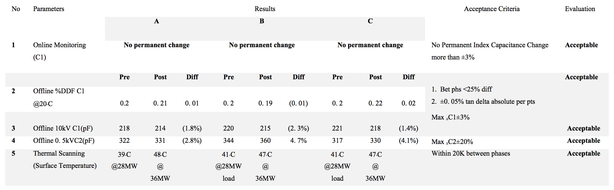
18. Use of resin impregnated synthetic fibre technology for dry bushings mitigates possible issues related to hygroscopic properties of epoxy resin impregnated bushings with conventional paper insulation. For example, TNB, embarked on a pilot project in 2013 using the new RIS technology at 170 kV. Results, shown in Fig. 27 and Table 5, indicated superior performance versus conventional RIP bushings.
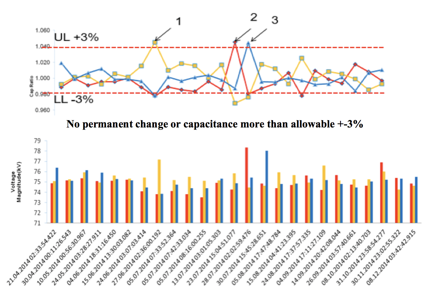
Table 5 summarizes measured parameters over the course of the evaluation period versus acceptance criteria established by the project team.
Overvoltage Protection
• Metal oxide surge arresters are an important part of transformer protection in reducing risk of a failure due to surges or transient activities in the system. All line terminals of a transformer should be protected by surge arresters.
Conclusions
Despite a relatively low failure rate given their population, failures of bushings can have a catastrophic impact on grid reliability, availability and safety. Conducting a survey and developing an ASEAN Bushing Guidebook yielded significant benefits in terms of standardizing and reviewing existing practices to ensure these are in line with best practices as well as the latest international standards. Several effective risk mitigation measures and improvements have been outlined based on experience from past incidents of failure. Effective implementation of these measures has helped improve overall bushing performance with reduced rates of failures among member utilities.
________________
RELATED ARTICLES:
Test Requirements for HV Bushings
Testing for Safety & Risks Affecting Operation of HV Cable Terminations, Bushings & Arresters