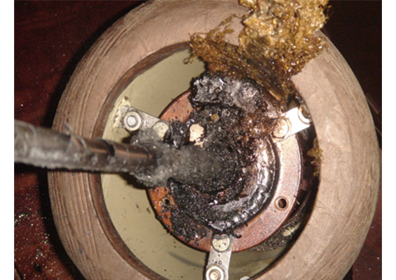
This edited contribution to INMR by Asset Manager Harry Gumilang reviews implementation of bushing maintenance at Indonesian TSO, PLN Persero and also discusses cases of bushing failures.
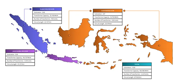
Fig. 1 provides an overview of PLN’s transmission assets across Indonesia. In total, PLN operates 1,013 substations, with a combined transformer capacity of about 153,724 MVA. The transmission network stretches over 60,811 circuit kms and includes 2083 power transformers. In the Sumatra region, PLN runs 234 substations with a total capacity of 28,454 MVA, connected by almost 19,936 circuit kms and supported by 425 transformers. The Java–Bali region has the largest share, with 580 substations and 1,320 transformers, giving it a capacity of 111,936 MVA and nearly 25,000 circuit kms of lines. The East region has 199 substations with a total transformer capacity of 13,334 MVA, supported by 340 units and more than 15,876 circuit kms. Meanwhile, PLN Batam, a sub-holding, manages 11 substations, 21 transformers, and a capacity of 870 MVA across about 192 circuit kms.
This distribution shows how PLN’s assets are spread across the country, reflecting both the scale and complexity of managing Indonesia’s transmission system. Each region plays an important role in ensuring electricity is delivered safely and reliably to millions of consumers.
Transformer bushings are essential parts of the power system, acting both as insulators and as electrical connectors that link transformers to power lines and other equipment. Without them, transformers cannot safely or effectively connect to the wider electrical network.
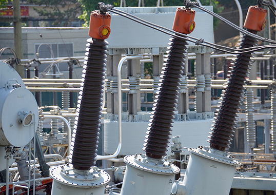
Perusahaan Listrik Negara (PLN), Indonesia’s state-owned utility, manages a large fleet of transformers—2,083 units with a combined capacity of 153,724 MVA. These transformers are used to step voltage levels up or down, ensuring efficient transmission and distribution of electricity. With such a vast inventory, it is estimated that PLN operates around 14,000 bushings across different voltage levels, ranging from 70 kV to 500 kV. Each bushing is selected and installed according to its voltage requirement to maintain safe and reliable operation.
Given their role, bushings are critical to stability of the grid. They must not only provide strong electrical insulation but also withstand demanding operating conditions over many years. Regular inspections, testing, and maintenance are therefore vital to detect early signs of deterioration. Preventive measures such as cleaning, oil checks, and timely replacement help extend service life and reduce the risk of sudden failures.
Bushing Maintenance
Power transformer bushings experience various failure patterns during their operational life. One prevalent issue involves a decline in insulation quality within the bushing, irrespective of whether it is of the oil-impregnated or resin-impregnated paper type. This decline occurs due to imperfections during the manufacturing process or ingress of moisture. Another set of failure patterns pertains to problems with the center tap component. For example, one common challenge involves the detachment of pins from the center tap. This disconnect can compromise the integrity of the bushing’s electrical connections. Similarly, another failure pattern arises when the pins fail to connect securely with the cap component. These challenges related to the center tap are critical as they can lead to electrical issues and hinder the bushing’s overall performance.
Addressing these operational challenges is essential to maintain the reliability of transformer bushings. Regular inspections and maintenance practices are crucial for identifying and rectifying these failure patterns, ensuring the seamless operation of power distribution systems and minimizing the risk of disruptions.
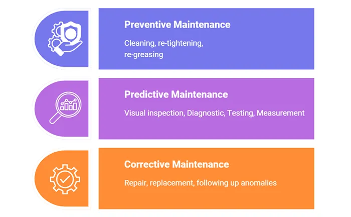
To ensure reliability and efficiency of their power transformers, PLN employs a variety of maintenance methods. These approaches are crucial for establishing an effective maintenance plan. PLN’s maintenance strategy encompasses three primary types: preventive maintenance, predictive maintenance, and corrective maintenance. This diversified approach enables PLN to take proactive measures to prevent issues, anticipate potential problems, and promptly address and rectify any existing concerns. It plays a vital role in upholding the dependable performance of their power transformers, ensuring consistent and efficient electricity supply.
a. Preventive Maintenance
Preventive maintenance serves as a proactive approach to equipment upkeep, with the primary goal of preventing malfunctions and breakdowns. It involves scheduled and routine activities such as cleaning, tightening bolts and cable connections, replenishing lubricants, replacing standard materials, and assessing functionality of individual components. By adhering to this structured maintenance regimen, organizations ensure that their equipment remains in peak condition, minimizing the chances of unforeseen failures and promoting long-term reliability. This approach not only safeguards equipment but also contributes to cost-effective and uninterrupted operations
b. Predictive Maintenance
Predictive maintenance is a maintenance approach focused on foreseeing the condition of equipment. It achieves this by conducting meticulous inspections, measurements, and tests on the equipment. The results of these assessments are then meticulously analyzed, and interpreted to discern any impending issues. Subsequently, actions are planned accordingly to address any detected concerns. Predictive maintenance is sometimes referred to as condition-based maintenance (CBM) and is contingent on the phases and analyses undertaken, thereby enabling organizations to stay ahead of potential equipment problems, minimize disruptions, and optimize operational efficiency.
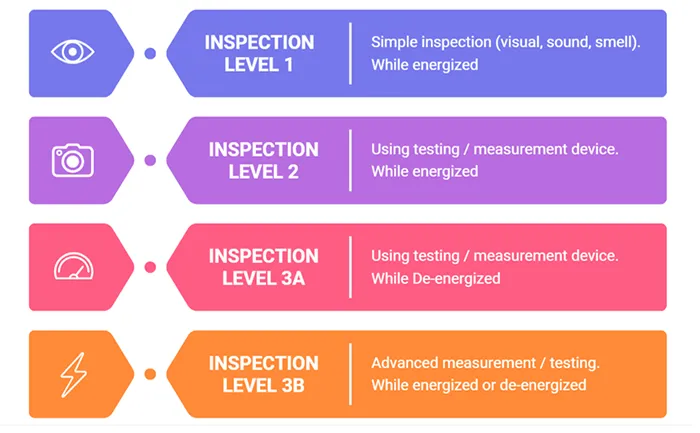
Types of inspection and measurement / testing in predictive maintenance:
• Inspection Level 1
Is an inspection or inspection that is visual, sound and smelly without using test equipment/measuring instruments. Such as looking at the condition of the bushing oil level, the condition of ceramic surface and possibility of leakage existence.
This initial inspection is categorized as a simple assessment carried out while the transformer remains energized. During this inspection, visual checks and basic assessments are performed to identify any visible issues or anomalies. This routine inspection helps in detecting obvious problems and ensuring the transformer’s continued safe operation.
• Inspection Level 2
It is a measurement / test using test equipment but the equipment remains in operating condition (online). The second level of inspection involves measurements while the transformer remains energized. It delves deeper into assessing the transformer’s performance by taking precise measurements and readings. These measurements provide valuable data about the transformer’s electrical characteristics and help in diagnosing any potential issues that may not be visible through a simple visual inspection.
• Inspection Levels 3.1 & 3.2
It is a measurement / test using test equipment and the equipment is in an off state (offline). The most comprehensive level of inspection is Level 3, which involves measurements while the transformer is dis-energized, and advanced diagnostic procedures. During this thorough inspection, the transformer is taken offline, and advanced diagnostic tests are conducted. These tests provide in-depth insights into the transformer’s condition, allowing for a detailed assessment of its health and the identification of any hidden or complex issues. Level 3 inspections are critical for ensuring the long-term reliability and safety of the transformer and its associated bushings.
By employing these three levels of inspections, PLN aims to systematically assess and maintain the transformers, including the crucial components like bushings. This proactive approach helps in detecting and addressing issues at various levels of complexity, ultimately ensuring the safe and uninterrupted supply of electricity to consumers.
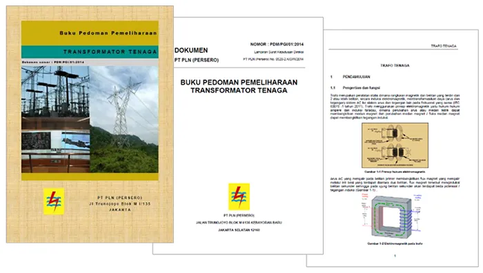
Since 1984, PLN has provided a power transformer operation & maintenance manual that can be used as a reference on how to maintain and operate a power transformer. This manual is gradually being developed along with the development of diagnostic technology, experience and best practice.
c. Corrective Maintenance
Corrective maintenance is a type of maintenance that serves to restore or improve the ability of equipment that has decreased.
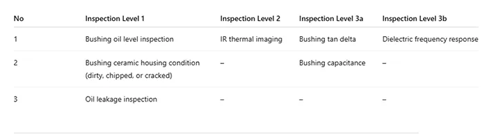
Table 1 describes different levels of inspection for transformer bushings. Each level adds more detail and requires more advanced tools compared to the previous one. The purpose of this structure is to make sure that problems can be detected early, starting from simple visual checks up to detailed diagnostic testing.
At Inspection Level 1, the checks are mostly visual and straightforward. This includes looking at the oil level inside the bushing, checking the ceramic housing for dirt, chips, or cracks, and making sure there are no signs of oil leakage. These inspections can be done by operators during routine patrols or regular maintenance without special equipment.
Inspection Level 2 involves the use of infrared thermal imaging. This method helps detect abnormal heating or uneven temperature distribution, which may indicate internal issues or poor connections. Although still relatively simple, it gives more insight than visual inspection alone.
For Inspection Level 3a, more advanced electrical tests are carried out. These include measuring the bushing’s tan delta (dissipation factor) and capacitance. These values provide important information about the condition of the insulation and whether there is any aging, moisture, or partial discharge activity inside the bushing.
Finally, Inspection Level 3b uses dielectric frequency response testing. This is the most detailed diagnostic method in the table and is usually performed when there are concerns raised by earlier inspections. It gives a deeper view of the insulation condition and can help identify moisture ingress or other hidden defects.
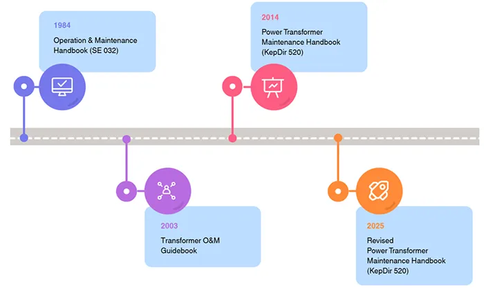
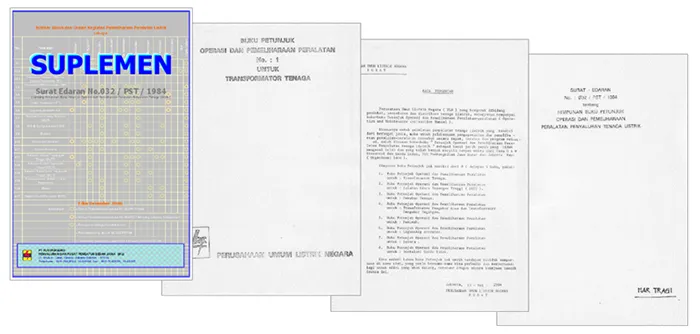
Operation and maintenance handbook for power transformers, released in 1984. The scope of the discussion is still simple considering that transformer diagnostics are not yet sophisticated. This book covers the components and functions of a power transformer and how to inspect them and the limitations of oil and electrical testing.
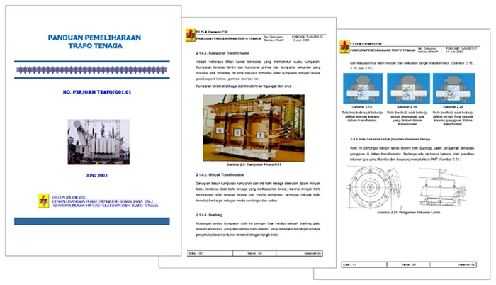
The power transformer maintenance Guidebook, released in 2003, was more detailed. It not only discusses details of the components on the power transformer but also the test scheme, test steps, test materials and test forms.
Bushing Failure Modes
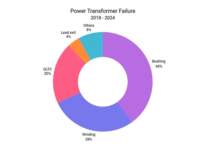
The chart shows the main causes of power transformer failures between 2018 and 2024. From the data, it is clear that bushing problems are the leading cause, making up about 40% of the total cases. This suggests that bushings remain one of the weakest points in transformer reliability.
The second biggest contributor is winding failure, which accounts for 28%. Winding issues often come from insulation breakdown, overheating, or mechanical stress during operation. After that, OLTC (On-Load Tap Changer) failures represent 20%, reflecting the fact that this moving part is also prone to wear and operational stress. Other failure points are much smaller in comparison. Lead exit problems only make up 4%, while other causes together account for 8%.
In summary, most transformer failures during this period were concentrated in bushings and windings. These two components together represent more than two-thirds of all cases, highlighting the importance of close monitoring and preventive maintenance in these areas.
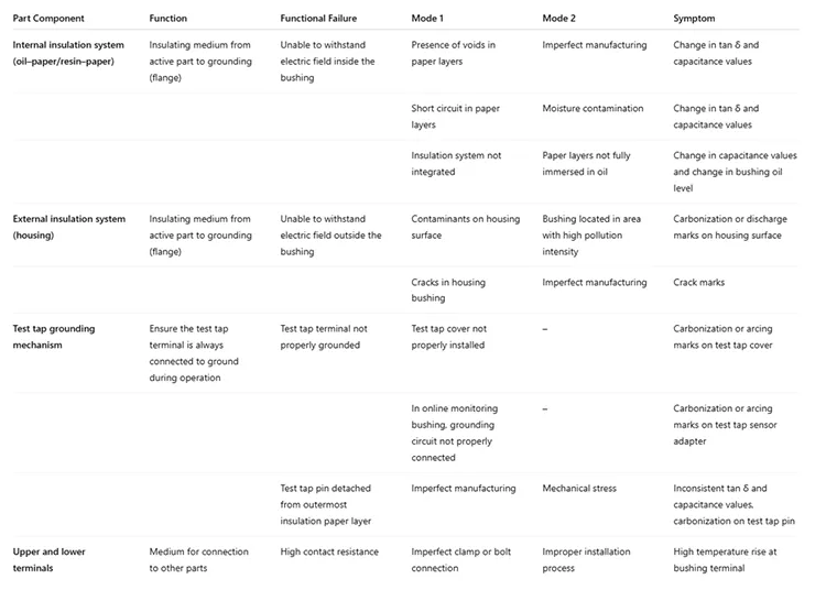
Table 2 reviews possible failures in transformer bushings, along with their causes and symptoms. The bushing is an important component that provides insulation between the energized parts and ground, so any weakness can lead to serious problems. The analysis is divided into several parts: the internal insulation system, the external insulation system, the test tap grounding mechanism, and the upper and lower terminals.
For the internal insulation system (oil–paper/resin–paper), failures occur when the insulation cannot hold the electric field inside the bushing. This can happen because of voids in the paper, short circuits in the paper layers, or poor integration of the insulation system. Other causes include moisture contamination or paper that is not fully immersed in oil. These conditions usually show up as changes in tan δ and capacitance values, or shifts in the oil level inside the bushing.
The external insulation system (housing) can also fail if the surface is contaminated or if there are cracks in the housing. Pollution in the environment or poor manufacturing quality are common causes. The symptoms are usually clear to see, such as carbonization marks, discharge traces, or visible cracks on the surface of the bushing.
The test tap grounding mechanism has the role of keeping the test tap terminal connected to ground. Problems may happen if the test tap cover is not fitted properly or if the grounding circuit in online monitoring systems is not correctly connected. Another critical issue is when the test tap pin becomes detached from the outermost paper layer. This can be due to poor manufacturing or mechanical stress. When this happens, the symptoms may include inconsistent tan δ and capacitance readings, as well as carbonization or arcing marks around the test tap area.
Finally, the upper and lower terminals can develop high contact resistance if clamps or bolts are not properly tightened or if the installation process is not done correctly. The main symptom here is a noticeable temperature rise at the terminal, which can be detected during inspections.
Case Studies
1. Arcing on Bushing Due to Improper Draw Rod Tightening
In this case, the disconnection between the bushing and the transformer winding in a 500 kV unit occurred due to loosened bolts on the bushing stud as a part of draw rod of the bushing. When the bolts securing the bushing lose their tightness, the connection can separate, compromising both electrical continuity and equipment reliability. Immediate corrective action—tightening the bolts—was required to restore proper connection and ensure operational integrity.
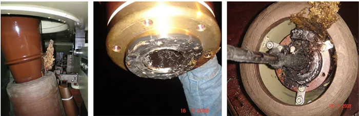
A common issue with bushings is the loosening of the mechanical connection to the transformer winding. This reduction in bolt tightness can increase contact resistance at the joint. As resistance rises, localized heating may develop, leading to hotspots at the connection. These thermal effects can accelerate the formation of dissolved gases, which are detectable through Dissolved Gas Analysis (DGA) testing, serving as an early diagnostic indicator of the problem.
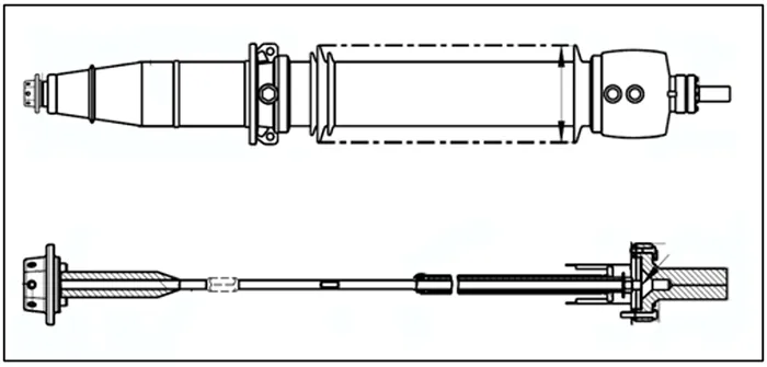
If this problem is ignored, it can lower the performance of the bushing and eventually affect the whole transformer. That’s why regular checks and DGA tests are important, as they help spot and fix the issue early, keeping the system safe and reliable.
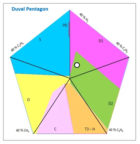
The Duval Pentagon is a method used in Dissolved Gas Analysis (DGA) to check the health of power transformers. If the results point to D2, or “high energy discharge,” it means that a serious electrical event or strong discharge has happened inside the transformer. D2 usually shows up when there are large surges of current or other electrical problems that release a lot of energy in the transformer. This is an important warning sign that something serious may be going on and needs quick attention. Ignoring it could cause more damage to the equipment. Because of this, any D2 findings should be reviewed right away with the help of skilled engineers or transformer experts, so the problem can be solved and the system can keep running safely and reliably.
2. Inconsistent Value of Tan Delta Due to Disintegrated Test Tap Connector/Pin
In 2024, the low-voltage bushing of a 500/150 kV power transformer was found to have a very high tan delta value, averaging around 3.08%. Because this result was far above the normal range, the bushing was eventually replaced. After the replacement, a tear-down investigation was scheduled to better understand the root cause of the problem.
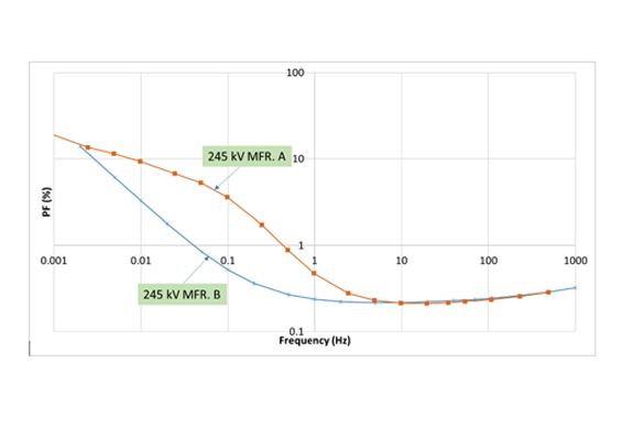
As part of the investigation, a Dielectric Frequency Response (DFR) test was carried out. This test measures the tan delta not only at the standard frequency of 50 Hz but also across a wider range of frequencies. By looking at how the tan delta changes at different frequencies, engineers can get a clearer picture of the condition of the insulation and identify whether the issue came from aging, moisture, or other types of defects inside the bushing.
A tan delta value of around 3.08% is considered high, since in normal practice the acceptable limit is usually close to 1% or lower. When the tan delta rises above this limit, it often points to problems in the insulation system, such as partial discharge activity, moisture ingress, or deterioration of the dielectric material. These issues increase electrical losses and reduce the overall reliability of the transformer.
By carrying out both the replacement and the detailed investigation, the goal was not only to restore the transformer to safe operation but also to learn from the failure. The findings from the DFR test and the tear-down study can provide valuable insight into how the insulation aged, what type of stress contributed to the failure, and how similar problems might be prevented in the future. This kind of approach helps ensure long-term reliability of high-voltage equipment in the power system.
The accepted limit for tan delta is 1%. At frequencies of 50 Hz and 70 Hz, the measured values are below this limit, so they can be considered normal. However, at 30 Hz, 10 Hz, and 8 Hz, the tan delta values are much higher than 1%. This condition suggests that there may be an internal anomaly in the bushing, such as insulation deterioration or partial discharge activity. Unfortunately, this issue was only identified after the bushing had already experienced a breakdown.
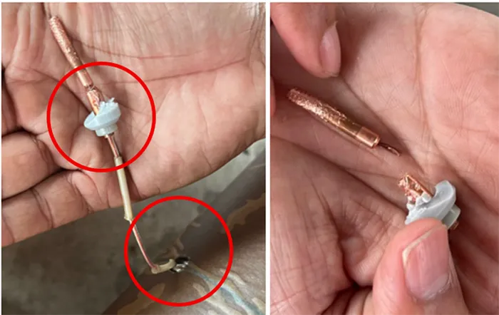
The investigation revealed that one of the wires in the test tap electrode or pin was frayed and almost broken. This condition could reduce the reliability of the electrical connection in the bushing. It is suspected that the damage was caused by excessive rotation of the pin during the installation of the cap or cover.
Such mechanical stress can weaken the internal connection over time, eventually leading to higher resistance and possible electrical problems. This finding highlights the importance of careful handling during assembly and maintenance, as small mechanical errors can create serious issues in high-voltage equipment.
3. Deterioration of Bushing Insulation Caused Arcing between Rod & Grounding Flange
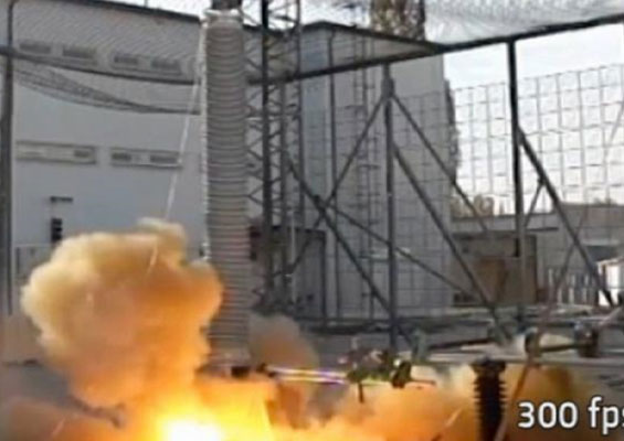
In 2012, a 500/150 kV power transformer experienced a failure that eventually led to a fire. Once the situation was brought under control and the transformer could be accessed safely, an investigation was carried out to find the cause of the incident.
Records showed that before the failure, the low-voltage bushing had a tan delta reading of 0.95%. This value was already close to the upper limit of what is generally considered normal for a bushing. A reading at this level can be an early signal that the insulation system is weakening, and if not monitored closely, it may develop into a more serious problem.
A tan delta value that approaches the normal limit should be treated with caution, as it often points to early signs of insulation deterioration. When the insulation inside a bushing starts to lose its quality, the electrical losses increase and the risk of partial discharge or overheating becomes higher. If these issues are not identified and corrected in time, they can weaken the bushing further and put the entire transformer at risk.
In this case, the reading of 0.95% may have been an early warning that the bushing was no longer in good condition. Without proper follow-up actions, such as closer monitoring or preventive maintenance, the weakness developed into a serious failure that ended with the transformer fire. This shows how important it is to pay close attention to test results that are already near the limit, even if they are still technically within the acceptable range.
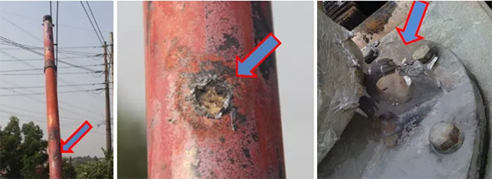
Arcing found on the bushing rod is a clear indication that electrical discharge has also taken place in the inner insulation layer, which connects the bushing rod to the grounded flange. This condition shows that the insulation between the rod and ground is no longer working as it should.
The reduction in insulation strength can happen for several reasons. It may be caused by moisture entering the insulation, the presence of small voids or air pockets, or partial short circuits within the paper-foil layers. Each of these factors weakens the dielectric material and creates a path for electrical stress, eventually leading to arcing.
Such findings are important warning signs, because once the insulation begins to fail, the risk of more severe damage to the bushing and transformer becomes much higher. Careful monitoring, testing, and timely maintenance are needed to prevent this condition from escalating further.
Conclusions
PLN Indonesia, as the utility in charge of managing transmission assets, holds the responsibility of maintaining power transformers, where bushings are among the most critical components. Since the 1980s, PLN has been developing transformer and bushing maintenance concepts. Over the years, the methods used to assess transformers and their components have evolved significantly, not only in terms of philosophy and maintenance concepts but also with the technologies applied.
Despite these efforts, within the past ten years there have still been several cases of power transformer failures linked to bushing problems. The root causes have varied, ranging from insulation system degradation, improper terminal installation, to anomalies in the test tap circuit. These cases highlight how important bushings are for overall transformer reliability.
With the maintenance methods developed and implemented by PLN, it is now possible to carry out condition assessments of power transformers, including their on-load tap changers (OLTCs) and bushings. This allows a quick response when a transformer, OLTC, or bushing shows signs of poor condition. At present, PLN is also exploring use of dielectric frequency response (DFR) testing as a way to gain deeper insight into bushing health, providing information that may not be fully captured by earlier diagnostic methods.
References
a. PLN Power transformer maintenance guidebook
b. PLN Tripping performance and experience sharing of JMCC
c. Bushing maintenance guide by JMCC
d. CIGRE Brochure 445 – Guide for transformer maintenance
e. CIGRE Brochure 755 – Transformer bushing reliability