Failure of a HV suspension or tension insulator is clearly something that any electric utility or insulator manufacturer wishes would never occur. However, it is unrealistic to expect that any network component will exist forever and never fail. Therefore, one can reasonably anticipate that some insulators will fail in service after a certain time. What both manufacturers and users alike hope is that this number be kept as small as possible, meaning that the failure rate of HV line insulators should be extremely low.
Fortunately, most HV insulators available these days have reached a high level of reliability. But how low is this rate and what does it really mean? Also, is a particular failure rate meaningful if taken by itself? To answer these types of questions, it is first necessary to define what a failure is and to examine the consequences.
In this 2006 contribution to INMR, the late insulator expert, Dr. Claude de Tourreil offered his views on these issues.

What Constitutes Failure?
A HV line insulator performs two functions: mechanically, it holds the conductor at a certain distance from the tower and the ground; and electrically it provides the necessary insulation to ground. Therefore, one way to define an insulator failure is when either or both of these functions are no longer being fulfilled. A less technical way to define failure is to say that an insulator has failed whenever it is removed from service because of unsatisfactory service experience. But, this second definition of failure can be misleading. For example, that criterion was used in the survey of service experience with composite insulators done many years ago by CIGRE WG 22-03. Unfortunately, this led to an unjustifiably high figure for number of reported failures because, in many cases, utilities supplying data decided to remove all insulators of a particular design simply because a small number had failed.
Different insulator types fail in different ways. The failure modes of toughened glass or porcelain insulators are quite different from the failure modes of composite insulators, and this may have consequences on continuity of service. Because of this, it can be difficult to compare failure rates of different types of insulators.

Causes & Modes of Insulator Failure
Many factors can bring about failure of an insulator. For example, the insulator can contain a tiny manufacturing defect, which over time will grow and lead to failure. That defect can be located within the dielectric part of the insulator, the metal fittings or in the materials used to keep the dielectric part and the metal fitting together. The failure of an insulator could also be caused by service conditions. For example, an insulator can separate when abnormally high ice accretion or heavy wind conditions cause the mechanical load applied to exceed the unit’s rated value.

Similarly, extreme pollution levels can cause degradation of the dielectric or corrode the metal fittings, thereby preventing the insulator from fulfilling its electrical or mechanical functions. A flashover leading to a power arc of extended duration can also bring about the failure of the dielectric or the failure of the metal fittings. Finally, various acts of vandalism can also cause insulator failure.
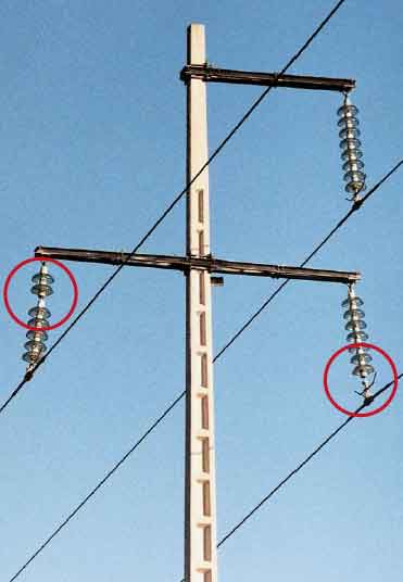
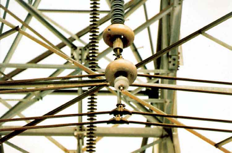
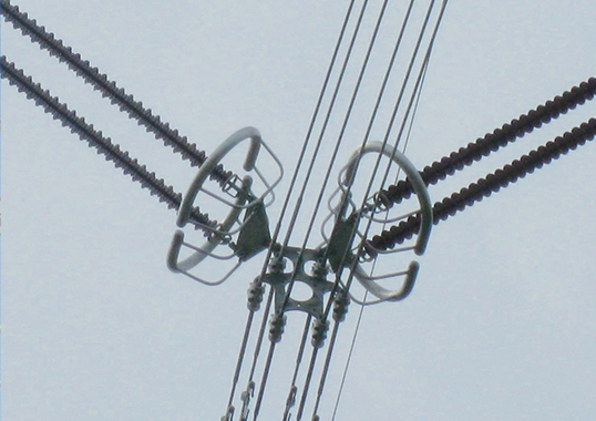
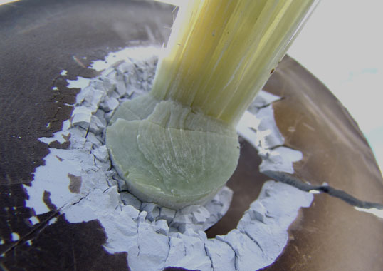
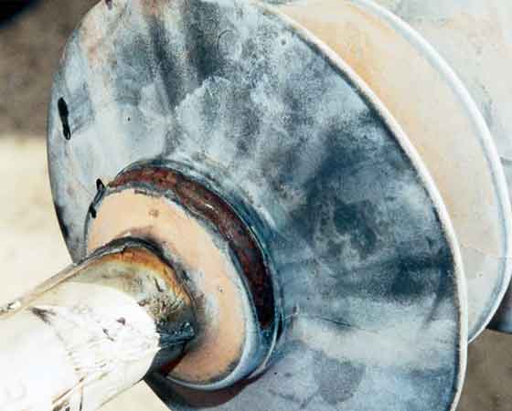
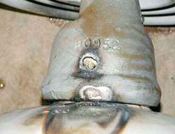
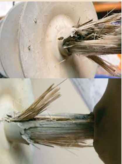
Fig. 4 shows a failed toughened glass insulator that is part of an insulator string supporting a conductor. Only a close examination of this insulator can determine the actual cause of failure. Fig. 5 shows an EHV composite insulator, made over 30 years ago, the failure of which occurred close to the live end. Only two or three sheds as well as the field grading device are still connected to the live end fitting. Here the failure was likely associated with an interface problem.
While the insulators in Fig. 4 failed electrically, they still fulfilled their mechanical duty. It is probable that the insulator in Fig. 5 first suffered an electrical degradation that subsequently led to mechanical failure.

Effect of Insulator Failure on Electrical System
When an insulator fails mechanically, it is no longer relevant to consider any electrical function. By contrast, when an insulator fails electrically, it may lose mechanical function, or, in some cases, still offer the mechanical strength required to allow normal operation of the line for an extended time. These different scenarios are usually a consequence of the inherent characteristics of different types of insulators.
The effect of insulator failure on operation of an electrical system also depends on design of the tower. The mechanical failure of a composite insulator, a glass or porcelain cap & pin or a porcelain long rod insulator will in all cases cause a drop of the conductor if no other insulator is utilized in parallel.
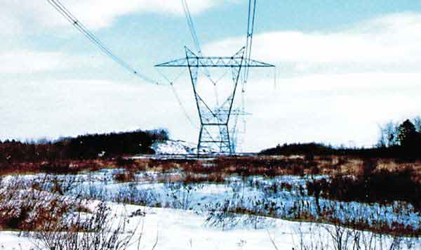
The quad bundle conductor associated with the failed composite insulator of Fig. 5 did not fall to the ground because it was held by two insulators in a V configuration. Fig. 7 shows the tower with the three V insulator arrangements. Even though it was the right-hand side of the V of the right phase that failed, the clearance to tower was still sufficient to hold the service voltage. The situation would have been more favorable had the left insulator of that V failed because then the conductor bundle would have swung further from the tower.
This same analysis would of course also apply to the left phase. However, should either of the two insulators of the center phase have failed, the clearance to the tower would no longer be sufficient and service would have been interrupted.
The situation becomes more complicated when an insulator fails electrically but not mechanically. It is assumed that a long rod porcelain insulator cannot fail electrically without also failing mechanically. By contrast, a composite insulator that has failed electrically may still have sufficient mechanical strength to hold the conductor. But since there is only one insulator between the conductor and the tower it can no longer hold the service voltage.
The most favorable case is for cap & pin glass or porcelain insulators because, since strings are usually made up from more than two insulators, the failure of only one unit usually allows the string to still hold the nominal voltage of the line. This is illustrated in Fig. 4. The failed glass insulators have no detrimental impact on performance of the string. The same would be true if the string consisted of porcelain cap & pin insulators.

Detection of Failed Insulators
Determination of the failure rate of insulators requires knowing both the total number of insulators that have been installed and the number of insulators that have failed. It is usually simple to determine the number of insulators of any type that have failed mechanically. As indicated above, it is highly unlikely and maybe even impossible for a porcelain long rod insulator to fail only electrically.
The detection of glass cap & pin insulators that have failed electrically is simple and based only on visual examination. In the strings shown in Fig. 4, all the insulators are electrically sound except for those whose glass shells are clearly missing. Should this cap & pin string have been of porcelain, however, it would become more difficult to locate the defective unit even though methods for such detection are available. At the same time, electrical failure of any single cap & pin insulator is generally not critical since it generally does not lead to service interruption. Therefore, it is usually sufficient to detect failed cap & pin insulators only once failure of the entire string has occurred.
remained intact for 6 months.
Since the electrical failure of a composite insulator will affect continuity of service, it is desirable to be able to foresee such failure early enough to avoid service interruption. The electrical degradation of composite insulators takes place over a period that, in most cases, is long enough to permit line inspection to locate the electrical defect before it creates a service interruption. Different methodologies have been proposed in this regard.

Insulator Failure Rates
The failure rates of any given type of insulator is something that can only be assessed by the utilities using these insulators. They are the only ones to know how many such insulators have been installed and how many have failed. Understandably, insulator manufacturers are also interested to know these figures because they are in a position to take the measures necessary to improve that rate.
The failure rate of a specific insulator type may be used as a basis for assessing its quality. In this case, all failures – mechanical and electrical – should be taken together.
However, from the utility point of view, it is also important to know the failure rate evaluated in terms of its impact on the reliability of the electrical system where the insulators are installed. In this case, it is more logical to determine the failure rate of an insulator type based on the number of failed insulators that led to an outage. When selection of a particular insulator type is based mainly on failure rate, it is particularly important to distinguish between these two different assessments of what really constitutes failure.
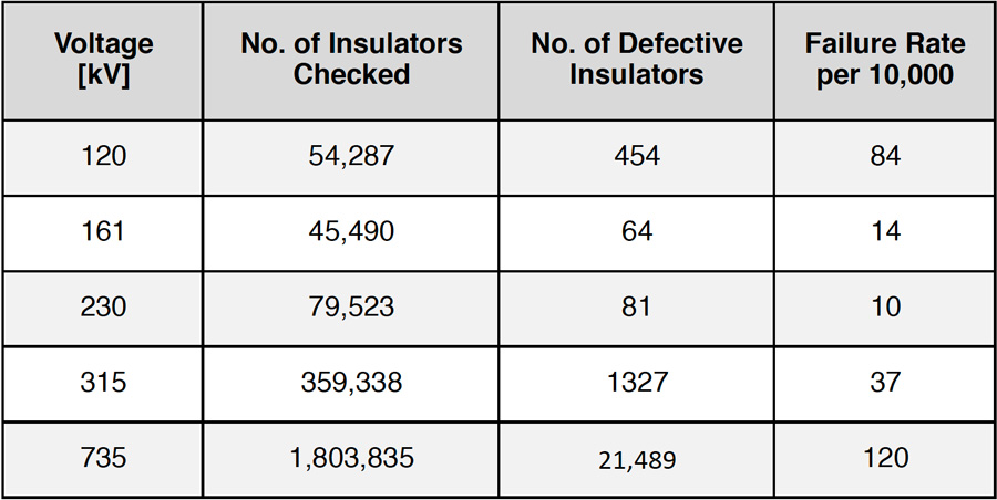
The failure rates presented in Table 1 are based on the numbers of insulators found defective during line inspection and can be used to assess the quality of specific types of porcelain cap & pin insulators. Such high rates confirm that these insulators (which are no longer manufactured) were of questionable quality.
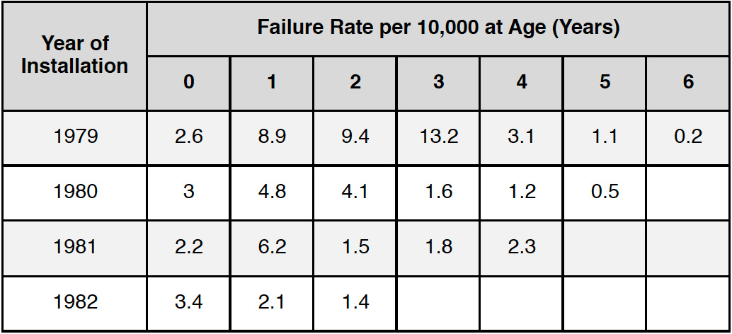
The failure rates of toughened glass insulators presented in Table 2 indicate that the quality of these insulators, already better than the porcelain insulators shown in Table 1, has improved over the years. These rates are based on the total numbers of insulators that have failed (mechanically or electrically). Unfortunately, they do not give any information on the impact these failures have had on the reliability of the line – a point that is certainly of great importance to any electric utility.
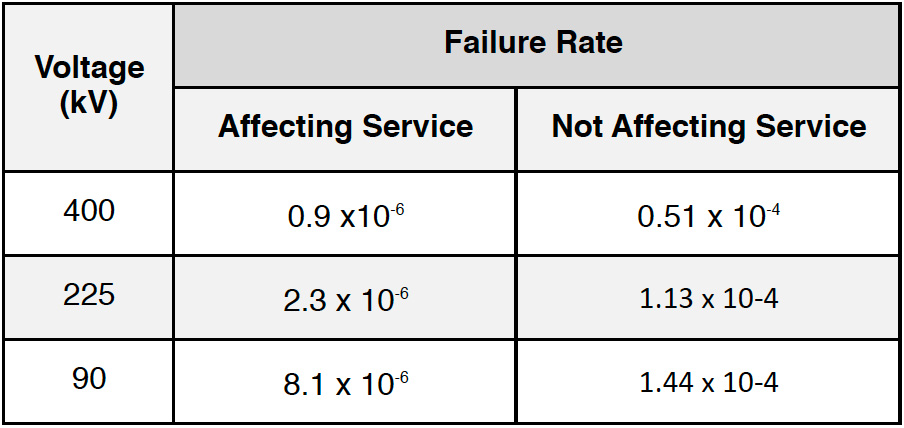
Table 3 illustrates the importance of distinguishing between mechanical failures that affect the continuity of service and electrical failures that (in the case of cap & pin strings) usually do not. As can be seen, failure rates affecting service are about 50 times lower than failure rates not affecting service.
Table 3 applied to about 10 million cap and pin insulators of which 92% are toughened glass and 8% are porcelain. The increase in failure rate as system voltage decreases may well be related to vandalism. It should be noted that failure rates of quality porcelain cap & pin insulators are likely similar to those in Table 3.
The failure rate for composite insulators quoted in a past CIGRE survey was found to be on the order of 10-4 per year. This number corresponds to failures that affected service. However, these numbers include failures of early designs of composite insulators and one can reasonably expect that the latest generation has a far lower failure rate

Conclusions
Knowing the failure rate of a given type of insulator can be a useful tool on which to base expectations for long-term performance. However, failure rate value by itself may not be sufficient to fully assess the effect such failures have on performance of an electrical system. It is also important, especially for the utility, to know if the failure of a given insulator will cause a line drop and/or an interruption of service. In this respect, utility engineers should recognize that line design is also important.