Arrester housings have properties and design parameters not common to most insulators. While a composite insulator is made primarily of polymer rubber on the outside and a fiberglass rod or tube on the inside, polymer-housed arresters feature a rubber material on the outside and a strength member binding the MOV disks beneath. Porcelain used to be the only arrester housing available but that changed in the late 1980s with introduction of polymer-housed units for distribution applications. Not long afterwards, polymer housings also became available for station class arresters.
While conversion from porcelain to polymeric housings was rapid and complete for distribution arresters due to an inherently safe failure mode, conversion from porcelain in the case of station class arresters is still underway. Both housing types are still being designed and manufactured.
This edited past contribution to INMR by arrester expert, Jonathan Woodworth, reviewed the key aspects of housings that need to be considered when specifying and applying surge arresters.
Types of Arrester Design
There are three fundamental arrester designs:
Type 1:
This is the porcelain-housed arrester where the housing provides the strength and also serves as protection against the environment. During assembly, end caps are attached to the porcelain and the metal oxide disks are inserted into the housing (see Fig. 1).
Type 2:
Referred to as a hollow-core polymer-housed arrester, this design consists of a fiberglass tube that has a rubber material molded over its external surface. The end caps are attached to the fiberglass tube and the disks are inserted into the tube (see Fig. 2).
Type 3:
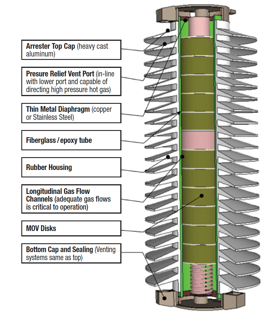
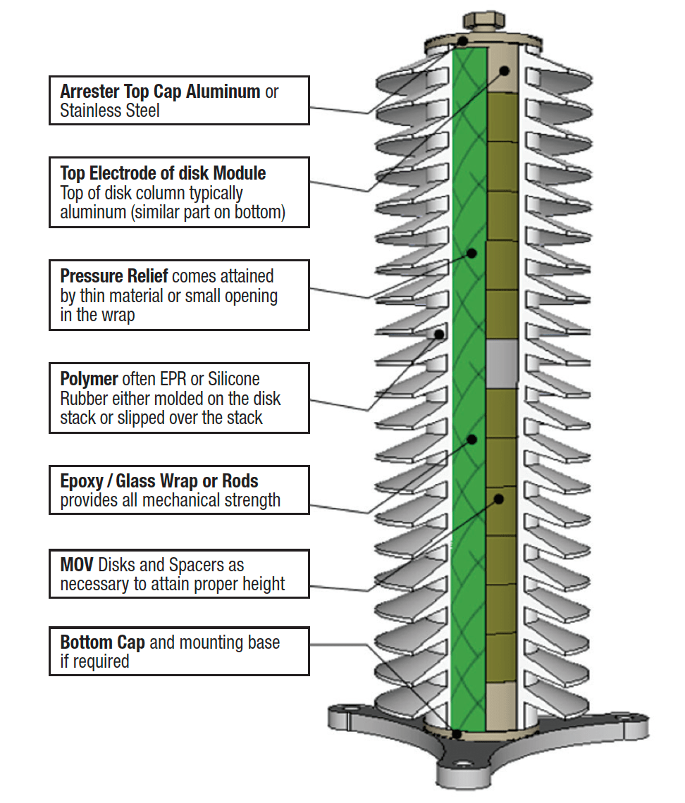
Referred to as a polymer-housed arrester design, disks are assembled into a stack that is either wrapped with a fiberglass/epoxy material or compressed into a module with end caps and rods or straps. A rubber housing is molded directly onto or slipped over the disk module. If slipped over the module, there is usually silicone grease or some RTV rubber compound applied to the interface between rubber and module (see Fig. 3).
Key Housing Parameters
Creepage Distance
Creepage distance is the distance on the surface of the housing from high to low voltage end (see Fig. 4). This parameter is critical when an arrester is being applied in areas where there is salt, industrial or other contamination. For example, once a contaminated arrester housing becomes damp, external leakage current begin to flow to ground. If these currents grow too high and enough charged particles are created along the surface, there will be a flashover, as with any standard insulator.
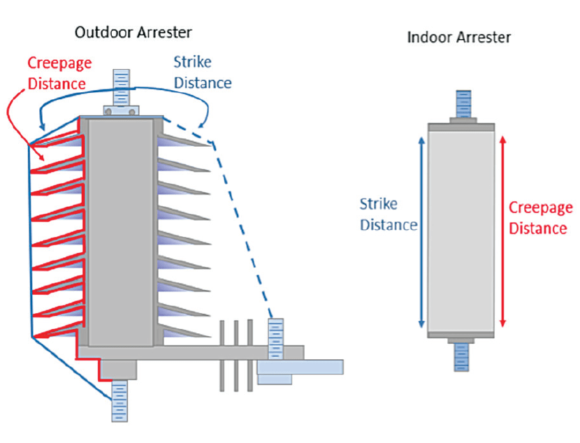
Flashovers can even occur at normal system voltage, i.e. no impulse is required to initiate flashover. Since arresters are unable to mitigate this type of flashover, their creepage must be increased to a level necessary to prevent it. IEC Standard 60507 provides guidance for selecting this distance based on ESDD levels in the area of application. Creepage distances typically range from 25 mm/kV to 35 mm/kV of applied voltage. While here is no agreed formula for predicting insulator power frequency flashover based on creepage, an estimate of 0.5 times the gap withstand voltage yields a conservative value. In this case, the gap is given as strike distance. For indoor application of an arrester, creepage distance of the housing needs only be the straight-line between HV and LV electrodes.
Strike Distance
This is the straight-line distance from high to low voltage end. Withstand voltage of an arrester housing is a function of this parameter.
Power Frequency:
U50FO = 750 2 ln(1 + 0.55d) (kV crest, m) for d < 1 m
U50 =U50FO (1.35K – 0.35K ) for d > 1 m and K = .5
Switching Surges : U50FO = 1080 ln (0.46 d + 1) (kV crest, m)
Lightning Surges: U50FO = 500 d 0.6 (kV crest, m)
where U50FO is flashover voltage of the housing, K = a gap factor for arrester housings, d = distance in meters. IEC 60071-2 provides more detail on these equations.

Self-Protecting Property
The above formulae can accurately predict when an arrester housing will flashover based on height. But the voltage across the housing will only attain such levels if there are no MOV disks inside. This self-protecting characteristic of arresters makes the arrester housing unique among insulators and also makes ‘strike distance’ a non-essential parameter to consider with applying arresters (although still important in design).
Effect of Altitude
Altitude of application affects flashover of insulators and this also applies to arrester housings. However, again, the MOV disks clamp the voltage across the housing to levels that should never be high enough to cause flashover. This can be verified using the following formula for reduction in flashover voltage based on altitude:
δ=e-A/8150, where A is altitude in meters and δ is change in withstand voltage.
For example, if the altitude of application is 3000 m, flashover voltage of the housing will be decreased by 30.8%. If arrester residual voltage can be higher than this value, there may be an issue with strike distance. Altitude also affects power frequency withstand voltage of arresters by this same percentage. If an arrester is being applied in an area with high ESDD, the altitude effect must be considered in housing design.
Mechanical Strength
Arresters typically support only themselves and their strength requirements are therefore far less than in the case of most insulators. However, arresters do need to withstand events whereby fault current flows for several seconds through the arrester. Fault currents can produce significant forces in many directions. Arresters can also be called upon to support one end of a short length of conductor and in this case may need extra cantilever strength. To meet these requirements, housings and terminals are typically designed with some minimal strength levels that, while not mandated in the standards, have instead become selling points between the different competing manufacturers. All strength types, i.e. cantilever, tensile, moment, burst and torque are provided by specific parts of the arrester. Mechanical strengths can be best summarized by each different arrester type:
Porcelain-Housed
The physical strength of an arrester depends on the strength of the bolts used in end caps, the end caps themselves (i.e. castings), interface strength between end caps and porcelain as well as on the porcelain housing. The housing in this type of design provides both environmental/seal protection and mechanical strength to the arrester.
Hollow Core Polymer-Housed
Most of the strength of this arrester design comes from the composite tube that runs the length of the housing. Polymer rubber is applied by various means to the outside of the tube to give it creepage distance but does not offer additional mechanical strength. As with the porcelain-housed arrester, strength of the interface between metal end caps and composite tube as well as connecting bolts and the fundamental strength of the end caps are the sources of arrester strength. The rubber housing offers only environmental protection.
Polymer-Housed Arrester
As with the hollow core design, the rubber housing offers no added mechanical strength to an arrester, which instead comes from composite rods, hoops or wrap that bind the internal MOV disks. Interface strength between end caps and composite parts is critical for tensile strength and burst strength during a fault event. The rubber housing in such designs also offers no burst strength. If pressure inside the arrester increases, the composite mechanical structure does not contain this pressure build-up. Rather, gases burst easily through the housing. In fact, prior to an event such as slow over-temperature failure, the rubber may even inflate like a balloon prior to bursting and leaving a hole in the side. It is this low burst pressure parameter that resulted in non-fragmenting arrester designs being so quickly accepted in the distribution market during the 1990s.
Ageing
The rate at which an arrester housing ages only became a parameter of interest with introduction of polymer-housed arresters. Modern porcelain arresters appear to have an infinite ageing characteristic and units removed decades after installation show no signs of age on the porcelain. Upon introduction of the polymer housing, however, the question of ageing became a consideration. The term hydrophobicity was also introduced with the polymer arrester. This parameter is a measure of surface tension to water. When a surface is hydrophobic, water beads on the surface while, when hydrophilic water planes out instead.
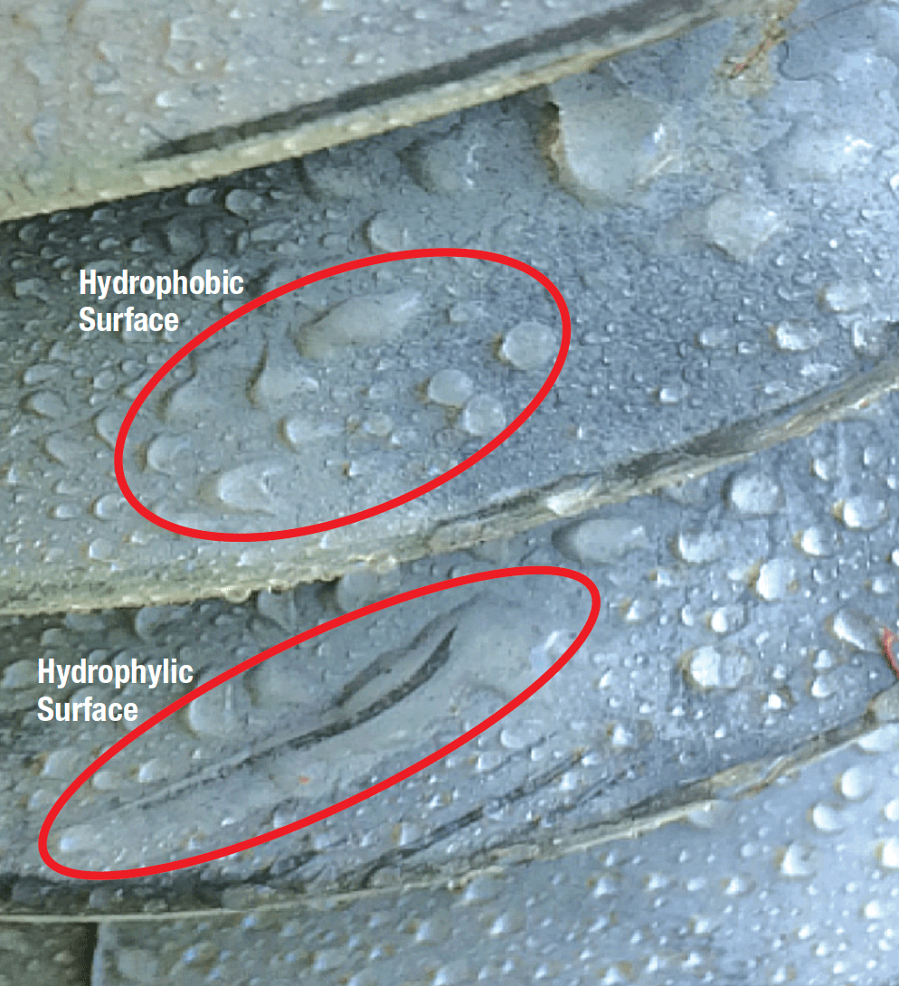
The importance of this parameter is still not fully understood and both surfaces work in the field. Porcelain is hydrophilic by nature and the arrester housing will easily last decades, perhaps centuries. It is also known that all polymer rubbers start out with hydrophobic surfaces but some become hydrophilic over time. Again, 30 years of field experience has shown that housings can still perform well even when their surface becomes hydrophilic. There is however one accepted difference between hydrophobic and hydrophilic surfaces, i.e. steady state power frequency loss. With a continuous, resistive path to ground along a hydrophilic surface, more current flows than on hydrophobic surfaces. This results in higher losses when the surface is wetted. Indeed, losses can add up to hundreds if not thousands of watts over the life of an arrester. Still, compared to losses from other equipment, arrester losses – even with a hydrophilic surface – are relatively low such that this parameter should not be a major issue.
a. Measuring External Leakage Current
On the topic of external leakage, this parameter can be used to determine when a station arrester is at the point where it may need to be cleaned. In contaminated regions, arrester counters with meters are often used to measure external leakage current and trigger cleaning events based on this value. Since surface leakage current will change with age, this practice may need to be studied to determine at what point it will be a true indicator of the need for cleaning.

b. Reducing External Leakage Current
i. Cleaning
There are two ways to reduce external leakage current on a wet arrester: the quicker is to clean it. In high ESDD zones, housings can be cleaned periodically to reduce external leakage current and lower risk of external flashover and/or internal partial discharge due to radial stresses. The same precautions should be used when cleaning arresters as when cleaning insulators and both porcelain and polymer-housed types can be cleaned.
ii. Application of Silicone Grease or Silicone Compound
This method of reducing surface leakage current on both porcelain and polymer-housed arresters has long been used in coastal locations and is effective in reducing risk of external flashover. In some cases, the material applied will age or peel over time and require another application.
Material Considerations
Porcelain-Housed Arresters
Porcelain of various types has been available for more than 150 years and has been used for insulators as well as spark gaps (described by Joseph Henry in his writings about surge protectors). This material evolved significantly over the decades and high strength alumina porcelain is now typically used for arrester housings. These housings are glazed on the outside and sometimes on the inside as well. The porcelain body is usually porous enough that it will transmit moisture over the long-term but, with high-density glaze, these housings have become impervious to water. Brown and grey glazed porcelain have the same properties except for color. Terminating these housings with metal caps and effective seals has always been and remains a major consideration in long-term performance.

Polymer-Housed Arresters
Introduction of polymer-housed arrester technology brought primarily two types of materials to the marketplace: the first was ethylene-propylene based rubber, referred to as EPR; the second was silicone rubber material, known as SR material. The greatest concern and question mark with these at time of their introduction was long-term performance. Many different tests were developed and adapted from the insulator world to estimate expected service life of these materials applied on arresters. The real test, however, has been some 30 years of field experience. While there have been a few arrester models where such housing materials did not perform, both EPR and SR types have on average shown excellent ageing characteristics. In those cases where housings did not perform, formulations were modified and subsequent designs remain in service today. It is still not clear for how much longer housing materials on arresters installed 30 years ago will continue to perform their multi-faceted function.
Radial Stresses
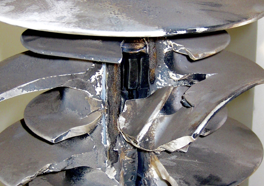
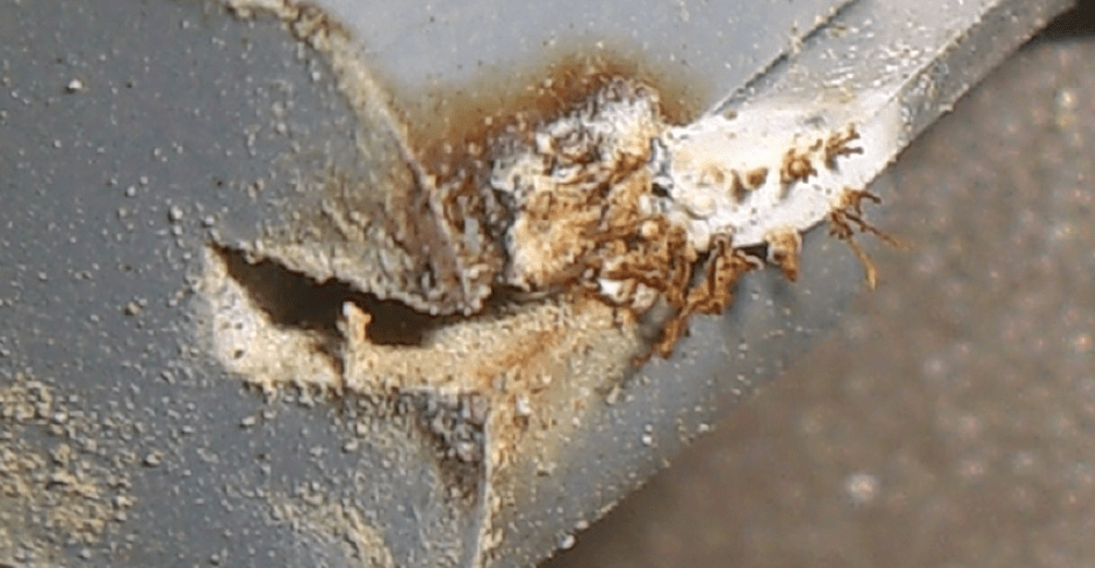
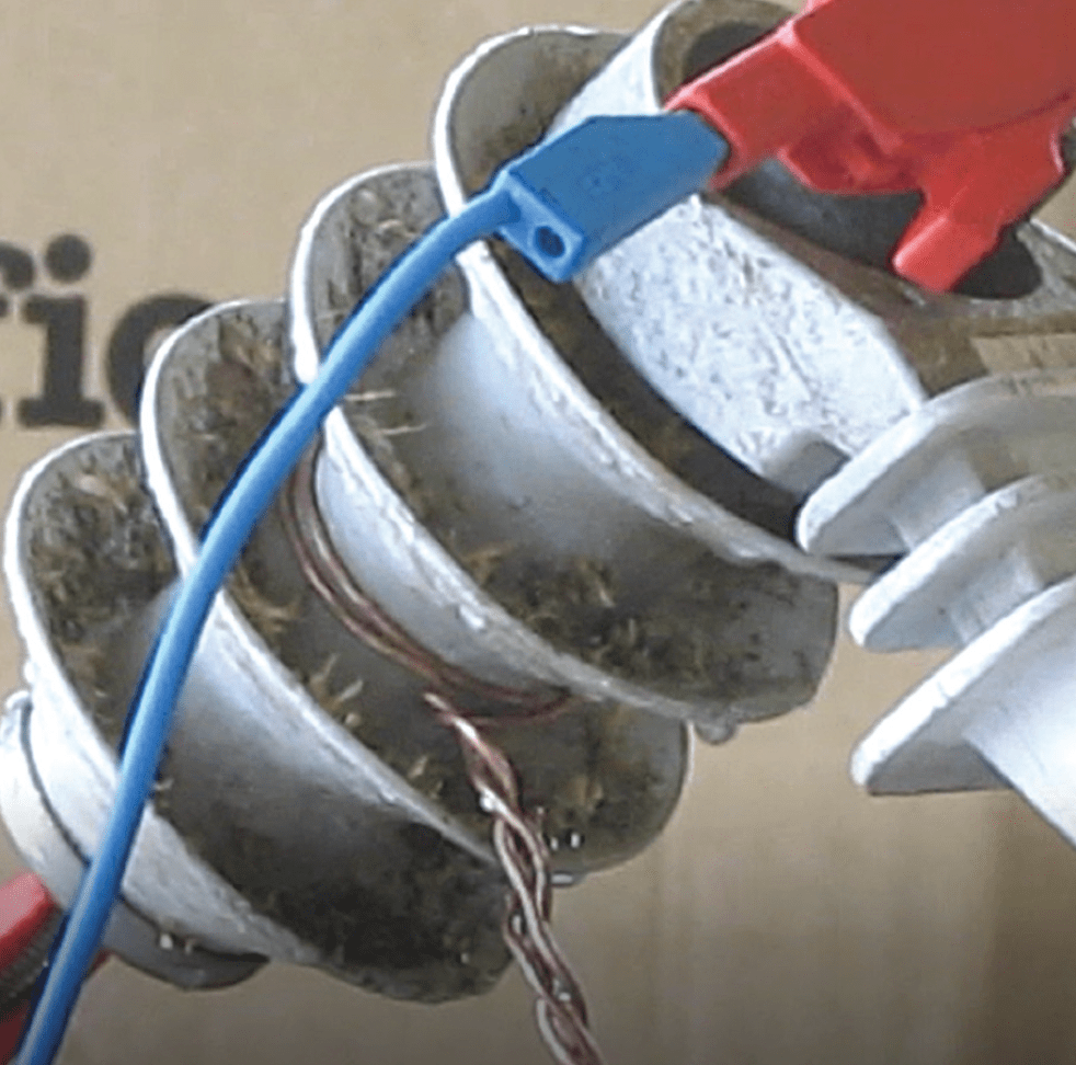
When the external surface of an arrester becomes wetted, voltage distribution along the outside is highly unpredictable. For example, there can be times when ground potential moves up or high voltage potential moves down. At the same time, the MOV disks inside the arrester maintain well-known steady voltage distribution. If this occurs, voltage differences between inside and outside can grow to levels that result in partial discharge of any air that is in the path of the radial stress. For porcelain-housed arresters and hollow-core polymeric arresters where large air volumes are present by design, such stress can result in internal damage and significant ageing of the arrester. It has always been accepted that this might occur but historical failure rates suggest this is at a level that will not lead to ageing of internal components. However, in highly contaminated environments, partial discharge can lead to internal flashover and complete arrester failure. Arrester housings with extra creepage distance or housings with hydrophobic surfaces that ensure only minimal leakage current have significant impact in preventing ageing or failure of internal components due to this issue. Fig. 6 shows ageing inside a porcelain-housed arrester from internal partial discharge.
Organic Growths on Housings
Users in many regions of the globe have reported that arrester housings can become covered with organic biological growths. There may well have been instances where such growths resulted in external flashover or internal partial discharge. But based on the limited numbers of failures reported under these circumstances, this is not believed to be a major cause of flashover or arrester failure. Growths, while not aesthetically pleasing, do not appear to change arrester performance in most cases. Fig. 7 shows an example of extreme organic growth that, when tested, was found not to affect housing flashover, wet or dry.

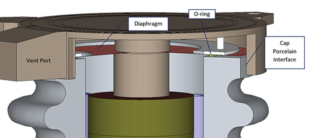
Sealing System Considerations
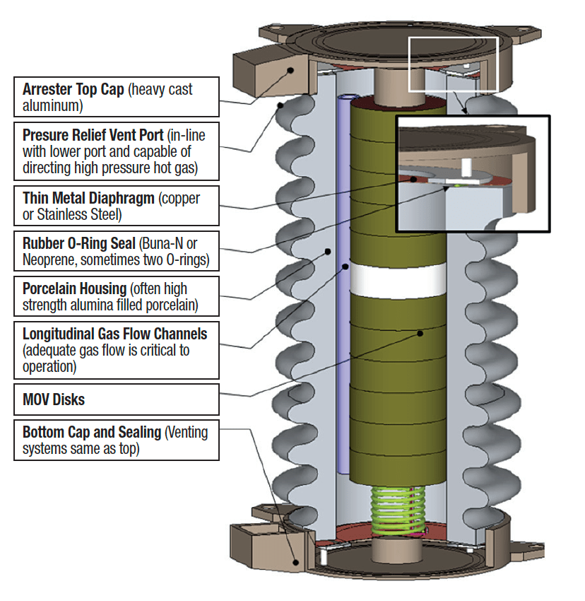
More or less the same types of sealing systems have been used for decades in both porcelain-housed and hollow-core polymer arrester designs and have shown to be effective. Of course, there are design variations but these are fundamentally similar (see Fig. 8). Common components in seals are the adhesive, metal and rubber O-rings. In early designs, solder may have been used in place of the O-ring for even more durable sealing. The biggest issue with the O-ring design is possible ageing of the rubber, which can over time lose its ability to apply pressure on the two surfaces between which the O-ring is compressed. If this happens, moisture can pass the seal and reach the inside of the arrester, causing internal failure in a short time.
The adhesive in the seal, by contrast, transfers mechanical forces from the housing/composite tube to the metal end caps. In the case of hollow core designs, this organic adhesive is similar to that used in insulators and has demonstrated a history of good performance. For porcelain housings, the adhesive is typically Portland cement or some variation of sulfur cement.
Rubber Permeability
All organic materials are somewhat permeable to gases. What this means for polymer-housed arresters is that, at some low rate, H2O molecules will find their way through the housing and, over time, humidity of the internal air volume will become the same as in the environment outside the arrester. For the hollow core polymer-housed arrester (Type 2), the epoxy/fiberglass tube has an extremely low water vapor transmission rate and will act as an effective vapor barrier. As a result, the rubber will saturate with moisture at a molecular level but the molecules will not migrate further into the arrester. For the polymer-housed arrester with rods or wraps (i.e. Type 3), moisture may or may not stop at some point and, over time, H2O molecules will enter the arrester. If the interior of the arrester does not contain large air chambers, this moisture does no harm. But if the interior has large air voids, water can condense during cooler temperatures, leading to internal tracking and eventual failure. For any polymer-housed arrester of this type, effective water vapor barriers need to be in place to avoid risk of long-term failure.
Failure Mode Considerations
If an arrester becomes overloaded, it will likely become a low impedance path to ground and allow thousands of amps of system AC current to flow through the unit. This AC current is referred to as system fault current and handling it during arrester overload is a significant task for the housing. For porcelain-housed arresters there has typically been two choices in these situations: either do nothing, as typical for distribution type arresters; or go to great lengths in design of end fixtures to allow rapid de-pressurization of the unit. The same venting end-caps used in porcelain-housed arresters are now also applied to polymer, hollow core designs. Their decades of use and development make them highly effective in preventing serious fragmentation failure. For polymer-housed arresters of design Type 3, gases formed in the arrester during a fault event are rapidly expelled at many points along the arrester. These multi-vent ports make ‘fragment-proof’ arresters a reality. Designing an arrester housing for safe failure mode is a tenuous but critical task.
Conclusions
Several considerations must be taken into account when designing a good arrester housing. These require a combination of electrical, mechanical, chemical, pneumatic and materials engineering skills. Designers tackling arrester housings will no doubt agree. For arrester users, understanding the principles behind selection of housing design allows them greater insight into what to expect from an arrester and which issues may need to be addressed.