Over the past decade, demand for longer lines and higher current capacities for HV power cables has required new methods of loss prevention. At the same time, ensuring high reliability of these lines is progressively more important. Together, these developments have sharply accelerated application of surge protection on underground cable networks.
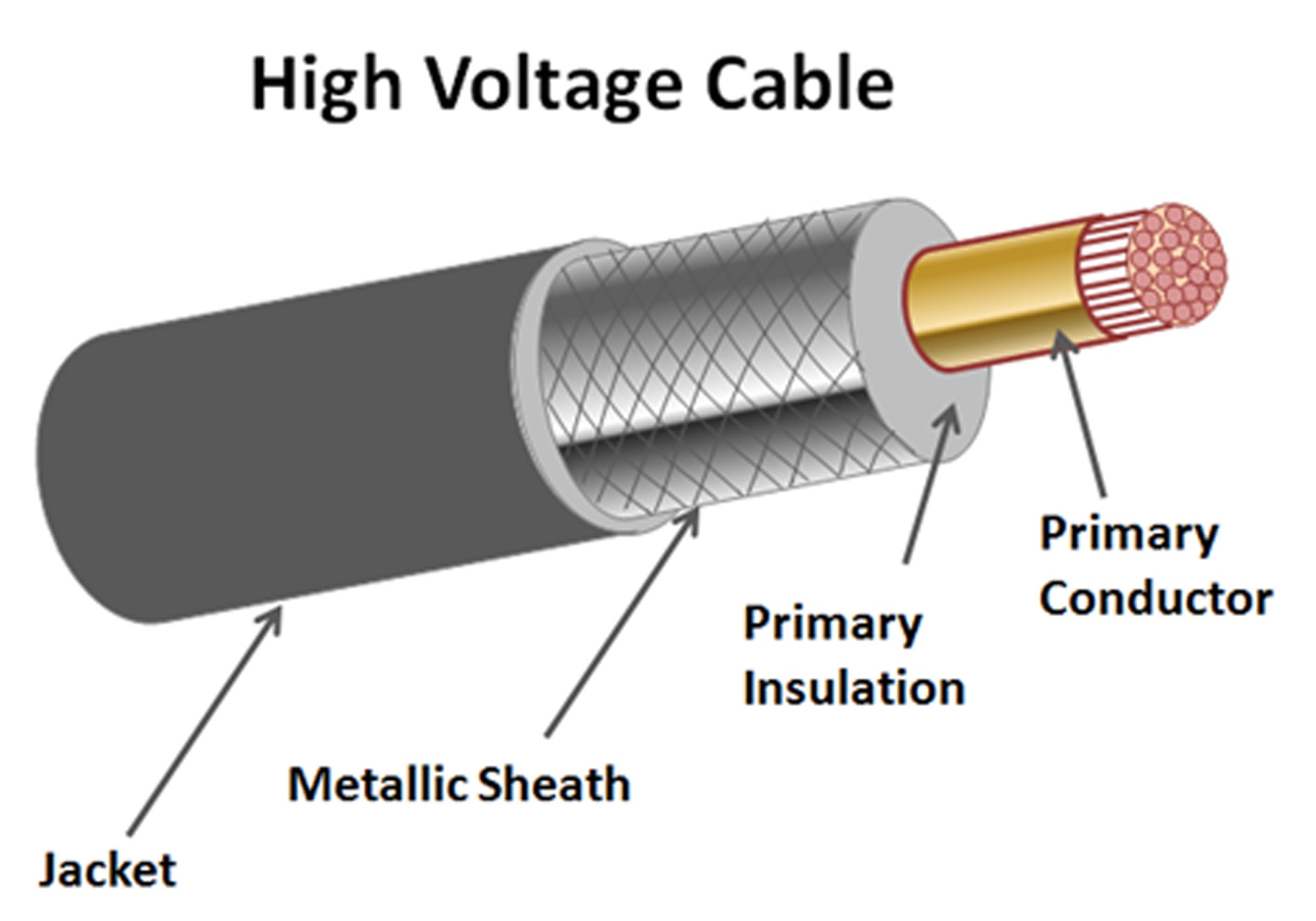
This edited past article, contributed to INMR by arrester expert Jonathan Woodworth, explained the surge protection scheme offered by sheath voltage limiters (SVLs) – devices intended to protect the cable jacket from electrical stresses during transient events. Since high voltage cables these days are available in an array of different types and designs, for the sake of simplicity the focus was on a single core HV cable with metallic sheath and polymeric outer jacket.


Introduction
Growth in installation of underground cables has focused more attention on some of their potentially negative environmental effects. Because cable is often installed with metallic sheaths, current is induced onto the sheath from the primary conductor and flows directly to earth, representing a 100% loss of energy. In the process it can also raise the temperature of the cable, which then becomes a limiting factor in the system’s overload capability.
A common means to reduce such losses is to segment the cable sheath (as in Fig. 2). However, if segmentation is used to interrupt induced sheath current, measures must also be taken to limit voltage induced on the sheath during transient events. Otherwise, the voltage differential between sheath and earth can exceed the cable jacket’s withstand, leading to puncture. This can become a point of moisture ingress, which can lead to long term dielectric and failure issues.
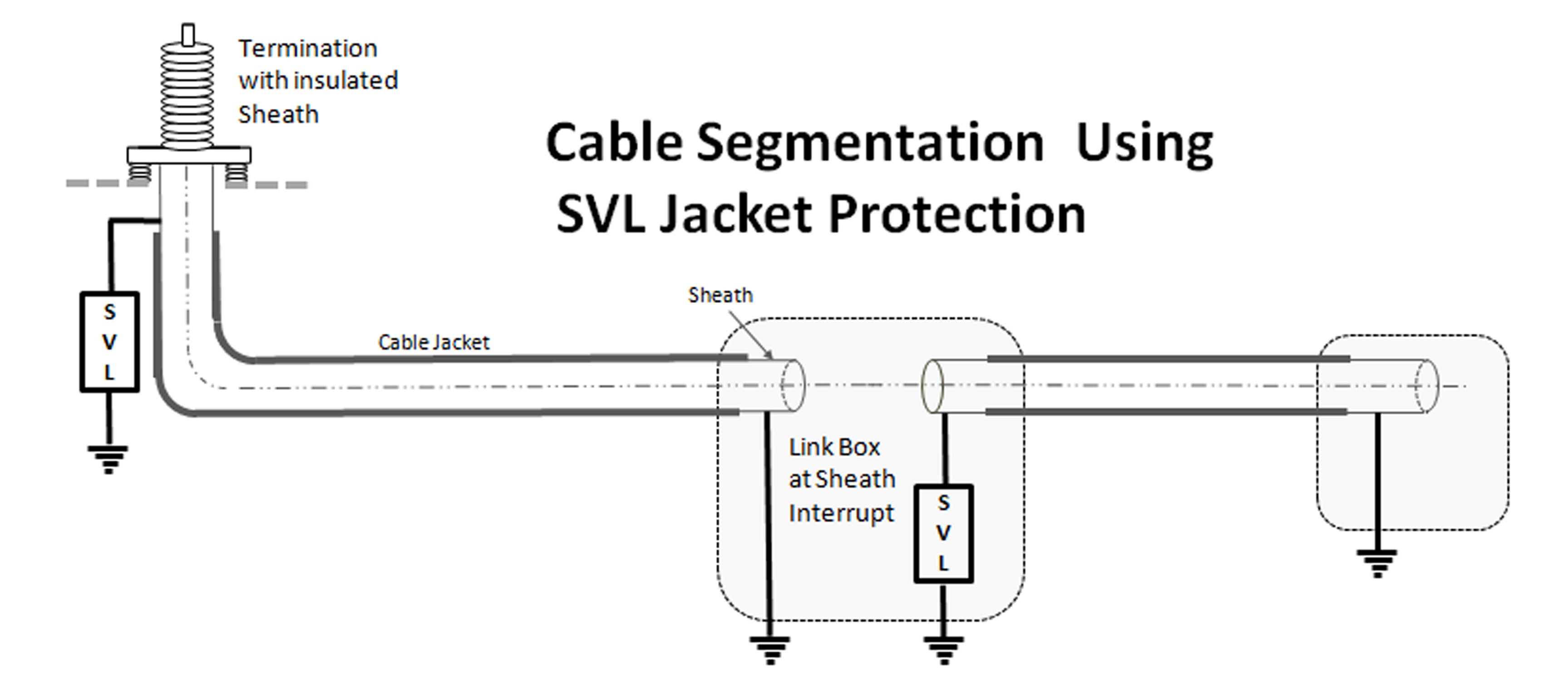
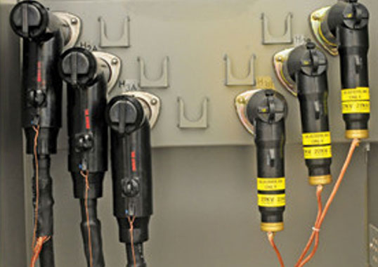
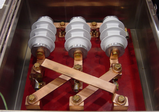
While a range of configurations is used to reduce losses in cable systems, (including cross-bonding of the sheaths and transposing phase conductors) segmentation along with surge protection of the cable jacket is considered the most effective. The link box in this case is a universally used sealed junction box placed either in manholes or cabinets and that accommodates surge protectors as well as a point to cross-bond the sheaths. Figure 4 shows a typical such link box setup that provides a location for the sheath voltage limiters as well as for cross bonding of the sheath. The phase conductors do not enter the link box, rather only the sheath or sheath extension.
The SVL
A sheath voltage limiter (SVL) is basically a surge arrester under a different terminology. It functions as an arrester and, in most cases, is in fact a re-labeled distribution arrester.
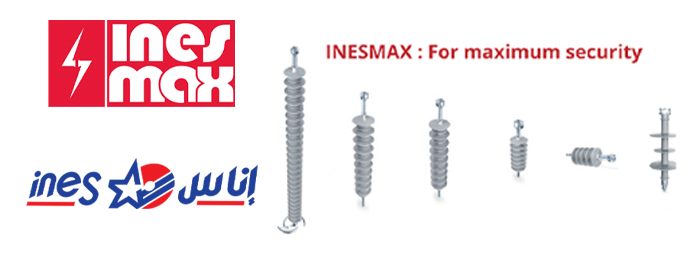
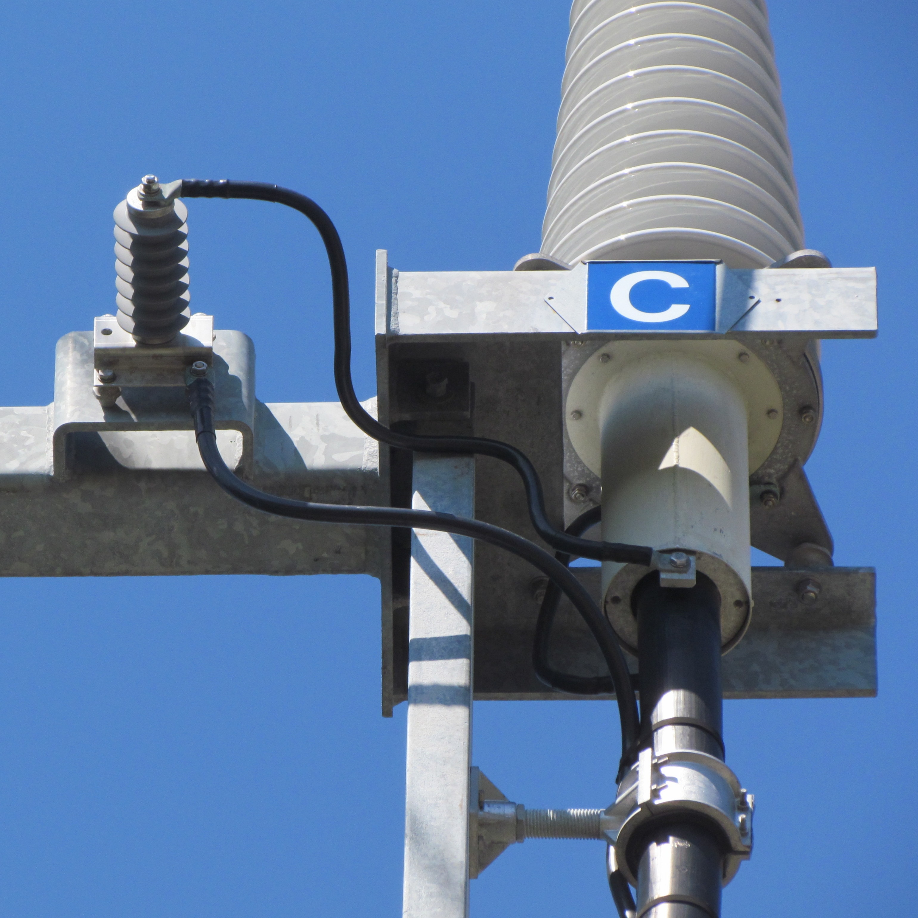
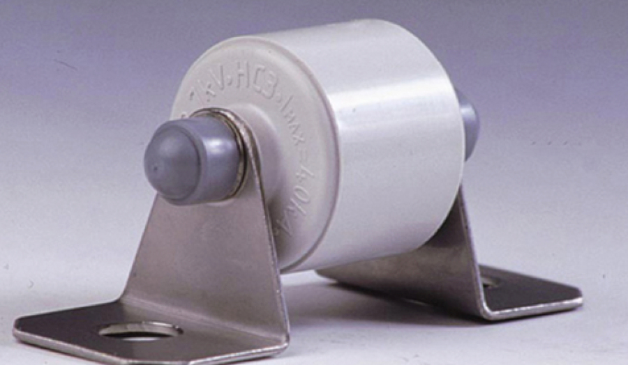
Two examples of sheath voltage limiters are shown in Figures 5 and 6. In Figure 5, the arrester has no sheds because this particular design is intended only for use in the dry environment of a link box. By contrast, the SVL model shown in Figure 6 has sheds similar to an arrester because it is intended for outdoor application.
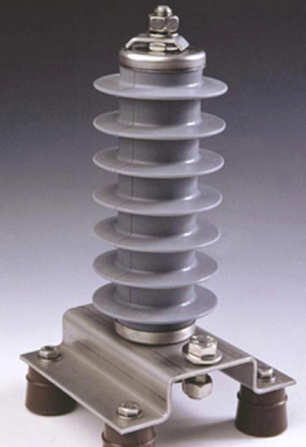
(MCOV) for use outdoors.
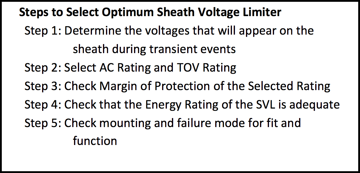
Selecting an SVL
As stated earlier, the main purpose of the sheath voltage limiter is to clamp or limit the voltage stress across the cable jacket. If the cable sheath is grounded at both ends, the voltage stress across the jacket is quite low during steady state and also relatively low during transients. However, if the cable is segmented to reduce losses or if there are link boxes along the cable at locations of transposition or cross-bonding, it is important to install the SVLs here to eliminate any risk of insulation breakdown of the cable jacket or link box.
There is no standard method prescribed by IEC or IEEE for selecting the optimum rating for cable sheath/jacket protection. The following method is therefore proposed based on discussion with cable suppliers, arrester suppliers and with the aid of transient modeling of the system to determine the effects of a surge during transients.
This analysis assumes sheath segmentation is a single point bond (earthed at one end of the sheath) and an open point at the other end.

Sheath Voltage from Power Frequency Sources
Sheath Voltage from Power Frequency Sources
Because the sheath of a cable is in such close proximity to the conductor, the voltage appearing on an open sheath can be substantial and is directly related to the current flowing through the phase conductor. This relationship applies during steady state as well as during faults.
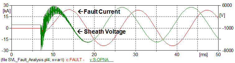
Figure 8 depicts an example where a 17 kA fault results in 3800 Vrms on the sheath. The most common rationale in selecting an arrester for protecting the sheath is to select an SVL with a turn-on level above the worst case induced power frequency voltage. This means the SVL does not need to dissipate any energy during a temporary overvoltage (TOV) caused by faults. For overhead arresters, this is generally not the rule and, in those cases, the arresters are sized to conduct current during the TOV but not enough to cause it to fail. The overhead sizing rationale utilizing an arrester’s TOV capability is not used for SVL selection unless it is necessary to achieve a better margin of protection.
Sheath Voltage Calculations
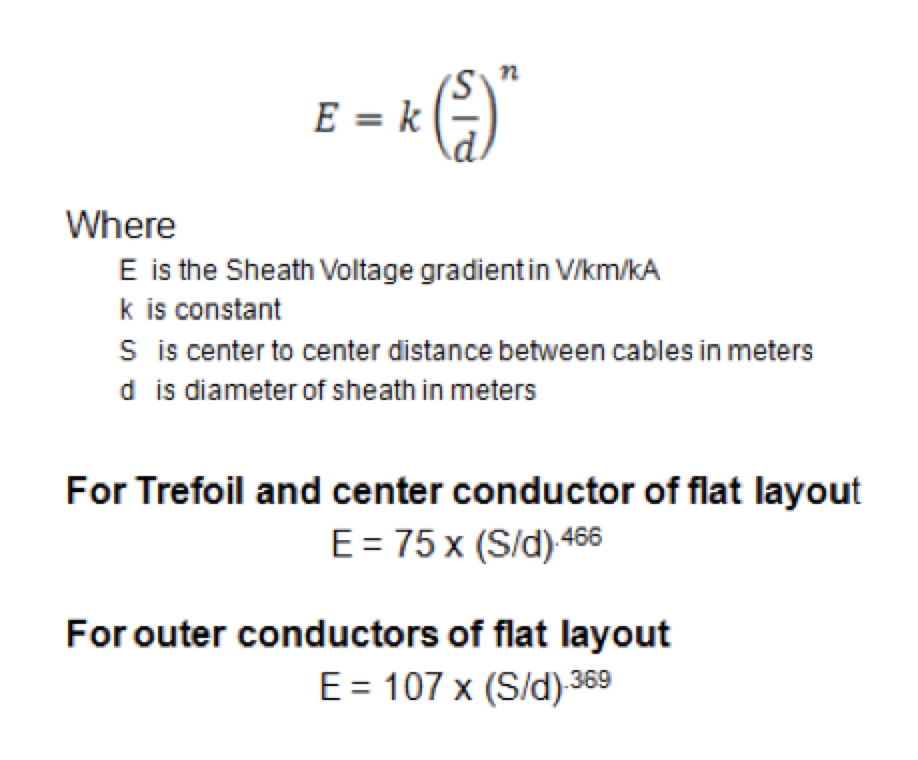
The steady state voltage gradient is the voltage that will appear along a 1 km length of sheath with 1000 amps flowing continuously and is a function of the configuration of the cable in the trench as well as its dimensions. There are two basic trench configurations: the trefoil, comprised of three cables that are positioned equidistant from one another such that their cross-section forms an equilateral triangle; and the flat configuration whereby all cables are laid such that they are in the same plane and the same distance from one another.
If the voltage gradient is not supplied by the cable manufacturer for the configuration used, it can be calculated using relevant equations and methods derived from IEEE 575 “Guide for Bonding Sheaths and Shields of Single-Conductor Power Cables Rated 5 to 500 kV”:
Once the voltage gradient is known for 1 km at 1000 A, the voltage that will appear at the open end of a segment during a fault event can also be calculated. It is important to determine this voltage level because the SVL voltage rating (Uc) needs to be set just higher so that the arrester does not conduct during a fault event. Should the arrester conduct in this instance, it would need a much higher energy handling capability than generally available for distribution type arresters. If it is found later in the sizing process that a lower level Uc is needed, a transient analysis will determine the SVL’s proper Uc and energy rating.
Assuming that the margin of protection will be adequate, then the Uc rating of the SVL will be greater than or equal to the voltage at the open point (Eopen), as follows:
Uc ≥ Eopen= voltage gradient x segment length x max. expected fault current
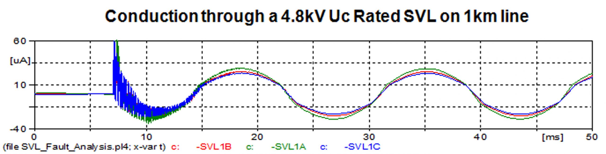
where voltage gradient is V/km/1000A, length is in km and fault current is expressed in kA. For example, if a voltage gradient on a particular system is 200V/km/kA and the line is 2 km long with a potential of 17.5 kA, then the minimum acceptable Uc rating for the SVL would be 7000 V. Note that if the line were only 1 km long, the SVL’s minimum Uc would be half that of the 2 km long line and could be a minimum of 3500 V.

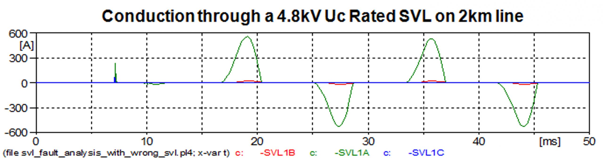
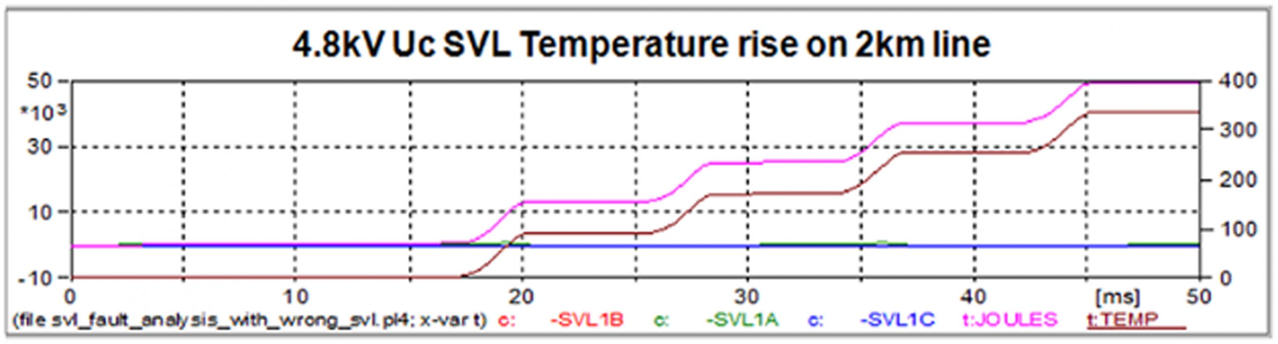
Figure 9 shows the current flow through an appropriately rated SVL on a 1 km line with the above-mentioned voltage gradient and fault current. It can be seen that only some microamps flow through the SVL, which is exactly what is desired. However if the same SVL is applied to a similar line of 2 km length, the current through the SVL would be significant (as in Figure 10) and the immediate temperature rise to failure is shown in Figure 11.
Therefore, when determining the proper Uc ratings for SVLs, one cannot select one rating for all link boxes unless the lengths of all segments are equal. Moreover, if the SVL is chosen correctly, it will not be required to absorb any significant level of energy during a system fault.
Protecting the Jacket from Switching Surge
The jacket and sheath interrupts are generally the weakest insulation in a HV power cable system. Figure 12 shows their withstand levels as per IEEE 575.
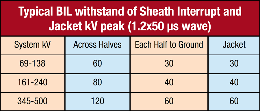
Switching surge impulse withstand of the sheath interrupt and jacket are assumed to be similar to other insulator types and are 83% of the lightning impulse withstand rating (BIL). When there is a switching surge event on the phase conductor of a cable, the current through it will induce a voltage on the sheath in the same way it does at steady state or during fault events, even though the wave shape is significantly different. Since the voltage and current on the conductor during a switching surge are not sinusoidal or even a simple impulse (see Figure 13), it is not possible to accurately predict the resulting voltage and current on the sheath.
The only ways to accurately determine the actual voltage and current on the sheath are through transient simulations or real field tests. Since tests are not practical, transient simulations are really the only option and some useful rules of thumb have emerged from running such simulations:
1. If the SVL is selected to ride through a fault event with minimal to no serious conduction, then the switching surge energy withstand capability of a 10 kA rated distribution type arrester is adequate. If the SVL is not dimensioned to ride through the fault, then station class arresters may be needed.
2. If the 1000 A switching surge residual voltage is not available, then the 1.5 kA 8/20 lightning impulse residual voltage can be used for the margin of protection calculation.
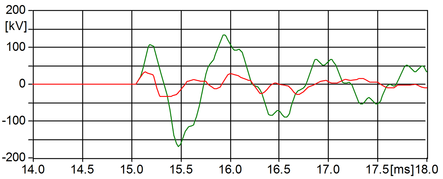
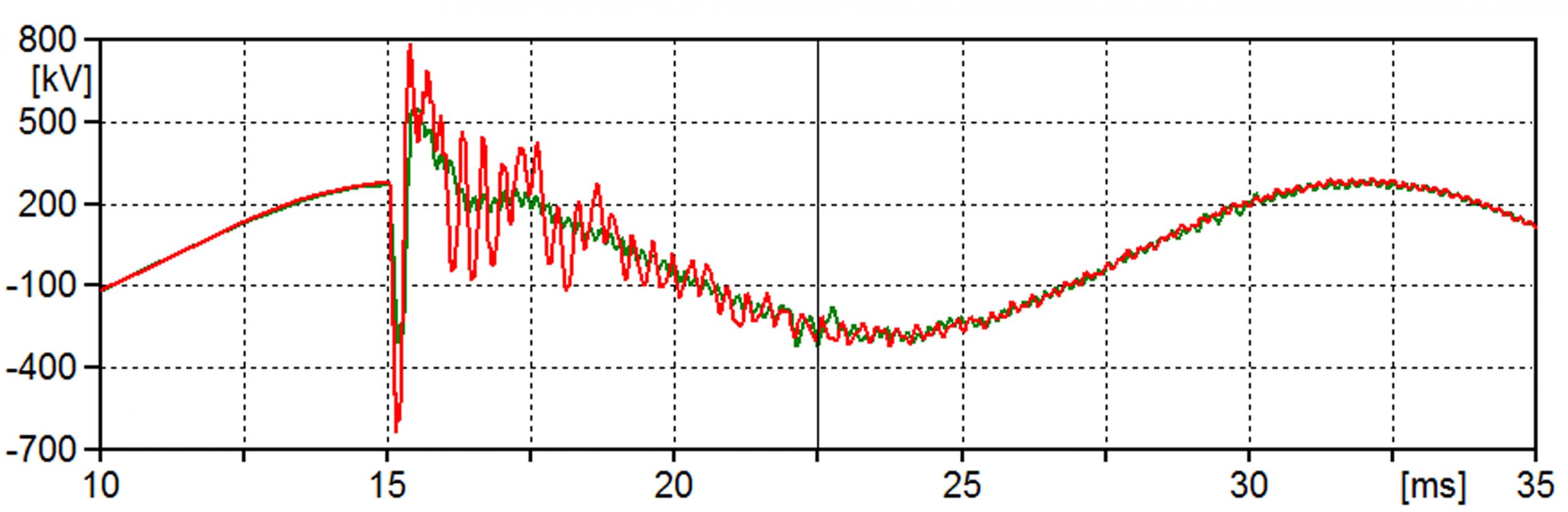
In the case study used to create Figure 14, the switching surge voltage on the sheath without SVL protection would rise to greater than 100 kV. According to Figure 12, this is more than 40 kV above what the jacket or interrupt insulation can withstand, representing certain failure of the cable jacket. In this case, with an SVL of 9.6 kV Uc, the voltage on the sheath is limited to a maximum of 33 kV.
To calculate margin of protection during a switching surge, it is recommended that the 1000 A switching surge residual voltage be used. Since switching surge residual voltage is not a mandated test for distribution type arresters, the 1000 A residual voltage may not be available. In this case, a reasonable substitute for the switching surge voltage is the 8×20 residual voltage at 1.5 kA. For the 9.6 kV SVL used in the above study, the V1000=1000 A 30/75µs residual voltage is 28.4 kV.
From Figure 12, it can be seen that the BIL withstand level of the jacket for a 345 kV line is 60 kV. This means that the switching surge margin of protection (MP2) for this case is: MP2=([( BIL x .83 )/V1000 ]-1) x 100 = 111%

Protecting the Jacket from Lightning Surge
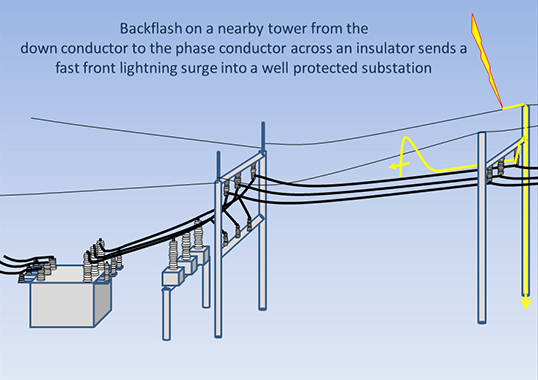
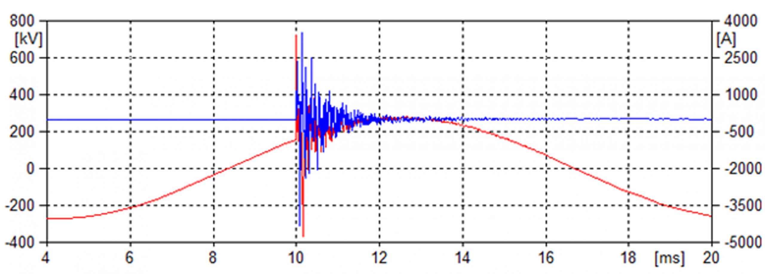
When lightning strikes an overhead line before the transition pole, the surge is clamped by the arrester that is universally mounted at this location and most of the surge current is diverted to earth. However, a surge voltage of significant magnitude can travel into the cable with a moderate level of current as well. Figure 15, for example, depicts the voltage and current entering a 345 kV cable given a 100 kA lightning strike a few spans away.
Calculating margin of protection (MP1) for lightning is very similar to what is done in the case of switching surges. Here, 10 kA is used for the coordinating current and the full BIL is used for the withstand of the jacket and interrupt insulation. Using the same type of SVL as above for the switching surge calculation, the residual voltage at 10 kA is 35 kV and cable BIL is 60 kV. Therefore, MP1=([BIL/V1000 ]-1)x100 = 71%. Again, a 9.6 kV Uc SVL will provide adequate insulation protection for the cable jacket.