Service experience is key when it comes to evaluating the level of maturity and reliability of any electro-technical component. While there is typically a great deal of attention devoted to collecting such field experience during the initial years of any new technology, this is more challenging once products enter mass production. As a result, real service experience risks being replaced by rumors and perceptions, even if inaccurate.
A group of 8 European power companies carried out research intended to benchmark performance of composite insulators. The project included collecting service experience as well as comprehensive testing of insulators, both from storage depots and removed from service. The companies supporting this project included 50Hertz (Germany), Amprion (Germany), APG (Austria), E.ON (Germany), Fingrid (Finland), RTE (France), Statnett (Norway), and Svenska kraftnät (Sweden).
Collection of service experience within this project’s framework formed the basis for this edited contribution to INMR by Dr. Igor Gutman of the Independent Insulation Group (I2G), who coordinated the research. Primary interest was on overhead line insulators but these and substation insulators were analyzed separately because the two arrived in service at different periods. As such, their volumes and experience might be different.
Information on service experience with composite insulators has been comparatively scarce. Five CIGRE-inspired reviews are known to have taken place (the last still not officially published), but the information collected was limited. The main outputs included:
• Number of insulators installed;
• Maximum service period;
• Reliability;
• Typical reason for installation;
• Typical failure modes.
This first CIGRE survey in 1990 summarized service experience of composite line insulators at voltages higher than 100 kV, including suspension, tension and line post insulators. The total number installed was estimated as 140,000, and the volume of service experience (number of insulators times number of years) was 831,000. Thus, average service period was 6 years. Vandalism and handling were the main reasons for their application followed by pollution performance.
The insulator component that failed most often was the housing, explained by degradation of the material as was typical for first generation composite insulators. This was followed by failure at the core/housing interface. Reliability of composite insulators was estimated at 11×10-4 per year – an estimation acknowledged to be unrealistically low due to the definition of failure used in the questionnaire. Utilities were asked to define failure as “any condition that led to the removal of insulators from a line”. For example, one utility installed a batch of 350 insulators of the same type and after a few years in service three insulators broke while others showed signs of degradation. Although the remaining insulators still appeared sound, the utility nonetheless decided to remove all 350 and thus reported 350 failures even though only 3 had failed in reality. Considering this, actual reliability was likely 10 to 100 times higher, i.e., 10-4 to 10-5 per year.
The second CIGRE survey was conducted and published in 2000. Again, the survey looked at insulators for voltage levels higher than 100 kV, including suspension, tension, line post insulators and interphase spacers. Total number of insulators installed was estimated at 700,000 and volume of service experience was 4,679,000. Thus, average service period was 7 years.
Separate data from utilities in the United States were included in this survey and provided an average service period of from 14 to 15 years. Again, vandalism and ease of handling were the dominant reasons for their application, followed by use in upgrade/compaction projects, polluted service areas and price. The prevailing failed component now was the core, which might indicate brittle fracture, followed by the core/housing interface. This survey used a different definition of failure, i.e. “an insulator that could not sustain the system voltage or mechanical load”. This is the definition used now. Average reliability of composite insulators was estimated at 10-4 per year.
The third CIGRE-driven estimation of service experience for line insulators was presented in 2011 in a chapter included in a Technical Brochure (TB). This data was based mainly on a CIGRE survey together with more recent data provided by EPRI. The prevailing failure modes identified were brittle fracture and flashunder. This TB estimated reliability in the range 10-4 to 10-5 per year and considered mechanical failures to be the dominant failure mode. It should be noted that whereas data for conventional ceramic insulators refer to a consolidated technology representing about 100 years of experience, data for composite insulators included failures associated mainly with the first and second generations of this technology. As such, expected failure rates of presently available composite insulators should be much lower.
The fourth CIGRE review of service experience of line insulators involved WG B2.57 and was finished in 2021. The first draft of the TB did not offer any new information on service experience.
This first and the last items mentioned above in the CIGRE-driven survey on composite hollow core apparatus insulators in 2011 were included in the TB. Application of polymeric housings started on an industrial scale only in the early 1980s. Since then, the total quantity reached about half a million in the range 145 kV and above, based on data from 2006. Estimated market volume at the time was more than 50,000 insulators/year. If directly-moulded apparatus housings (e.g. surge arresters, cable terminations and bushings) at voltage levels above 60 kV are also considered, there would probably be one million units in service. Experience collected by this WG was limited but positive, with only minor degradation reported in a few cases.

Questionnaire & Response
Analysis of existing data on service experience led to the conclusion that such information was relatively scarce. A specialized questionnaire was therefore created and distributed to reflect the specific interests of the utilities participating in this project.
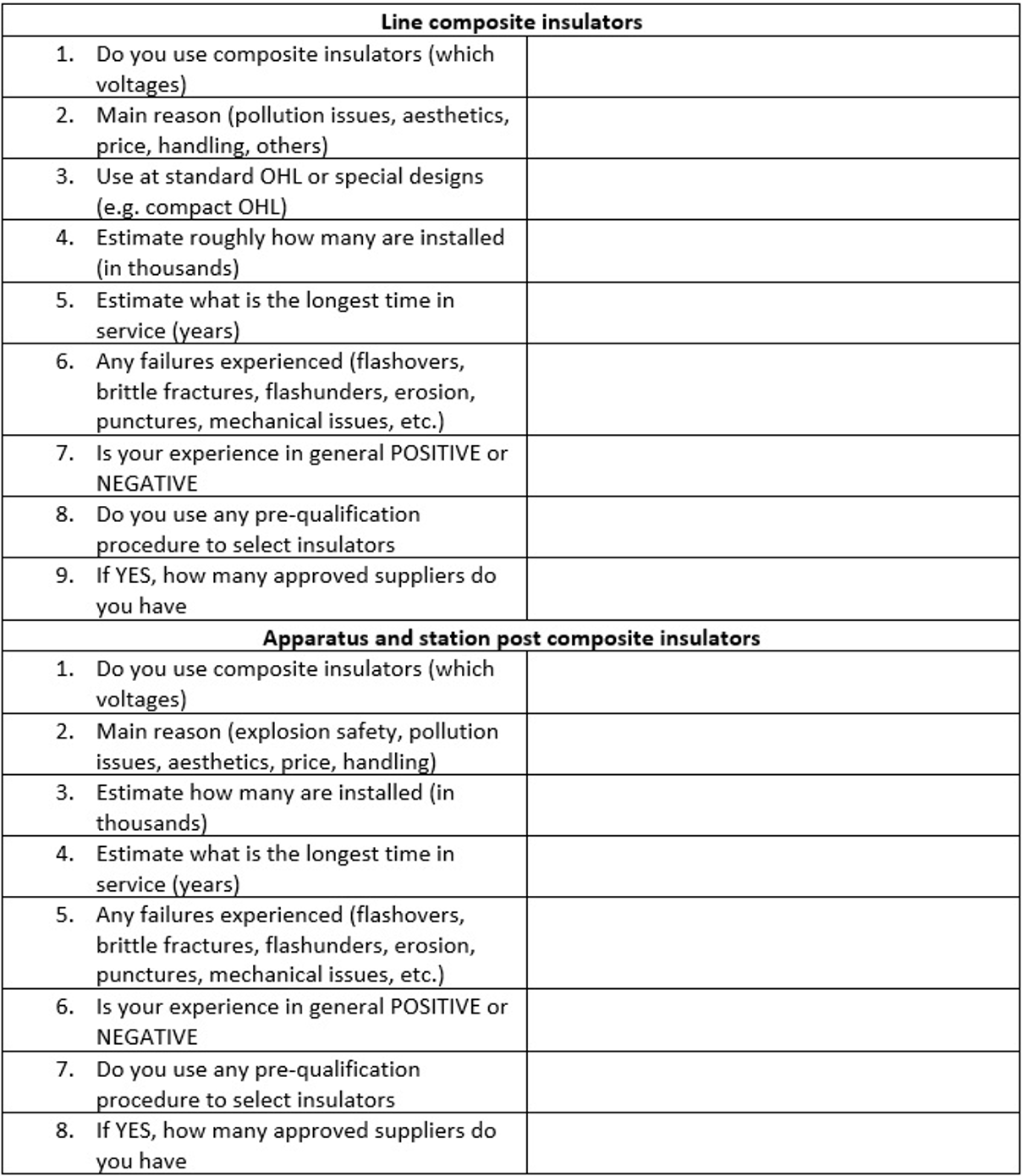
Fig. 1 shows an example of the questionnaire. A slightly more detailed questionnaire was also created and distributed to those utilities willing to contribute more data. These questionnaires were created in collaboration with all participants and the key issues to consider included:
• Compressed questionnaires (maximum 10-15 questions). Otherwise, they would never be answered.
• To be sent only to utilities where the project participants had contacts. Otherwise, probability to get a response would be low.
The questionnaires were distributed to 99 different companies and 53 answers were obtained providing a response rate of 54%. Only one of these 53 companies did not use composite insulators.
Unfortunately, not all large users of composite insulators on a country by country basis responded. Transmission voltage level in this study was defined as ≥110 kV.
Overhead Line Insulators
Total reported overhead line insulators installed at transmission voltages was estimated as 1.9 million while the total number of insulators installed at distribution voltages was estimated at 6.7 million. Thus, a combined total of 8.6 million units. This rather large number represented about 25% of the worldwide population, estimated to be between 30 and 40 million units based on discussions with international experts. Also, the upper limit for total number of composite insulators installed worldwide was verified during interviews with manufacturers.
Application of composite insulators is clearly commonplace with 98% of responding utilities using them. Insulators are used in standard as well as special designs of OHL (i.e., I- and V-strings; interphase spacers, insulated cross-arms, jumper supports and line posts).
Substation Insulators
Experience with some 260,000 composite substation insulators was reported. The total population of such insulators installed worldwide is thought to be between 2 and 3 million. Selection of composite insulators in this application is also common, with 92% of responding utilities using them. These insulators are used in a range of different apparatus, e.g. arresters, instrument transformers, circuit breakers, bushings) and also as station posts.

Maximum Duration in Service
Overhead Line Insulators
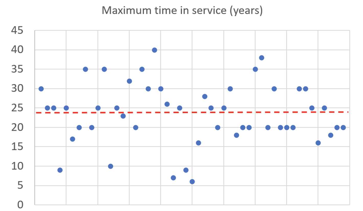
Maximum time in service was found to be similar for transmission and distribution voltage classes. Fig. 2 presents the data for both. Average maximum time was 24 years while maximum time was 40 years (i.e. still in service). There was also anecdotal data that several composite line insulators still operating in the Netherlands and Germany have been installed for more than 40 years.
Substation Insulators
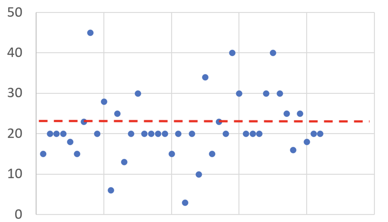
Average time in service for substation insulators was 22 years and maximum time was 45 years. Fig. 3 summarizes these results.
Service Experience
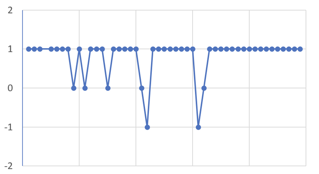
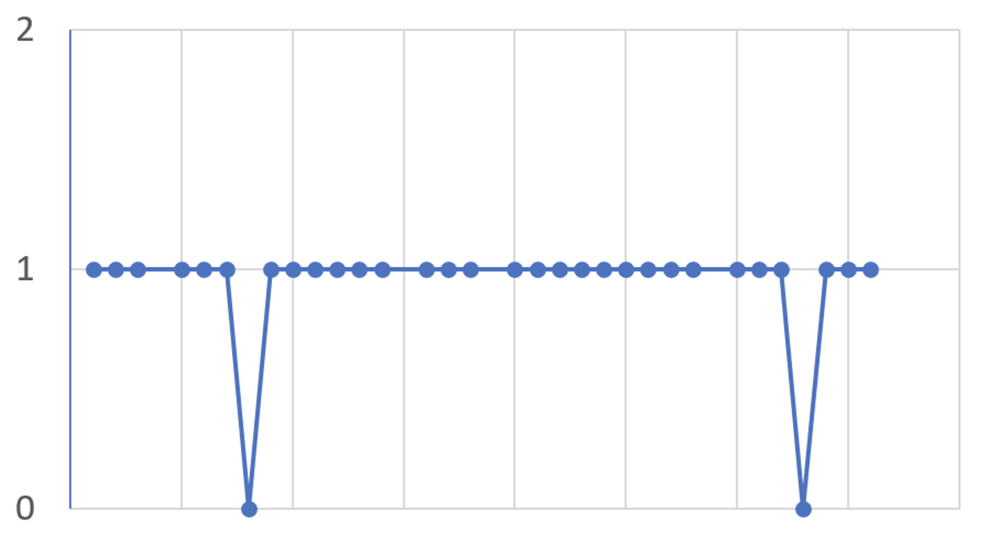
Power companies were asked how they evaluate the overall experience with composite insulators. Three levels of answers, created by respondent companies, i.e., positive, mixed or negative were obtained for overhead line insulators and were marked as “+1”, “0” and “-1” respectively. This information is summarized in Fig. 4.
In the case of substation insulators, only two levels of answers were obtained, i.e., positive and neutral, comparable with “mixed” for line insulators. “Neutral” was considered as “smoother”, because it was built mostly on expectations for additional service. These levels were marked as “+1” and “0” respectively (see Fig. 5).
Overhead Line Insulators
Fig. 4 summarizes combined assessed service experience by transmission and distribution companies. For the majority, experience was positive (86%) compared to 4% negative and 10% mixed.
It is interesting to note that those companies who responded as “mixed” or “negative” did not use any pre-qualification procedures in their selection of insulators. Such procedures can be significantly different, from choosing among only a few qualified supplies to analyzing test reports and comparing these to the technical specifications created by the power companies. For example, 72% of utilities that considered that they have had positive experience with composite line insulators regularly used pre-qualification procedures or tenders with follow-up analysis of test reports versus only 28% that did not. It therefore seems worthwhile to apply such pre-qualification procedures.
Substation Insulators
Experience is shown in Fig. 5. For the majority, experience has been positive (94%), with the rest (6%) defined as neutral. By contrast to experience with line insulators, only 25% of those utilities that considered their experience with composite substation insulators as positive were applying pre-qualification procedures.
Reasons for Application
Overhead Line Insulators
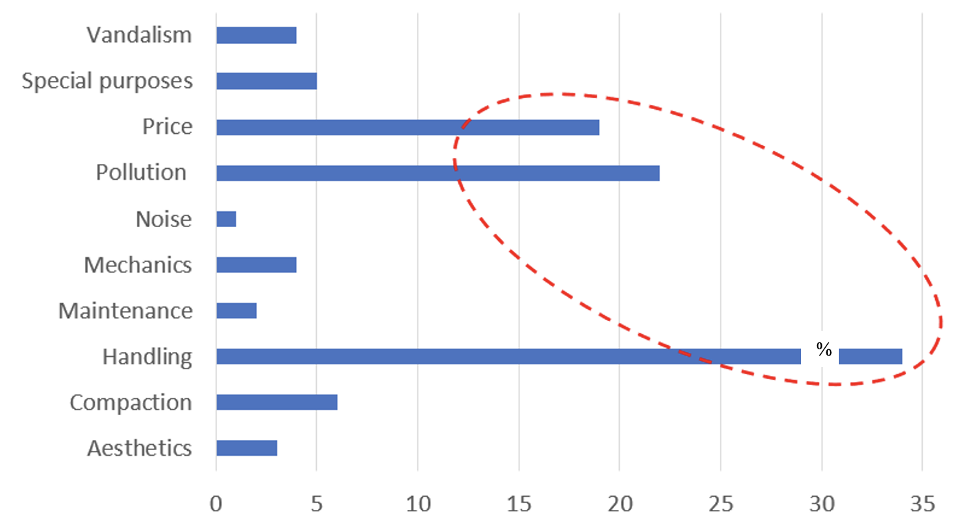
The reasons why utilities chose to install composite insulators were left open for them to define and are summarized in Fig. 6. This part of the analysis combined transmission and distribution voltage levels. For each responding utility, one point was given for every specific reason mentioned. Ease of handling was the dominant reason, whereas the traditional reason, i.e. improving pollution performance, came next, followed by price.
Substation Insulators
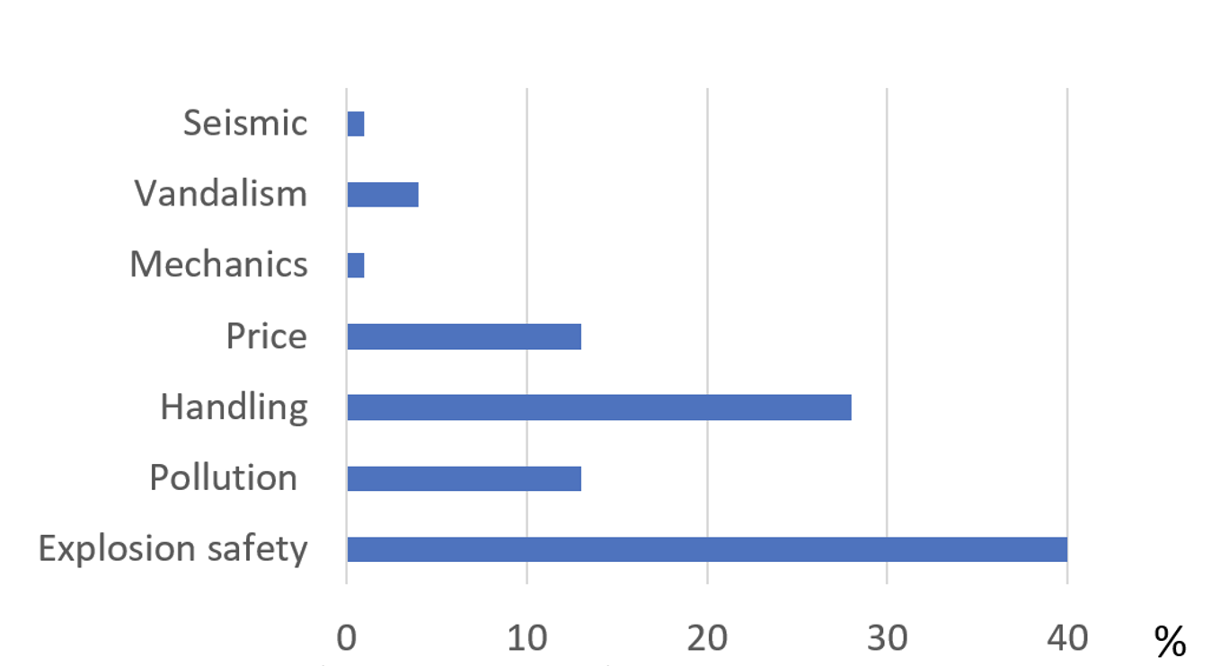
Fig. 7 summarizes why utilities choose to install composite insulators at substations. The reasons are again created by the power companies questioned and there are fewer than was the case for overhead line insulators. Not surprisingly, safety against explosive failure was by far dominant reason, while easier handling was the second.
Causes of Failure
Overhead Line Insulators
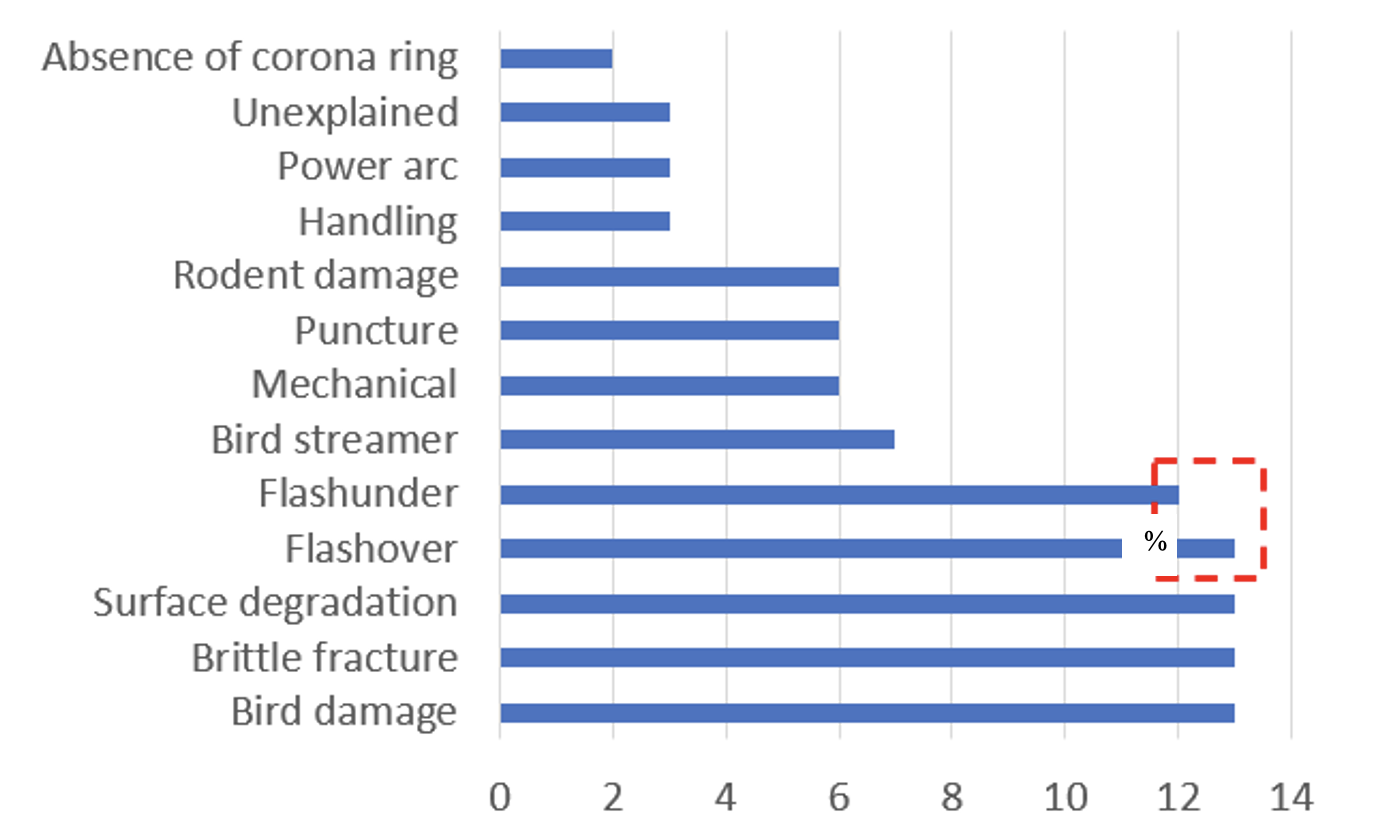
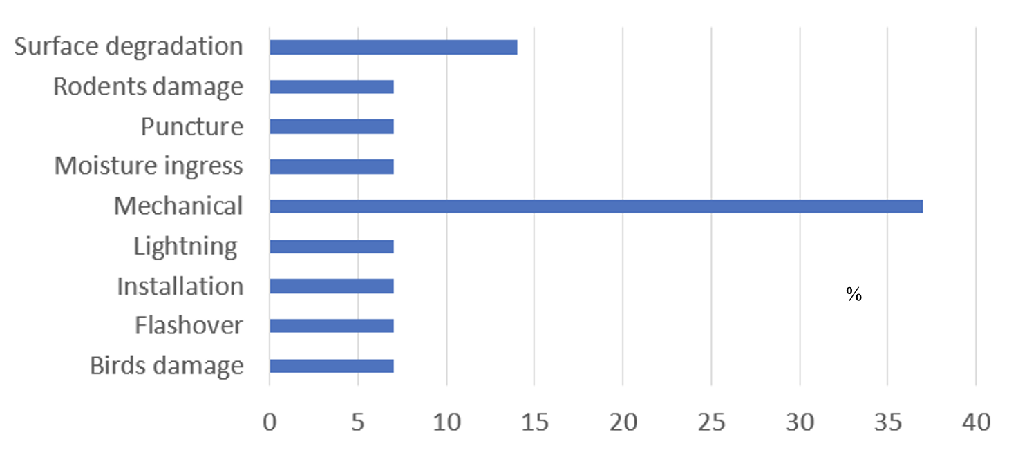
Fig. 8 summarizes causes of failure or failure modes of composite line insulators. Again, analysis of the replies included both transmission and distribution voltage levels. Five types of failure dominated: flashunder, flashover, surface degradation, brittle fracture and damage caused by bird pecking.
In regard to surface degradation (which combines erosion, cracking, etc.), it might be that a utility observing this type of degradation would decide to replace insulators even though the damage was not critical. Thus, it was proposed not to consider this failure mode in the analysis. It was interesting to note that flashover was mentioned among the most common type of failure, especially given that some “experts” have claimed that it is rare if not impossible for composite insulators to flashover in the classical pollution dry-band mode known for ceramic insulators.
It is therefore likely that some utility or service provider staff may not have been able to recognize the difference between ‘flashover’ (i.e. an external breakdown along the surface) and ‘flashunder’ (i.e. an internal breakdown typically in the interface between core and housing). If this is indeed true, the flashunder failure mode was dominant and part of the ‘flashovers’ needed to be added to the cases of ‘flashunder’. In spite of this, number of failures reported would still be low because, as mentioned above, 86% of responding utilities considered their service experience as positive. However, fewer than 20% of utilities were able to present their exact number of failures.
One difficult question was which generation of composite insulators were actually represented in the failures being reported. The questionnaire summarized all data collected, thus conservatively combining experience for all generations of these insulators, presently assumed to be four to five. Actual situations in service are illustrated by examples of comments received from utilities that had used composite insulators for many years:
1. “On one OHL the degradation of specific HTV silicone rubber led to a change of the mechanical properties (brittleness when mechanically stressed) due to a chemical reaction with acids and UV”;
2. “For the current generation issues are very rare and are basically flashovers due to bird-streaming”;
3. “Since we only have the third generation of composite insulators in our network, we have not experienced any failures”;
4. “Flashovers were experienced only for one supplier”;
5. “We observed issues with 20 – 25 years first generation EDPM insulators in the late 80s and early 90s with loss of hydrophobicity and tracking/erosion. But more recent supply of silicone insulators seems to be OK”;
6. “Expected asset life of composite insulators is 40 years; in the heavy contaminated environment near the coast, we replaced a particular brand of composite insulators after 13 years in service after two brittle fracture failures”.

Substation Insulators
Fig. 9 summarizes causes of failure of composite substation insulators. Mechanical issues were the dominant failure mode and it was assumed that these related mostly to station post insulators. Normally, only limited surface degradation was observed on apparatus insulators and it was often a subjective decision by the utility whether or not to replace such insulators.
Reliability
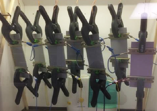
Attempting to calculate reliability in terms of number of failed units per year was complicated. This was because service experience, in terms of aggregate number of insulators installed multiplied by number of years in service should be known, as are the exact number of failures. Thus, in cases where no failures were reported, failure rate was nonetheless assumed to be one failure over the whole service period. Otherwise, aggregate volume of installed insulators was estimated by multiplying 50% of the maximum time in service by number of installed units, since only maximum service time was available.
Overhead Line Insulators
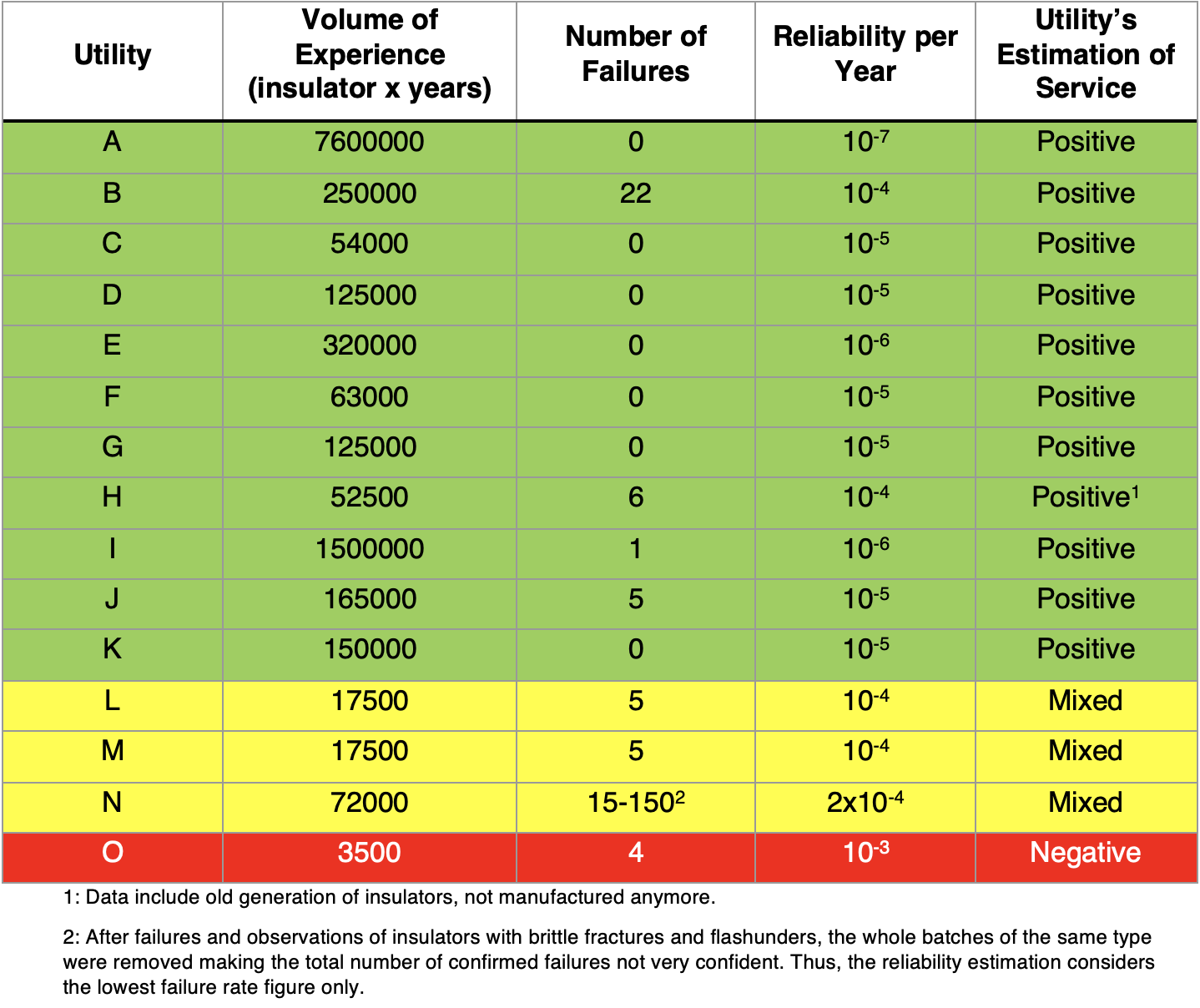
Table 1 presents such an estimation based on limited data from 15 utilities that were used to assess reliability. For visualization purposes, the answers from these utilities were arranged according to a traffic light principle, as GREEN (positive), YELLOW (mixed) and RED (negative). Based on this, the following conclusions were drawn:
• ‘Positive’ experience with composite insulators typically relates to an annual failure rate of 10-5 or less;
• ‘Mixed’ experience typically relates to an annual failure rate of 10-4;
• ‘Negative’ experience typically relates to an annual failure rate of 10-3;
• Average annual failure rate for all data collected in Table 1 was 10-5.
Substation Insulators
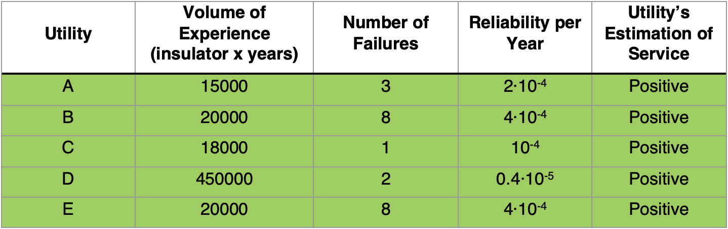
Data on failure rates of composite substation insulators is limited because of their relatively short service time compared with line insulators and also because most have operated without failures. Table 2 presents some information for 5 utilities that reported exact number of failures. Aggregate service time of installed insulators was (as for line insulators) taken as half the maximum time in service. Based on this, ‘positive’ experience expressed by a utility typically corresponded to a failure rate of between 10-4 and 10-5. It can be assumed that, with increasing service experience, failure rate will become lower, as demonstrated by the experience of utility D. Given a greater share of new generation composite insulators entering service, reliability would be higher, approaching 10-5 per year.
Use of Grading/Corona Rings
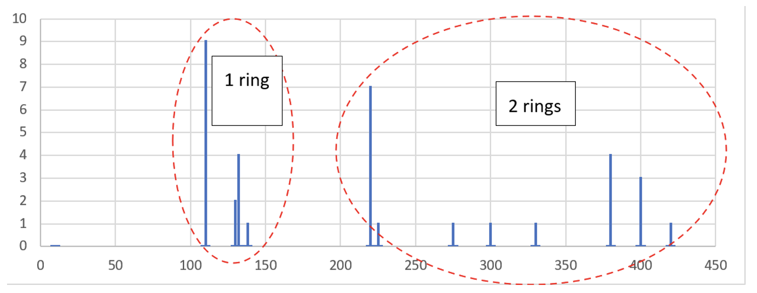
Fig. 9 analyzes the response from utilities that answered the question about application of grading rings. No grading devices were being used for distribution classes (i.e. below 110 kV). For transmission class insulators, general practice has been to use one grading ring (or sometimes only arcing horns) at the HV fitting starting from 110-132 kV and two grading rings (one at each end) starting from 220-275 kV.
Summary
Overhead Line Insulators
This project collected service experience linked to the operation of about 9 million composite insulators installed at transmission and distribution voltage levels. Information was collected using a questionnaire that received responses from about 50 utilities. Average time in service was 24 years (with a maximum of 40 years). Thus, the technology is considered as mature. These insulators were estimated to represent about 25% of the total population worldwide.
Replies received to the main questions formulated by participants in this project, can be summarized as follows:
• Application of composite insulators has become commonplace (confirmed by 98% of answers);
• Insulators are used on standard OHL and in special designs (I- and V-strings; interphase spacers, insulated cross-arms, jumper supports and line posts);
• The dominant reason for application is ease of handling (35%);
• Present service experience is considered as positive, as confirmed by 86% of replies. A large part of those utilities with positive service experience used pre-qualification procedures while utilities with negative or mixed experience typically did not use such procedures. Thus, it seems worthwhile to apply pre-qualification procedures;
• Types of insulator failure experienced were defined by the utilities on their own and not standardized. Therefore, it would be more correct to define them as “observations”. Five dominant types of failure were mentioned: surface degradation, flashunder, flashover, brittle fracture and bird damage from pecking. First commenting surface degradation (combining erosion, cracking, etc.), it might be that a utility observing this type of degradation decided to replace insulators, although this damage was not critical. Thus, it was proposed not to consider this failure type in further evaluation. Flashover is an interesting response because many CIGRE/IEC experts do not believe that classic pollution-driven flashover can take place on composite insulators. Even if it is believed that some ‘flashovers’ were actually ‘flashunders’, some classical surface flashovers should also have occurred. Assuming that a part of ‘flashovers’ really belonged to ‘flashunders’, this would become the single most dominant reason for failure. Subsequently, the ranking might be:
1. flashunder,
2. brittle fracture,
3. flashover, and
4. bird damage (this type of damage may be overrepresented because of the 6 Australian and New Zealand utilities responding to the questionnaire).
• When considering flashunders as the dominant reason for failure of these insulators, the root cause is poor adhesion in the core/housing interface, allowing for moisture penetration. The moisture penetrates through the rubber housing by diffusion and typically condenses in the core/housing interface or, more rarely, penetrates through improper sealing. Thus, core/housing adhesion and the quality of sealing become two important issues to investigate. It is important to stress that both adhesion and sealing tests are non-standardized tests, i.e. not yet included in IEC standards. Evaluation of quality of adhesion is already recognized and under consideration in the ongoing revisions to IEC 62217 and IEC 61109. Development of methods to evaluate the quality of sealing is also underway in a separate project. Too high electric field can accelerate degradation due to poor adhesion of the core and housing and must therefore be controlled. Limits for electric field are also well established and under consideration in revision of IEC 61109.
• For transmission class insulators, general practice is to use one grading ring, or sometimes only an arcing horn at the HV fitting, starting at 110-132 kV. Two grading rings at both ends are applied, starting at 220-275 kV.
• Total service experience and total number of failures summarized in this document provide an average annual failure rate of 10-5, which is in line with the ‘positive’ service experience subjectively expressed by most power utilities.
Substation (Apparatus & Station Post) Insulators
Service experience with 260,000 composite substation insulators was reported by 27 utilities. Total average time in service was 22 years, with a maximum of 45 years. Thus, this technology is also mature. The total number of insulators installed worldwide is estimated at between 2 and 3 million. A summary of important findings is as follows:
• Application of substation composite insulators is commonplace (92% of answers received). These insulators are used both for apparatus and as station posts;
• The dominant reason for use of composite apparatus insulators is safety against risk of explosion (40% of replies);
• Present service experience is considered as positive, as confirmed by 94% of respondents;
• By contrast to experience with composite line insulators, only 25% of these utilities used pre-qualification procedures;
• Types of failure experienced were defined by the utilities themselves and not standardized. Mechanical issues were the dominant failure type (37% of replies). It is assumed that these relate mainly to issues with station post insulators;
• Based on the limited amount of data, it is assumed that positive service experience typically corresponds to an annual failure rate of between 10-4 and 10-5.
References
• Yu. Gutman, E.A. Solomonik, V.N. Solomatov, Yu.N. Yashin: “Operation and Field Tests of Overhead Line Composite Insulators with Silicone Rubber Cover”, ISH-1993, Yokohama, Japan, 23-27 August 1993, 47.13
• CIGRE SC 22 WG 03.01: “Worldwide experience with HV composite insulators”, ELECTRA 130, December 1990, p.p. 69-77
• CIGRE WG 22.03: “Worldwide Service Experience with Composite Insulators”, ELECTRA 191, August 2000, p.p. 27-43
• CIGRE WG B2.21: “Guide for the Assessment of Composite Insulators in the laboratory after their Removal from Service”, CIGRE Technical Brochure No. 481, December 2011
• CIGRE WG B2.57: “Survey of operational Composite Insulator Experience and Application Guide for Composite Insulators”, 2020, the first draft, not finalized yet
• CIGRE WG A3.21: “Aspects for the Application of Composite Insulators to High Voltage (≥72kV) Apparatus”, CIGRE Technical Brochure No. 455, April 2011
• Gutman, A. Dernfalk, P. Sidenvall, J. Lundengård, C. Ahlrot, P. Aparicio, A. Berlin, T. Condon, J.-F. Goffinet, K. Halsan, M. Radosavljevic, K. Varli, K. Välimaa: “Rod to Housing Adhesion in Composite Insulators: Practical Evaluation in Collaboration with Utilities”, 2019 INMR World Congress, Tucson, USA, 20-23 October 2019
• Ahlrot, P. Aparicio, A. Berlin, T. Condon, J.-F. Goffinet, I. Gutman, K. Halsan, M. Radosavljevic, K. Varli, K. Välimaa: “New test procedure intended to evaluate adhesion of core/housing interface of composite insulators”, CIGRE-2020, D1-303
• Gutman, C. Ahlrot, P. Aparicio, A. Berlin, T. Condon, A. Dernfalk, J.-F. Goffinet, K. Halsan, K. Kleinekorte, J. Lundengård, M. Radosavljevic, P. Sidenvall, S. Steevens, K. Varli, K. Välimaa: “Development of Innovative Test Procedure for Evaluation of Adhesion of Core-Housing of Composite Insulators: from Root Cause of Failures in Service to Reproducible Test Procedure”, Cigré Science & Engineering, N. 20, February 2021, p.p. 171-182
• J. Philips, A.J. Maxwell, C.S. Engelbrecht, I. Gutman: “Electric Field Limits for the Design of Grading Rings for Composite Line Insulators”, IEEE Transactions on Power Delivery, Vol. 30, No. 3, June 2015, p.p. 1110-1118
• Gutman, P. Sidenvall: “Optimal Dimensioning of Corona/Grading Rings for Composite Insulators: Calculations & Verification by Testing”, INMR World Congress & Exhibition on Insulators, Arresters & Bushings, Munich, Germany, 18-21 October 2015
[inline_ad_block]