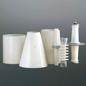
Svenska kraftnät (Svk) owns and operates the 220 kV and 400 kV transmission networks in Sweden. Due to safety concerns, composite type hollow core insulators were introduced at Swedish substations by the late 1990s, relatively early compared to other TSOs, and it has since become Svk’s technical policy to use only such insulators for all apparatus. Until recently, however, there were no detailed specifications for post insulators on this network, which could be supplied either in porcelain or of composite type.
This edited contribution to INMR by engineers at SvK in co-operation with, Igor Gutman and staff at Independent Insulation Group reviewed results of research that revealed no major problems with hollow core insulators. This work also confirmed that porcelain post insulators are a good alternative in clean environments and that more detailed specification is needed for composite post insulators to ensure their reliable long-term performance.

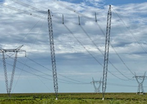
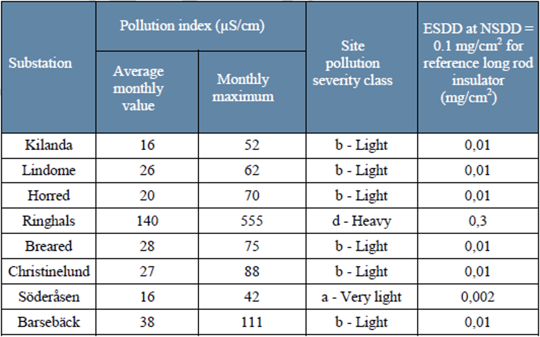
Pollution levels in Sweden are relatively low and most of the country is considered either level a, “very light” or b, “light” as per IEC 60815-1. Only one or two regions exhibit higher pollution levels (see Table 1).
Most of Svk’s composite hollow core insulators are used in applications on circuit breakers and instrument transformers and service experience has been and remains good. On the other hand, composite type post insulators have shown indications of weakness substations. Since there were no detailed specifications at Svk for substation post insulators, it was possible to supply these both in porcelain and in composite type. The first post insulators of composite type were only installed in recent years and this was mostly due to price and delivery lead time advantages offered for contractors building substations. No specific requirements were requested by Svk.
Based on concern that this lack of detailed requirements for composite insulators might lead to problems over the long run, in 2014 Svk decided to change its substation specifications. The new specification, made possible by relatively low pollution levels, was that only porcelain post insulators could be used. The conclusion was that pollution at the vast majority of substations was low enough that porcelain insulators could be applied with little to no future maintenance requirements. At the few substations exposed to higher pollution levels, RTV-coated porcelain posts were to be used.

Research to Assess Condition of Insulators
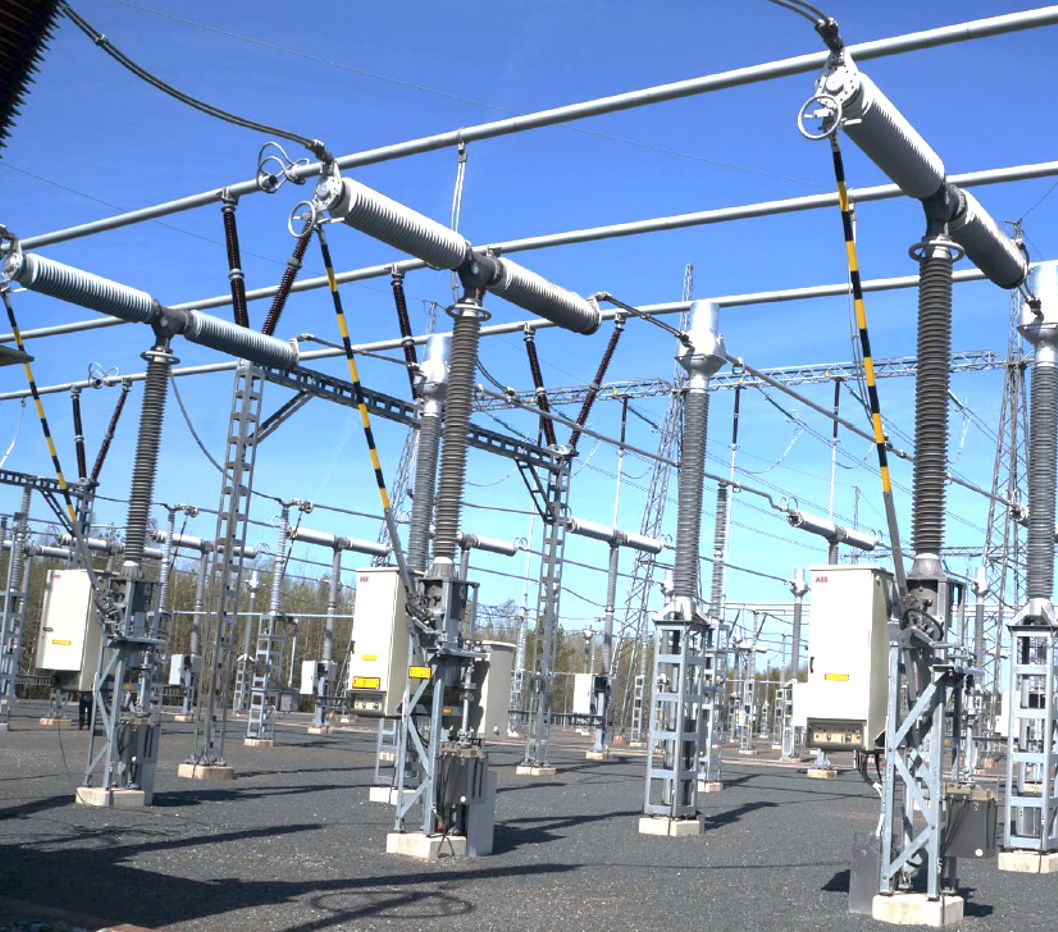
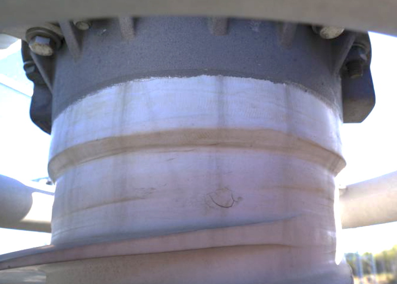
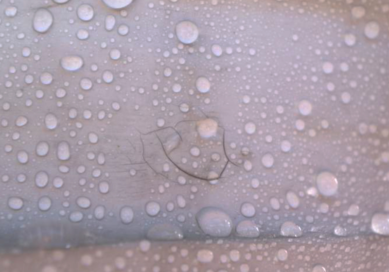
Inspections were performed by experts from STRI and I2G on composite insulated 420 kV circuit breakers that had been in service for about 20 years (see Fig. 1). Average measured hydrophobicity was good at HC 1 to 2 (based on the IEC scale HC 1 to7 where HC 7 is fully hydrophilic). Only four of the 27 insulators inspected had some minor surface cracks, most likely due to repairs during the manufacturing process. Absence of any traces of discharge activity as well as the high hydrophobicity levels around these cracks allowed them to be considered as only minor deterioration (see Figs. 2 and 3).
Some biological growth was also observed on the surface of insulators but this caused only minor local reduction in hydrophobicity and was therefore not deemed a cause for concern.
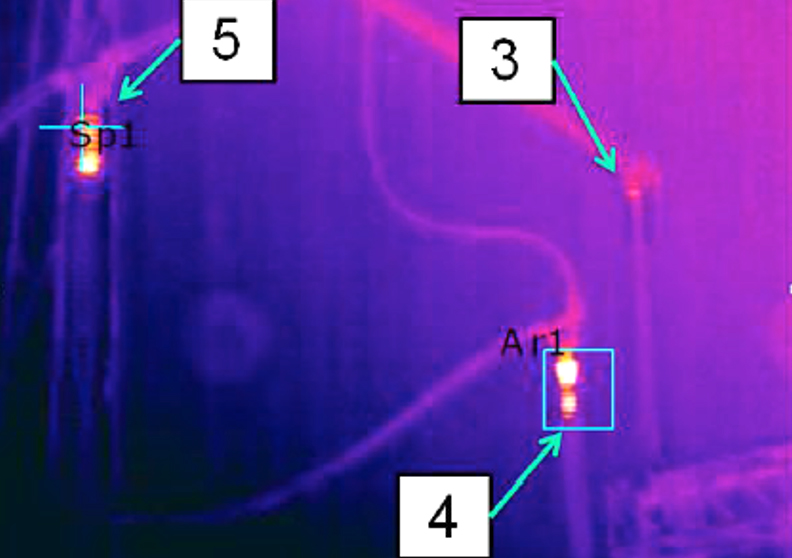
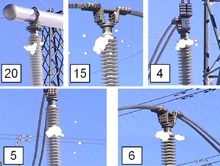
In May 2015, during routine inspection of connectors at a 420 kV substation, hotspots were discovered along several insulators. Subsequent investigation focusing on insulator condition showed that about 25% of these insulators had visible damage. For example, one insulator at a substation that was only three years in operation had damage rated as Class 4 (where 5 is considered highest according to CIGRE TB 481). Moreover, several punctures were detected in the housing of another (see Fig. 6). These findings led to research to establish the root cause of this damage, which involved inspecting the full inventory of insulators in service.

Also, Svk began a comprehensive program to investigate its population of installed insulators with the goal of evaluating their long-term performance. This program consisted of the following:
• electric field calculations (involving 11 combinations of different insulators with/without corona rings);
• inspection of insulators in service by IR and UV diagnostic techniques under energized conditions followed by close-up visual inspection of insulators under de-energized conditions (9 substations were inspected);
• laboratory investigation of insulators removed from service (18 insulators from 5 substations that had been supplied by three manufacturers).
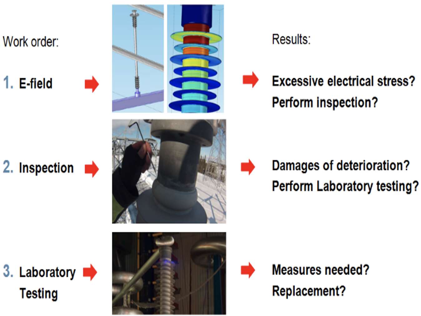
Several composite station post insulators were inspected close-up during scheduled outages to assess possible risk of damage accelerated by high electric stress (e.g. many insulators were installed with no grading rings). These inspections revealed a number of issues beyond improper electric field grading, including hotspots, punctures, defects related to poor quality control and deficiencies related to poor composite post insulator design and production. Several of the insulators inspected were sent to a specialized laboratory for additional testing. Fig. 7 illustrates the methodology used in this investigation.

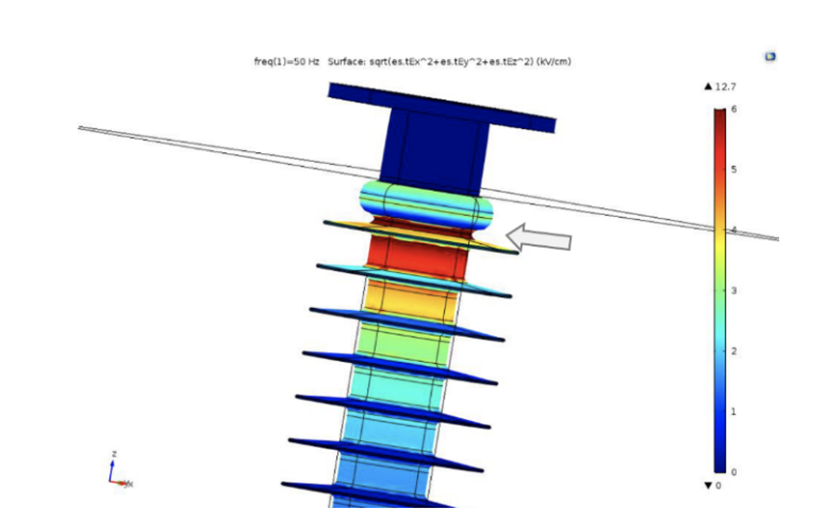
Electric Field Calculations
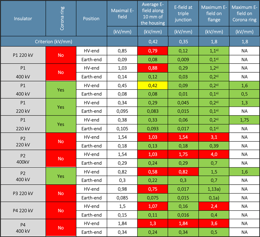
Electric stress on several composite station post insulators was calculated using FEM modelling in the Comsol software program. Results showed that the high voltage end of the composite station post insulators installed was heavily overstressed, i.e. electric field on the surface was well above the internationally accepted criterion 0.42 kV/mm. Fig. 8 presents an example of calculated electric field. Subsequently, electric field was calculated on all types of installed insulators (220-400 kV) and for the different service configurations (i.e. with/without corona rings). Table 2 provides results of these simulations. For most, electric field was too high in comparison with the recognized criterion.
Laboratory Investigation
The main objective of laboratory testing was to evaluate the severity of the deterioration of the punctured insulators. It was also seen as important to estimate the predicted performance of these insulators. The following tests were performed:
• high voltage test with IR and UV inspection;
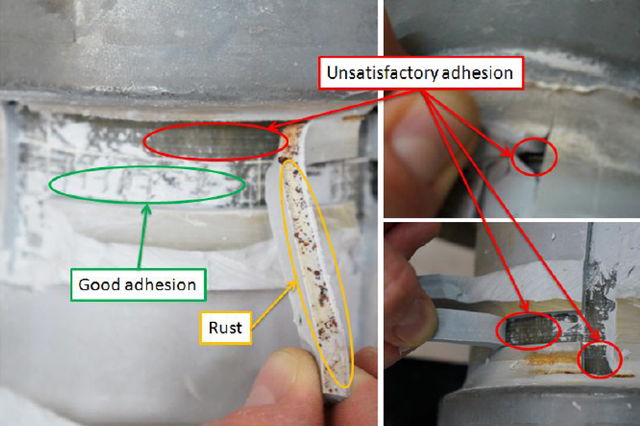
• adhesion test;
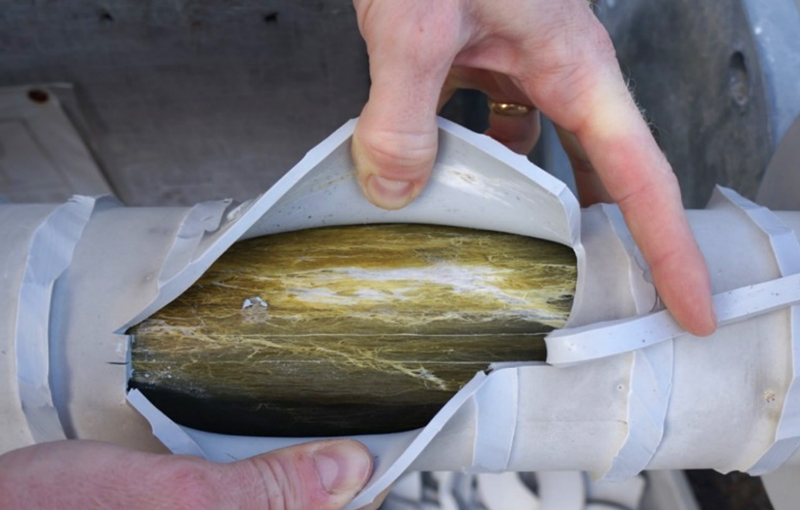
• dissection;
• dye penetration.
Experience with the standard IEC steep-front test revealed that it was not able to identify insulators with low levels of core to housing adhesion, which had been confirmed as the primary root cause of hotspots, discharges and punctures.
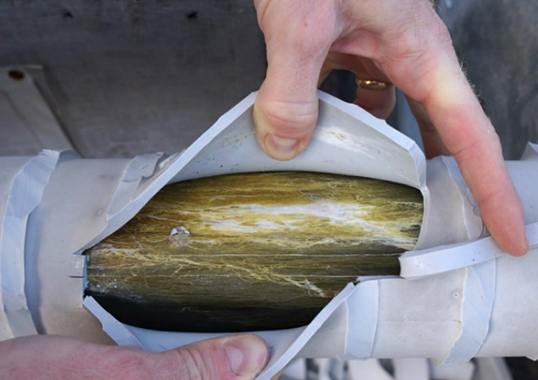
Dissection followed by visual inspection and the dye penetration test confirmed that damage under the silicone rubber was extensive at some substations. Sometimes such damage consisted of a tracking mark on the surface of the core. Sometimes the rod itself (epoxy resin) was eroded and had become semi-conductive. This meant that the insulator would inevitably fail either mechanically or electrically in the long-term. If the insulator was punctured, this meant that a semi-conductive path had already developed in the interface and was propagating due to high electric stress (especially if there were no grading/corona rings installed).
Action Plan
Several Svk substations were equipped with composite station post insulators and more than 1000 such units from different manufacturers were identified. For example, experience collected from investigation of insulators manufactured by suppliers P1 and P2 was similar and not positive. Results of testing showed that all these insulators had areas with low levels of adhesion. Not surprisingly, insulators from these manufacturers were found to have experienced severe damage during service, most likely correlated with their low level of core-housing adhesion. Therefore, to ensure reliable operation, it was deemed necessary to replace all these insulators. Morever, until replacement was complete it was recommended that IR and UV-inspections be performed annually to monitor degradation and be certain it had not yet become critical.
It was also concluded necessary to replace insulators from supplier P3 since these were overstressed electrically. As a point of interest, the cost of such further investigation and mitigation for only 18 installed insulators was most probably higher than the replacement cost.
Insulators manufactured by supplier P4 were found to be overstressed electrically and thus exposed to corona activity. Several already had cracked seals at the high voltage end while some were entirely devoid of seals, which indicated lack of suitable quality control. These issues would almost certainly shorten their service life.
Given that more than 500 of these insulators were already in operation and that there were not yet any clearly identified failure risks, the following scenarios (or combination thereof) were considered:
• insulators should remain in operation since most are equipped with proper grading/corona rings. But these insulators should be regularly assessed by IR/UV and those with critical degradation should be replaced;
• correctly-dimensioned corona rings should be installed on all insulators where required. Only infrequent assessment by IR/UV is needed and only those insulators that have reached a critical degradation level should be replaced;
• Total replacement.
After final analysis, it was decided to replace most of the identified insulators within the coming 10 years and this project of maintenance and replacement of composite type post insulators at Svk substations is ongoing.

Conclusions
Due to lack of proper quality control, post insulators installed at 420 kV and 220 kV substations in the Svk network are not all of satisfactory quality and some must be replaced or extensively maintained. Such replacement requires outages, which typically cost much more than ensuring adequate quality control during design, construction and equipping of substations in the first place. It is therefore recommended to invest in quality control rather than to invest in remedial actions after the fact.
Quality control is essential to reliable long-time performance of composite type post insulators. While the standards provide a good basis for the manufacturing these insulators, following existing standards alone is not sufficient to ensure long service life. More comprehensive testing is needed to obtain a product with good long-term service performance.
Two main factors that influence service life expectancy of these types of insulators have been identified:
1. Design should provide low levels of electric field on the surface of the housing in critical areas, according to internationally accepted criteria for maximum electric field. Electric field calculations are recommended to verify these requirements are being met;
2. Adhesion between the core and the silicone rubber housing must be high. Quality of adhesion is influenced both by material and by manufacturing process. Reliable test methods are now being included in IEC standards.
Proper technical specifications are needed to select reliable composite type post insulators. In the case of Svk, given the past lack of such specifications and considering low local pollution levels across their network, porcelain post insulators are now deemed sufficient for most applications.

References
• J. Philips, A.J. Maxwell, C.S. Engelbrecht, I. Gutman, “Electric Field Limits for the Design of Grading Rings for Composite Line Insulators”, IEEE Transactions on Power Delivery, Vol. 30, No. 3, June 2015, p.p. 1110-1118
• Gutman, P. Sidenvall: “Optimal Dimensioning of Grading Rings for Composite Insulators”, INMR, Issue 109, 2015, Q.3, p.p. 79-89
• Gutman, A. Dernfalk, J. Lundengård, P. Sidenvall, A. Deckwerth, L. Diaz, K. Halsan, M. Leonhardsberger, M. Radosavljevic, P. Trenz, K. Varli, K. Välimaa: “Test methods and criteria for validation of functional properties of composite insulators related to materials and interfaces”, CIGRE-2022, D1-10828].