Fibre optic technology, which is immune to EMI and RFI, is one of the solutions to the challenges of digitalizing substations for capture and transmission of data. It also achieved a high level of maturity that has helped push down cost. Moreover, optical sensor technology does not need a power source at the measuring point and the light source can be hundreds of meters away – even outside the station.
But installing fibre optic cable at a substation is itself challenging given that it must pass through insulators. This edited contribution to INMR by Markku Ruokanen at PPC Austria Holding explains a method to manufacture a fibre optic hole in ceramic insulators. It also explores potential future applications in monitoring forces, movement and vibration of ceramic insulators as part of a digital substation.
Introduction
Rayleigh, Brillouin and Raman scatterings in fibres result from interaction of photons with localized material characteristics such as density, temperature and strain. For example, an acoustic/mechanical wave generates a dynamic density variation that can be affected by local temperature, strain, vibration and birefringence. By detecting changes in amplitude, frequency and phase of light scattered along a fibre, a distributed fibre sensor can be realized for measuring localized temperature, strain, vibration and birefringence over lengths ranging from meters to one hundred kilometres. Such measurement can be made in the time domain or in the frequency domain to resolve location information.
With coherent detection of scattered light, changes in birefringence and beat length for fibres and devices can be observed. These distributed sensors can then be used to prevent disasters through structural monitoring of pipelines, bridges, dams and railroads. A sensor with centimetre spatial resolution and high precision measurement of temperature, strain, vibration and birefringence can also find application in aerospace, smart structures, material processing and the characterization of optical materials and devices.
The conventional sensor piezoelectric sensor is constrained under high temperatures. Its crystalline nature dictates a well-determined Curie temperature as a limit and proves inadequate when measuring static quantities due to charge leakage. These limitations mean that piezoelectric sensors are an unsatisfactory solution whenever there are requirements for reliability, hardiness and ease of incorporation, e.g. situations such as embedding sensors in aerospace wing components, in large induction motors or on high voltage power lines.
With development of opto-electronic technologies and increasing related industrial requirements, optical fibre sensors have now become widely accepted and achieved technical maturity. Their advantages are significant, especially for applications in harsh environments such as oil field service, civil engineering, navigation, high voltage, etc. Opto-electronic sensors are immune to electromagnetic interference and radio frequency interference (EMI/RFI) and are also small and easily integrated into networks. Other advantages include extremely high sensitivity at low frequencies, low harmonic distortion (THD), high signal-to-noise ratio (SNR), high signal quality, long term reliability and stability and very low losses on long optical data connections.

These days, standard industrial sensors such as optical microphones, optical temperature sensors, optical accelerometers and vibrometers are all available from multiple manufacturers. Among the practical applications for optical sensors, the most common are fibre optical geophones for ocean seismicity measurement, Raman optical time domain reflectometer (ROTDR) for down well distributed temperature sensing and optical vibration sensing systems for protecting petroleum pipelines. Indeed, the need for fibre sensors has increased rapidly. In this fast-developing market, manufacturing volumes have increased exponentially, leading to significant reduction in costs.
The fibre optic current sensor (FOCS) is already in use in high voltage applications and fibre optic post insulators have been delivered now for over 20 years. The FOCS utilizes the Faraday effect that causes polarization of linearly polarized light to rotate in the presence of a magnetic field, when propagating in a material that exhibits this effect.
CLICK TO ENLARGE
The FOCS and related technologies have been widely studied and there are numerous articles.
Creating Fibre Optic Hole in Ceramic Insulators
The technical challenge in using fibre-optic technology with ceramic insulators relates to how to manufacture them with a 15 mm wide straight 3 m long hole. The C-130 porcelain mass is extremely hard and requires special drilling heads. Moreover, keeping the hole straight across the entire length of the insulator is another technical challenge. Together, these make drilling time consuming as well as costly with conventional technologies.

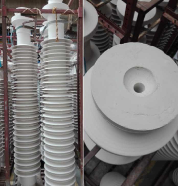
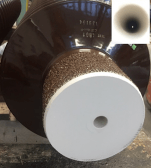
Manufacturing such a precise small hole using the plastic extrusion process for producing ceramic insulators would not be possible and industrial engineers have had to find a smarter way than drilling or extrusion. Fortunately, PPC has been able to take advantage of years of experience with the cold isostatic pressing (CIP) process and the possibilities this technology offers. Firstly, a fine, carefully controlled granulate with highly specific grain-size distribution is prepared. A cylinder is filled with granulate, which is pressed to over 1000 bar pressure, resulting in a solid blank for shaping and firing. An insert is added to the cylinder at this stage. This insert remains in place during the compression phase and is removed after compression, before turning. Fig. 2 shows the ready turned blank with a fibre optic hole, ready for glazing and firing.
CLICK TO ENLARGE
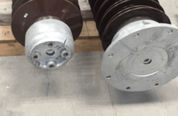
Once the insulator has been fired, production continues using the conventional insulator manufacturing process, including cutting, grinding, assembly and testing. Fig. 3 shows a fired C30-850 post insulator with a perfectly straight 20 mm hole on its central axis. Fittings must be pre-drilled and the hole and threads must be protected during cementing. Fig. 4 shows assembled insulators.
CLICK TO ENLARGE
CLICK TO ENLARGE
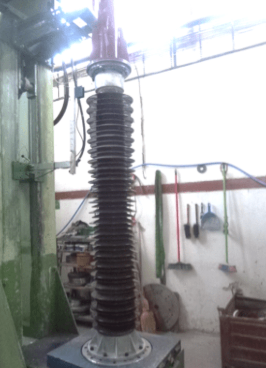
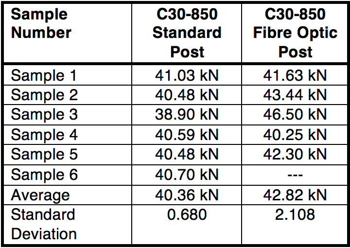
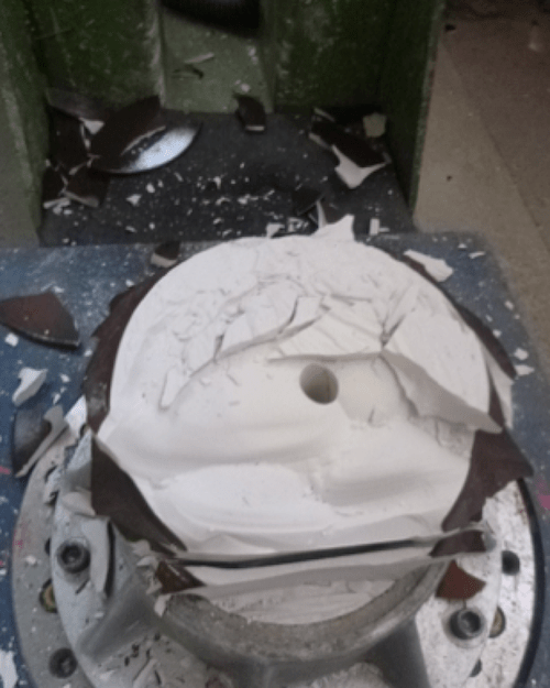
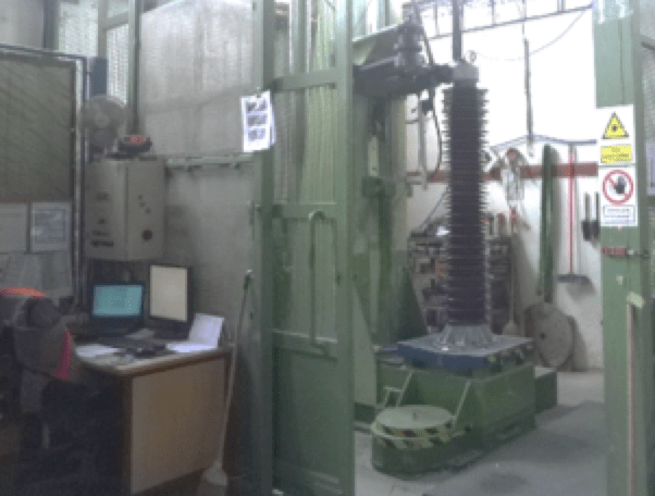
Being on the neutral axis, the fibre optic hole does not affect an insulator’s mechanical strength. To confirm this, samples of C30-850 post insulators with fibre optic holes were manufactured for benchmarking bending tests performed at PPC’s CAB plant in Slovakia. Fig 5 shows the set-up of these tests.
CLICK TO ENLARGE
CLICK TO ENLARGE
Tests results indicate that the mechanical strength of a fibre optic post insulator is unaffected by the hole in the neutral axis. Moreover, this destructive test also allowed observing whether breaking mechanism was identical to that of standard posts. All samples broke on the 2nd or 3rd shed from the bottom, where cantilever forces are greatest. Also, the breakage surface was identical to that of a standard post insulator. As a result, it can be concluded that presence of the hole does not affect strength, breakage mechanism or crack propagation of the ceramic body.
CLICK TO ENLARGE
Sensing Inside Porcelain
A post insulator manufactured with fibre optic hole allows a fibre optic sensor to be placed inside rather than simply drawing the fibre inside.
Stresses and strains in any solid material can be resolved into 6 components: three compressive or dilatative and three shears. These stresses cause acoustic waves in materials that vary considerably with their microstructure and elasticity. Frequency and amplitude of acoustic waves vary as well depending on source of the stress. These waves can be recorded using microphones and the data analysed. This technology is well known and already widely used in preventive maintenance and monitoring of rotating machines such as turbines, etc. The same principles could then also be used to monitor a ceramic insulator in a substation. Stresses are caused by wind, vibrations from the overhead line, external impact or movement of the switch when the insulator is used to transfer force as a torsion rod. Data collected during these events could provide the information necessary to better understand the physical shape and function of an insulator, or of the system in which it is a critical component. This information could then be added to a substation’s monitoring system.

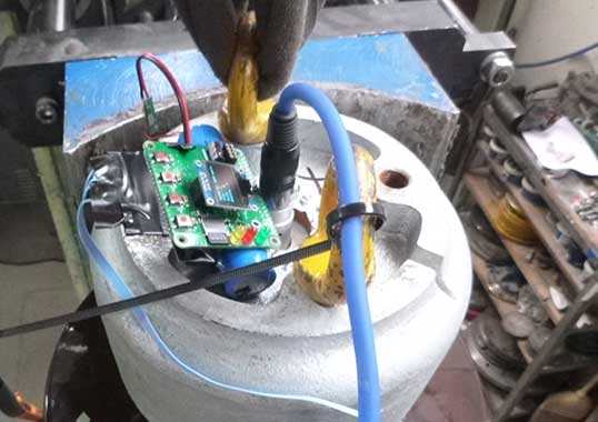
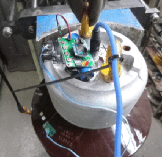
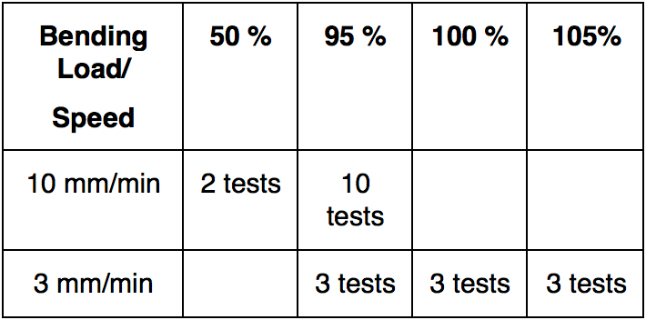
For example, a feasibility test was organized jointly between the Faculty of Electrical Engineering and Information Technology at the Slovak University of Technology in Bratislava and PPC Insulators CAB. An insulator was placed vertically into a bending machine at CAB’s test facility. A microphone was placed into a cable hole and the lower end of the hole filled with foam. The upper end of the hole was also filled with foam to isolate the microphone from the external environment. An accelerometer was then glued to the surface of the insulator using epoxy. Figs. 7 and 8 show the test set-up. The test insulator was loaded 21 times with different force and bending rates, as shown in Table 2.
CLICK TO ENLARGE
CLICK TO ENLARGE
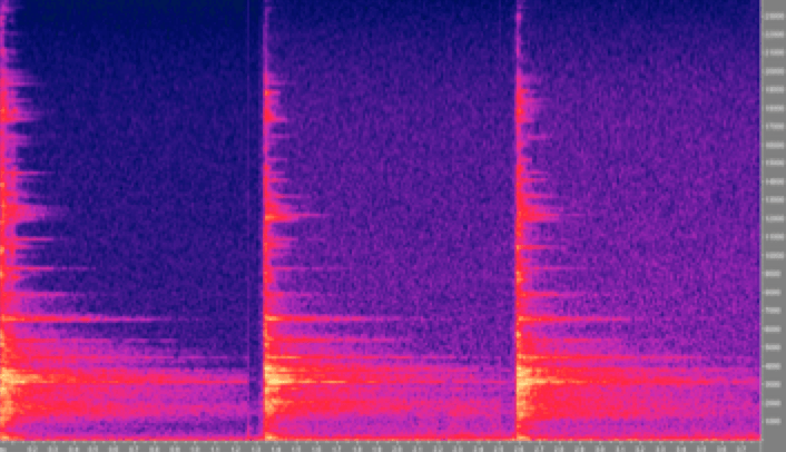
The first goal was to evaluate whether acoustic waves are dependent on internal stress of the insulator material. During the first test, the insulator was mechanically excited by tapping it with a metal rod in a direction perpendicular to the insulator’s axis. The measurement began with no force on the insulator. Responses to 5 taps, approximately one second apart, were recorded. Next, the insulator was loaded to 50% and again 5 tap responses recorded. This scenario was repeated for a 95% load. Responses to taps were individually normalized to have the same amplitude. Fig. 9, for example, shows three normalized impulse responses at loads of 5%, 50% and 95%. It was therefore concluded that stress level of the ceramic does not affect acoustics signals.
CLICK TO ENLARGE
CLICK TO ENLARGE
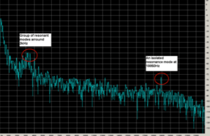
Fig. 10 shows measurement sets for two groups of resonant modes. The first is approximately 3 kHz and the second is a single resonant mode at 18.85 kHz.
CLICK TO ENLARGE
When compared, resonant modes at the load values indicate they did not have direct correlation to load and cannot be used directly to determine load acting on the insulator.
A neural network can find connections between events in processed signals that are normally hidden from view or are too complex to be processed by an individual. But proper training of the neural network is essential for correct operation and quality of the training process depends on sample size. For example, a sample size of 21 measurements is insufficient to train a neural network. Rather, sample size should be at least 100 times greater and even then would not guarantee success of this approach.
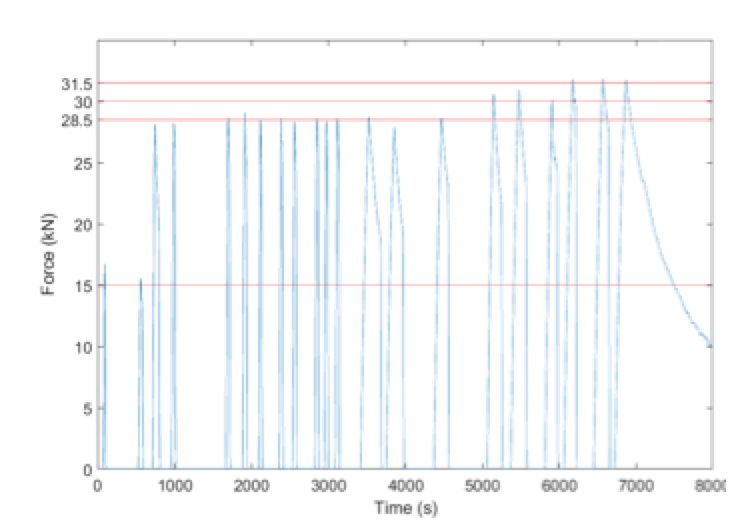
Accelerometers can be used to measure vibration, direction and magnitude of acceleration and vector direction of gravitational acceleration. Since in this case the insulator was fixed to the test machine, it was only possible to measure vibrations and gravity acceleration. Measured vibration data was similar to acoustic data and the most valuable data came from measuring angle of gravitational acceleration. After filtration and processing of data, it became possible to calculate deflection of the insulator and correlate this to bending load. Fig. 11 shows processed measurement data as bending force over time.

It was observed that bending was not 100% reversible since the insulator did not return to its original position. In this case, the testing loads were extreme and it is unlikely that any insulators operate permanently at 95% nominal strength. A different insulator will have a different ratio between bending force and deflection. As such, measuring bending ratio for each individual insulator would be required to confirm a systematic correlation. The feasibility test also suggested that any system using ceramic insulators with optical sensors would require a calibration process after installation at the substation.
CLICK TO ENLARGE
Conclusions
Manufacture of fibre optic post insulators is possible in an industrial and cost-effective way using the isostatic technology. The fibre optic hole is on the neutral axis and does not affect mechanical performance.
It thus becomes possible to measure acoustic waves and vibrations inside a ceramic post insulator. Stress level of the ceramic does not affect acoustic signal frequency or propagation in the material itself. Measurements with an accelerometer showed good correlation to real measured deflection, which theoretically also allows indirect measurement of the force.
It was not possible in this case to detect direct correlation between applied force and measured acoustics wave given that the number of measurements was insufficient for proper training of a neural network to accomplish deep analysis.
A fibre optic hole allows addition of sensing and data gathering capabilities to the normal function of ceramic insulators. Once filtered and analysed, collected data can then be used for substation monitoring. In this regard, it is a first step toward an intelligent insulator that can sense its environment and provide important system data for substation and asset management. Further work will be needed to confirm repeatability of measured data and also to determine a correlation between load and acoustic wave.
References
[1] Xiaoyi Bao, Liang Chen: “Recent Progress in Distributed Fiber Optic Sensors” – Physics Department, University of Ottawa, Ottawa, ON K1N6N5, Canada. – May 2012
[2] Lucas Borges da Silva: “Optical sensors for acoustic detection” – Master Theses, Department of Physics and Astronomy, Faculty of Sciences of the University of Porto – October 2014
[3] Sacha Liehr: “Optical Measurements of Currents in Power Converters” – Master Theses, Microsystem Technology Group, School of electrical Engineering, Royal Institute of Technology, March 2006
[4] Klaus Bohnert: “ABB FOCS, Fiber-Optic Current Sensor” – ABB Switzerland, Summer Workshop of Swiss Chapter of IEEE PES, June 2005
[5] Moises Levy, Henry E. Bass, Richard Stern: “Modern Acoustical Techniques for the Measurement of Mechanical Properties” – Volume 39 Experimental Methods in the Physical Sciences – 2001
[6] Ľ. Černaj*, P. Kubinec, T. Závodník, M. Donoval, M. Ďurák (1): “Indirect Measurements of Bending Force on High Voltage Insulators” – Faculty of Electrical Engineering and Information Technology, Slovak University of Technology in Bratislava, (1) PPC Insulators CAB – May 2019