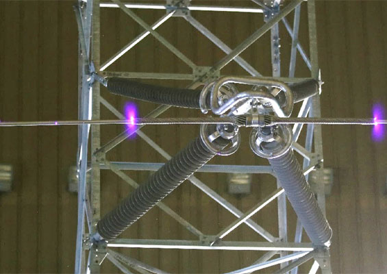
Application of composite insulators has become widespread across all HV, EHV and UHV applications due to detailed knowledge on both design and testing. However, use of such insulators for tower cross-arms is more challenging since there is the need to better understand their behavior as a mechanical tower component in combination with their basic insulation function. Indeed, working groups in IEC and CIGRE have been conducting a worldwide study to establish suitable design and test procedures for this new application.
This edited contribution to INMR by Adriano Dellallibera and other experts at both Hubbell Balestro and Eletrobras CEPEL in Brazil reviews local development and testing of a molded composite insulator cross-arm assembly (MICA) applied to the 230 kV system voltage.


Insulated cross-arm assemblies with composite insulators have been used on HV transmission systems for decades. This applies to line post insulators as per IEC 61952 and braced post solutions based on line posts supported by tension insulators as per Guides such as IEEE 1572.
But application of line post and braced post solutions has limitations related to the low longitudinal force withstand capabilities even though such applications now dominate in urban areas where establishing new right of ways has become a challenge. Due to mechanical limitations, it is most typical to find such applications only at voltage levels up to 230 kV.
Use of three or more composite insulators to design an insulating cross-arm able to the withstand longitudinal forces, as present on typical lattice towers, is a recent development. Yet it is fast becoming a disruptor to existing tower and line design, with clear impact on line compaction as well as on uprating of existing transmission towers. The resulting insulated cross-arm can withstand tri-axial forces on lines above 230 kV and even up to UHV applications.
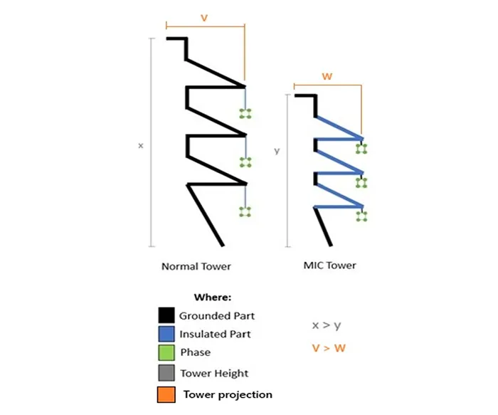
Application of insulating cross-arms is now being studied within the power community to generate deeper knowledge on design concept, relevant electro-mechanical considerations and adequate test procedures that cover all requirements from this technology and its impact on transmission line design.

Construction
Based on design of a typical 230 kV single circuit line (as established by Eletrobras), a double V MICA was designed to withstand both electrical and mechanical requirements assigned for line structures. The tower manufacturer (in this case SAE Towers) designed a 230 kV single circuit lattice tower in triangular configuration to be equipped with MICAs able to withstand worst case conditions for mechanical performance, as per applicable standards.
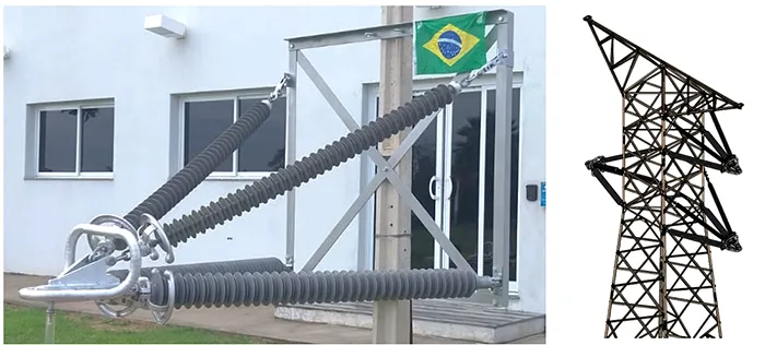
Mechanical Testing
Eletrobras CEPEL conducted characterization testing on the line post insulator rods to verify elastic properties and compression at an eccentric loaded rod. This is a key feature related to assessment of Euler buckling load for a MICA design and relates to combined loads and increase on the longitudinal force withstand compared to a braced post solution.
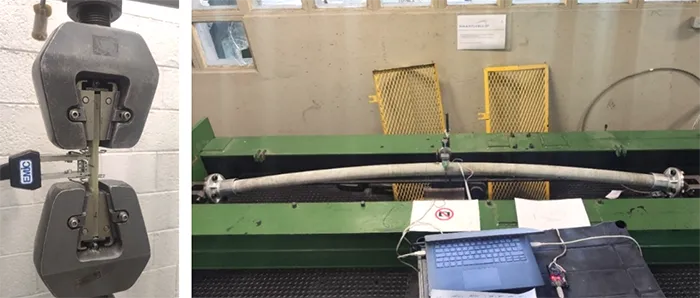
The most relevant element on MICA design related to growth on the longitudinal mechanical behavior is the line post insulator in the base triangle working at compression forces. Due to the orthotropic nature of FRP rods, the mechanical and elastic response of such an insulator is related to force direction. According to Euler’s critical buckling load expression, the buckling capacity relates to axis symmetry of this force and the kind of freedom in the movement at the end points of the compressed rod by:
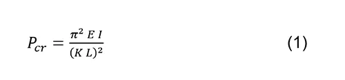
where:
PCR = critical axial force for flexural buckling of rod, N,
E = elasticity modulus, MPa,
I = Inertia moment of rod cross-section area, I=(π d^4)/64, d is rod diameter, mm,
K = effective length factor, that is related to rod end degree of freedom (can vary between 0.5 and 2.0, from none to full freedom – for this case their value is 1.0),
L = effective length (unsupported) of rod (mm).
This expression only applies to high slenderness ratios, as is the case of long rod line-post insulators.
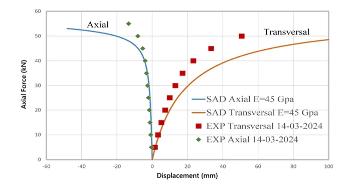
The testing conducted presented a good agreement of theoretical to practical behavior, as shown by Fig. 4. Results according to a geometrically non-linear spatial beam finite element analysis are compared to the experimental data for the long rod. Good correlation was found for small displacements, scattering gradually for greater displacements, leading to conservative elastic properties for Euler buckling load calculation in MICA design. This leads to a safe approach.
The full tower for this project was mechanically tested at the SAE Towers Test Station for worst-case scenarios for the mechanical 3 axis forces expected in the field. From the MICA point of view, the most relevant mechanical loads were applied for cases shown in Table 1.
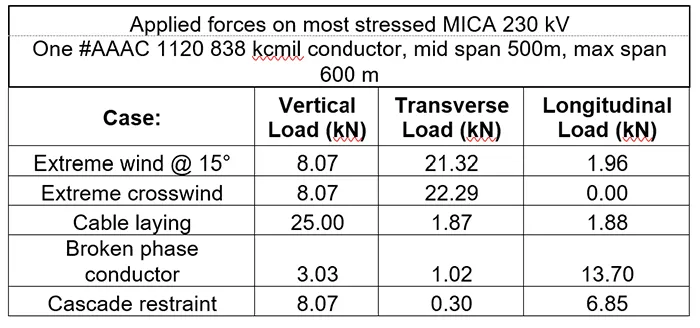
For this project, in those cases the applied forces had shown to be below the expected maximum combined loading for the MICA itself. A large trial test on a reaction wall has been planned to find the ultimate strength of this design.
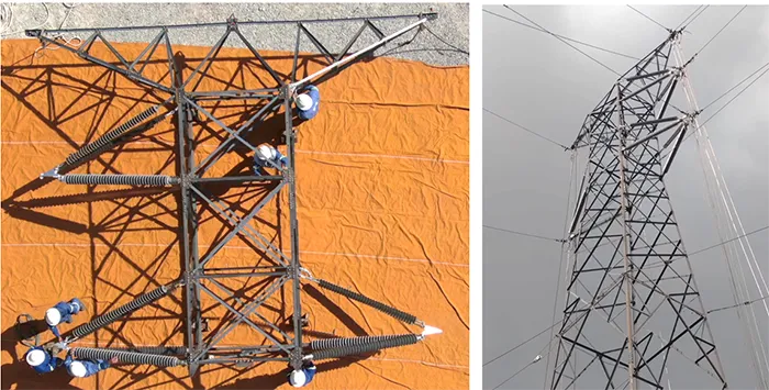
Full tower tests, although mandatory, showed a result influenced by tower movement, with no visible buckling in the MICA line posts insulators under compression conditions. Future work by CIGRE and IEC WGs and a recent IEEE publication should address more specific mechanical testing for the insulating cross-arm. Both designers and users will be involved in this improvement.

Electrical Testing
All electrical testing was performed at CEPEL Labs in Rio de Janeiro. It is important to point out that this laboratory is almost at sea level, which means that in some testing the correction factors at applied voltages can move to lower than applied voltages. Of course, all results shown are corrected, with correction factor k in some cases higher than 1.0.
This design of MICA that is adequate to 230 kV system voltage level requires withstand voltages according to IEC standards, as shown below:
• dry and wet power frequency withstand voltage level: 460 kVRMS
• lightning impulse withstand voltage (BIL): 1050 kVPK both polarities
• RIV measurement @ 1Mhz [19] and 156 kVRMS: maximum 500 uV
• minimum positive corona extinction voltage: 156 kVRMS
• power arc withstand capability: 30 kARMS
In addition, as part of the research, other testing was also performed:
• critical lightning impulse flashover voltage determination (up-and-down method)
• critical wet switching impulse flashover voltage determination (same method)
• withstand impulse voltages by statistics approach (V10%)
High Voltage Power Frequency Testing
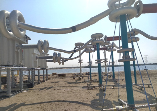
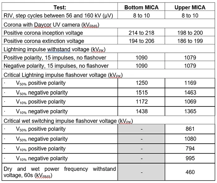
For electric tests in this case, a section of the real tower with two 230 kV MICA and the ground wire metallic cross-arm were mounted in the HV Lab, with tubes simulating all the wires of the real tower (including the ground wire). The bottom phase tube was erected to 6.0 m above the HV laboratory floor. As seen in Table 2, the upper phase has a small reduction in minimum arc distance due to the metallic ground wire cross-arm, and this plays a role on the testing numbers.
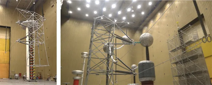
voltage tests.
This is an innovative way to test this tower, since differences in height to the ground from both MICA and the presence of all wiring reflect some differences in test results. The phase tube not being tested was kept grounded as well as the tower and ground wire.
Note: measured minimum arc distance on the setup structure results:
Upper MICA = 1.870 mm, bottom MICA = 2.060 mm
For RIV and corona effects, the design approach was conservative, considering the complex geometry on the ‘live’ nose of the MICA and the design rings shown an efficiency higher than needed, as per measured RIV values close to background noise.
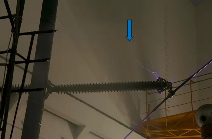
Corona inception and extinction voltages also surpass values established for the MICA voltage class (UM = 245 kV – Test voltage = 245/√3 * 1.1 = 156 kV). In fact, it is possible to see in Fig. 7 that the nose and insulator rings have no ionized point at higher than established test voltage, with corona inception starting at 214/198 kV (bottom/top cross-arm values) from the cable protecting armature.
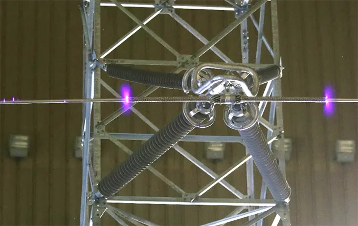
Fig. 7: Positive corona at inception voltage starts in borders of cable protection armature hardware.
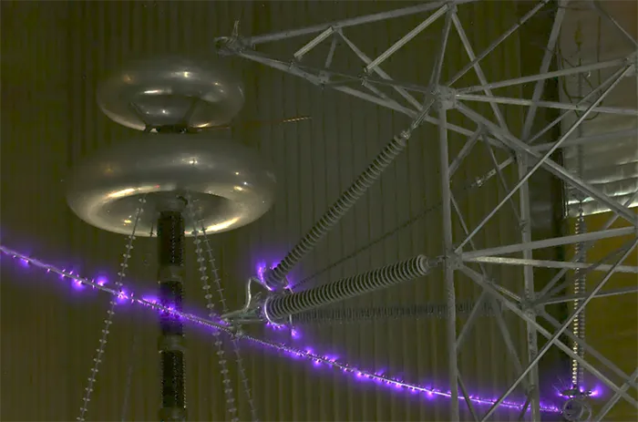
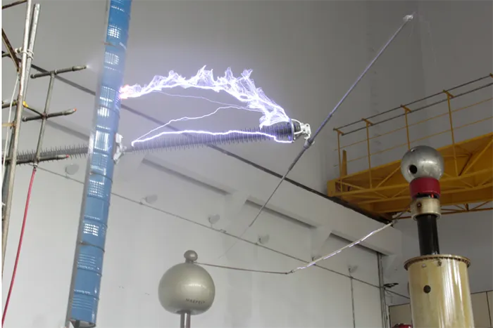
The wet power frequency withstand voltage was also performed using this same circuit arrangement (as in Fig. 6 right) and with no remarks (see Table 2). CEPEL does not perform power frequency disruptive testing for safety reasons.

High Voltage Impulse Testing
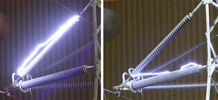
The effect on tower position impacts actual arc distances of the MICA assembly and the complex geometry produces expected deviations in voltage numbers (see Table 2). Influence on design of the MICA components can play a role in such behaviour and must be considered by both MICA and tower manufacturers. In this test program, for example, the balance found in different disruptive points showed that both MICA and tower manufacturers took care to avoid ‘hot spot’ weak points and the expected full withstand voltages.
Power Arc Testing
One 230 MICA was assembled on a portion of the tower in the HP Laboratory at CEPEL to be tested for power arcs. The arrangement on the test circuit was agreed by the research team to be equivalent to the real case tower and fulfill the power arc test standard as closely as possible. The test circuit constructed was like Design C in this standard, with a balanced supply of the SC current by the line cables and unbalanced return on the tower section. A vertical mechanical load was applied on the connecting point on the MICA nose.
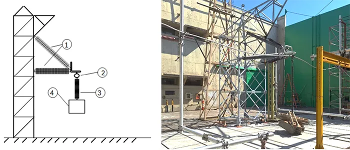
Testing was performed with effective current of 30 kA by 0.1s, as defined by the minimum requirement for a 230 kV insulator in Brazil’s power system, the arc current applied twice on tension and line-post insulators, with good result and no remarkable damage. Final mechanical verification was applied only to the tension insulators and with no remarks.
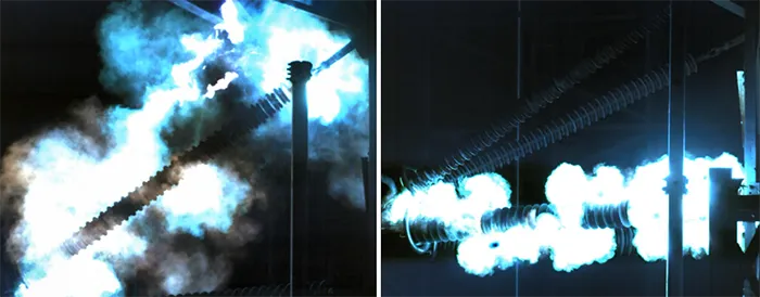
It is important to note that the insulators used in this project (long rod tension insulator as well as line post) had already been tested to power arc withstand up to 50 kARMS in individual applications.

Discussion & Conclusions
It has been verified that the complex geometry of a MICA design plays a role in the discharge paths on the impulse up-and-down and disruptive discharge in power frequency voltage testing. This has also been observed when testing line post installations that have different behavior than the usual insulating chain for standard tower construction.
For the MICA manufacturer, clear understanding of the effects of geometry on electrical behavior of insulating cross-arm assemblies is mandatory. In the case of line upgrading/uprating on existing towers, this is a highly sensitive parameter for the MICA designer. The face elements at the tower on the MICA position must be evaluated to consider their impact on disruption phenomena.
The confluence of the 4 insulators in the live point of the MICA at the nose demands careful design of insulator protection rings for their proximity. An EF simulation has been shown to be a useful tool to visualize and adjust their design to prevent damage to the insulation material due to concentrated electric fields at this point of confluence. In this work, CEPEL conducted EF simulation using COMSOL® software.
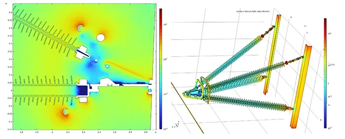

Simulation results showed well protected HV live parts with highest concentrated fields at outer ring parts. EF on the insulating surface was stable and well distributed, as required in state-of-the-art use of polymeric insulators and field concentration agreed with Fig. 8 in terms of corona effect.
In power arc testing, applied peak current showed that actual power arc capability on this MICA 230 kV design can be higher than tested. The IEC standard test method may need to be reconsidered for insulated cross-arm testing.
The appliance on some combined loading during the test can be considered by the WG’s on research and standard setting boards. This can require HP laboratories to have proper reacting walls to support the test set-up and mechanical loads involved. This can prove costly.
The current return circuit will always be the unbalanced one.
The arc current application can be distributed between both tension and line post insulators since they react in different ways to the power arc. Number of applications can reach up to 6 times, and the effect of this total number of power arc applications must be considered for all elements and needs to be studied, together with the combined loading that this research proposes.
The latest IEEE document on MICA application and testing proposes promising testing – especially both static and dynamic mechanical testing that will promote discussion and research worldwide. This document was still being written at the time this work was being undertaken.
It should be noted that mechanical behavior of MICAs during their time in service must be also evaluated. Impact of ageing on mechanical performance must consider that such devices are required to perform for at least 30 years, as per Brazilian utility expectations. Design must therefore meet this requirement. Additional mechanical testing of both new and pre-aged/stressed MICA will be useful and is still being developed.



References:
[1] – IEC TS 63594 ED1 – Work in progress by JWG 25 of TC 36 and TC 11 – Composite insulated cross-arms with voltage greater than 1000 V and DC voltage greater than 1500 V – Definitions, design criteria, test methods and acceptance criteria – Planned to be published in 2027
[2] – CIGRE WG B2.96 – Composite insulated cross-arms for new-build and retrofitted transmission line supports – WG started in 2025, planned to finish 2028
[3] – IEC 61952:2008 – Insulators for overhead lines – Composite line post insulators for A.C. systems with a nominal voltage greater than 1 000 V – Definitions, test methods and acceptance criteria
[4] – IEEE 1572-2004 – Guide for Application of Composite Line Post Insulators
[5] – R. Junior, C. K. C. Arruda, R. W. Garcia, J. C. Salari Filho, A. Dellallibera, The technological Disruption Caused by the Composite Insulator Crossarm in the High Voltage Transmission System, in IEEE 7th International Conference on Electrical Engineering and Green Energy – CEEGE, Los Angeles, USA, 2024 – Paper G3303
[6] – I. Kimoto, K. Kito, K. Ueno, Insulator Crossarms for 345 kV EHV Transmission Line, IEEE Transaction on Power Apparatus and Systems, vol. PAS-90, nr. 2, March/April 1971 – Paper 70 TP 628-PWR
[7] – IEEE Std. 2833-2024 – Guide for Overhead Transmission Lines with Composite Insulated Crossarm Supports
[8] – Eletrobras – Research project PD-00394-2113/2021– Reference term for a 230 kV MICA tower, 2023
[9] – IEC 60826:2017 – Design criteria of overhead transmission lines
[10] – IEC 60652:2021 – Overhead line structures – Loading tests
[11] – J.-P. Marais, Understanding Load Capacity of Post and Braced Post Insulators, EPRI PLS‐CADD Advanced Training and User Group, Power Line Systems, 2019
[12] – Estrella, L. F. – SAD/TLT program – Installation, register and data base – CEPEL report 7624, 2018
[13] – SAE Towers – Tower test report BL-R8240-CEP-114-23-001, April 2024
[14] – CEPEL test report DEE – 549/2025 – MICA 230 kV – High Voltage tests
[15] – CEPEL test report DEE – 1279/2025 – MICA 230 kV – Power arc tests
[16] – IEC 60060-1:2025 – High voltage test techniques – Part 1: General terminology and test requirements
[17] – IEC 60071-2:2023 – Insulation coordination – Part 2: Application guidelines
[18] – IEC 60071-1:2019 – Insulation coordination – Part 1: Definitions, principles and rules
[19] – NEMA 107:2016 – Methods of Measurement of Radio Influence Voltage
[20] – Q. Wang, X. Liang, Y. Shen, S. Liu, Z. Zuo, Y. Gao, Lightning flashover characteristics of a full-scale AC 500 kV transmission tower with composite cross arms, Engineering (2022), doi: https://doi.org/10.1016/j.eng.2021.09.021
[21] – CIGRÉ brochure 284 – Use of corona ring to control the electrical field along line composite insulators, December 2005
[22] – CIGRÉ brochure 794 – Field grading in electrical insulation systems, March 2020
[23] – IEC 61467:2008 – Insulators for overhead lines – Insulator strings and sets for lines with a nominal voltage greater than 1 000 V – AC power arc tests
[24] – ONS – “Operador Nacional do Sistema Elétrico” – Brazilian National Power Grid Operator, subchapter 2.7 – Minimun requeriments for transmission lines, Rio de Janeiro, release 2022.08, 2022