INMR presents selections from its archive of photos assembled over more than 30 years visiting power lines, substations, equipment factories and test laboratories across the globe.
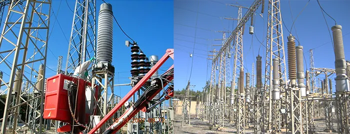
The average distance from the sea of substations on the Greek island of Crete is only about 4 km and several key stations are only meters from the coast. For example, the Linoperamata Substation, equipped with over 1200 insulators, has required significant maintenance due to frequent power interruptions that became a normal part of its operation. Then, as the station expanded with the addition of a 150 kV switchyard, special new measures were taken to diminish the severity of this problem. Toward 2000, a program began to coat all substation insulators with RTV silicone material. This effort produced almost immediate benefits and was continued every year thereafter. Crete remains among the networks in the world where most substation insulators are coated with RTV silicone.


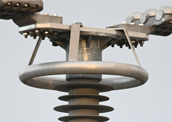
For its Browning Project in the 1990s, Salt River Project in Arizona was challenged with designing and constructing a 230 kV line in an urban setting where right-of-way was limited and aesthetics essential. A compact line design was seen as the best choice to reduce overall height of structures using single shaft steel poles and for matching a pre-existing 500 kV line – span for span and structure for structure. Because of the much longer spans compared to a previous similar 230 kV project, a pivoting horizontal Vee assembly was selected for most of the route. The stability of such an assembly is based on such factors as axis of rotation angle, span length, line angle, number of consecutive tangent structures and conductor slack. The assembly is allowed to rotate with line longitudinal loads and the vertical load is sustained by the suspension leg insulator. The axis of rotation angle constrains the assembly from rotating by forcing the insulator to lift the conductor. With a positive angle, the assembly is stable and this stability improves the larger the angle. However, if this angle is negative, the assembly can become unstable and can even rotate substantially. This is precisely what happened when a number of these assemblies rotated 90° during a windstorm with sustained winds of 40 mph. This caused the conductor to lay directly against the steel poles. Fortunately, this problem occurred prior to putting the line into service and there was no flashover nor line trip-out.
An engineering evaluation of this insulator assembly stability problem modeled the Browning line with its pivoting horizontal vee assemblies and concluded that the following factors contributed to this rotational instability:
• Too small an axis of rotation angle;
• Too many pivoting horizontal vee assemblies in sequence;
• Too great a number of small line angles;
• Long span lengths.
Potential solutions to this instability problem included:
• Adding longitudinal restraint (i.e. a braced horizontal Vee assembly);
• Periodic insertion of dead-ends or tension assemblies;
• Increasing the angle to axis of rotation;
• Decreasing the span lengths.
The solution eventually implemented was to periodically install braced horizontal Vee assemblies using a post insulator with a fixed base and a 3 in. diameter rod. This solution provided the required restraint to the assembly and line from wind-induced longitudinal loads.

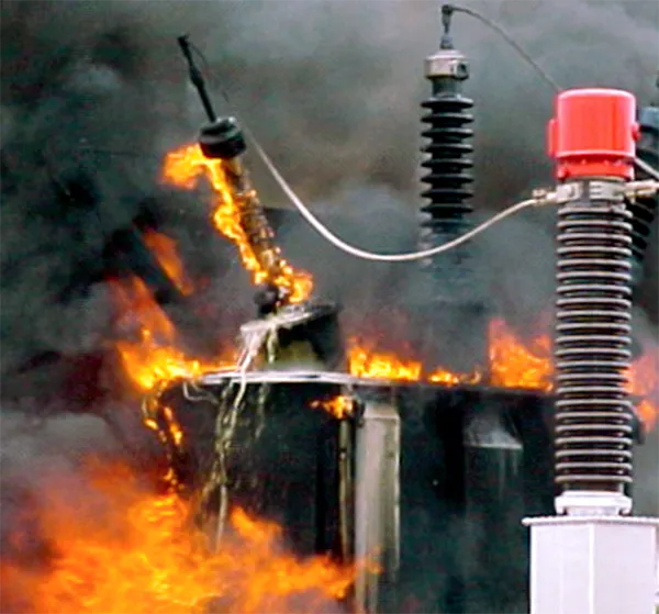
Bushings are among the most critical components of a power transformer and there is ample evidence that they are among the major initiators of failures. On average, risk of a large power transformer failure is assumed to be up to 1% per year of service. Furthermore, it is estimated that 10% of transformer failures result in serious fire, meaning that this risk is as high as 0.1% in each year of service. Almost 50% of all serious transformer fires are initiated by failure of OIP bushings and these are, therefore, properly classified as the single leading cause of transformer fires. A CIGRE Working Group (A2.37) determined that for utilities operating in Germany, Austria, Switzerland and the Netherlands bushings were typically responsible for circa 12% of major transformer failures. This proportion grew to approximately 17%, if the analysis was limited to transformers with service voltages above 100 kV. When performing a proper risk assessment, it is important not only to consider probability of failure but also impact of damage associated with failure. As an initial systematic approach, the goal is to reduce probability of failure itself. If failure probability cannot be reduced to an acceptable level for economic or technical reasons, impact of failure should then be reduced to a desired level.
Assuming transformer failure rates follow the well-known ‘bath tub curve’, failure rate at the beginning and end of a transformer’s life should increase. By performing a thorough factory acceptance test, probability of early failures tends to be significantly reduced since the material will be ‘pre-stressed’. It has also been shown that, towards the end of its expected lifetime, the probability of transformer failure increases rapidly. Probability of serious fire initiated by a transformer failure depends on bushing technology involved. In this regard, OIP bushings have a considerably higher likelihood of causing a serious transformer fire compared with RIP bushings. Also, choice of material of the outdoor insulator influences severity of any failure. Based on long-term field experience with well-known bushing technologies, the following is the approx. distribution of identifiable root causes requiring overhaul or replacement of a bushing:
• 80% leakage (only for bushings containing oil within the insulation)
• 13% deterioration of insulation
• 7% mechanical damage (mainly to porcelain insulators)
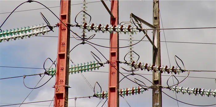
Vandalism, involving shooting and stone throwing, has been a major concern for a large electricity supplier near the coastal city of Recife in Brazil. Such problems have in some cases been so severe that power arcs have occurred along critically damaged glass strings, sometimes resulting in pin separation. One of the unusual measures used to combat this situation, especially in the case of tension strings on towers passing certain populated areas, has been the use of strings consisting of alternating glass and porcelain discs – something generally not recommended but which at least provided some security against this type of catastrophic outcome.

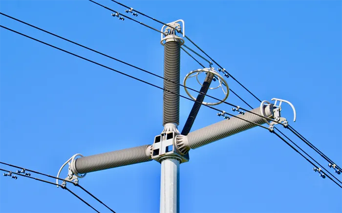
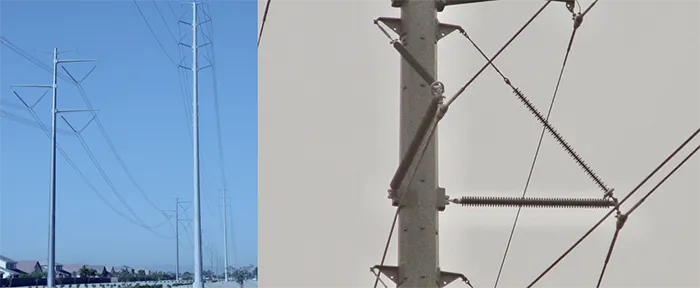
Designing a 420 kV line that meets the strict criteria needed to be acceptable to those living in urban and suburban communities presents a serious challenge. These criteria include relatively narrow corridor; low visual impact; high aesthetic appeal; and reduced electromagnetic field and audible noise – all the while also meeting basic performance requirements such as sufficient lighting protection.
Precisely this challenge was considered by TSOs in Nordic Europe, who were already facing an increasingly difficult task obtaining new right-of-ways. Specifically, these network operators wished to identify alternatives to laying expensive cable when upgrading transmission lines that pass through sensitive population centers. Fortunately, developments in hollow composite insulators by the early 2000s soon reached the stage where customized composite post insulators having high mechanical strength yet relatively low weight could be supplied. The compact design that became a reality incorporated a trio of hollow core insulators that utilized special foam to fill the space within their inner FRP tubes. Given the horizontal configuration of these insulators, it became necessary to increase the original optimized conductor phase spacing of 5 m to either 5.4 m or 6.4 m in order to account for the modified air gap between conductor and structure. Moreover, since earth wires had to be eliminated to achieve the desired compaction, a transmission line arrester with a polymeric housing was designed into the structure. Reviewing the advantages and drawbacks of this compact design, developers noted that it was not intended to replace conventional long-distance transmission but to be applied only in areas considered sensitive from an environmental perspective or where there were restrictions in available line corridor. It is also much less costly than cables for suburban areas where permission cannot be obtained to build conventional lattice structures. Another benefit was that electromagnetic field with this design is only some 40 per cent of what is normally encountered on conventional lines at this voltage. Similarly, right-of-way needed was only a third of the 18 m width generally required – a reduction of 12 m. Finally, simple installation with mounting of the entire pre-assembled superstructure onto the pole offered savings as well.

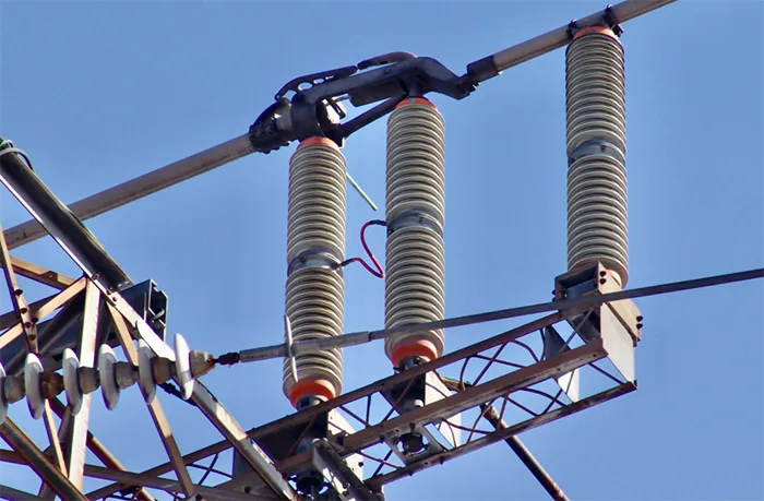
During the 1990s, researchers studied the specific types of flashover problems that affected insulators at the Hamilton Beach Substation, located in an area of heavy industry near Toronto. Among the more unusual of these were cases of wintertime flashovers affecting porcelain switch insulators, even though these had already been converted to units containing special resistive glaze, intended to offer superior pollution performance. The major problem here was that these RG support insulators were installed only about 50 cm apart. After collecting samples of the pollution which had accumulated on the supports, it was concluded that putting them so close together interfered with their normal voltage grading. As a result, in the event of a spark or any arcing activity, a flashover was quickly initiated, typically between the two insulators. The key to avoiding this problem was to suppress any initial arcing and this was accomplished by implementing a solution that saw a connective wire function as a bond between the center two flanges of the insulators. This served to restore the intended field and effectively suppress onset of arcing.
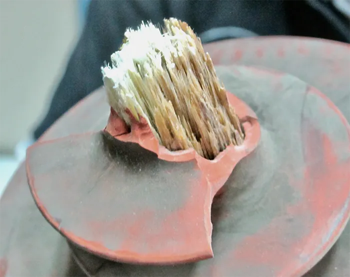
A failed composite insulator with fracture characteristics different from brittle fracture was analyzed by optical, chemical, thermal and standardized methods. This failure took place in November 2010 after 5 years’ service on a 500 kV AC line in Guizhou Province of China – an area of light pollution severity as defined in IEC 60815. Inspection of the line using of an IR camera had been conducted only two months before the incident and had identified a minor ‘hot’ spot along this unit located from 1.5 to 2 m from the live-end fitting. However, apart from the slightly elevated temperature observed, there were no other indications of imminent failure. Analysis revealed that the mechanical strength of the core material had been degraded by water induced ageing processes. Interfacial tracking at microscopic and macroscopic interfaces was identified as a further degradation mechanism. The origin of the failed insulator’s degradation process was assumed to have been the relatively weak adhesion detected between its sheath and core – making it especially prone to water accumulation by water vapor permeation and subsequent condensation. The observed sheath punctures and interface tracks consequently developed from sheath splitting caused by partial discharges and localized heating near wetted defects at the sheath-core interface. Once sheath puncture occurred, further water induced ageing of the thus exposed core could only accelerate. Results of this investigation emphasized the importance of good adhesion between the sheath and core of composite insulators when it comes to their long-term service performance.
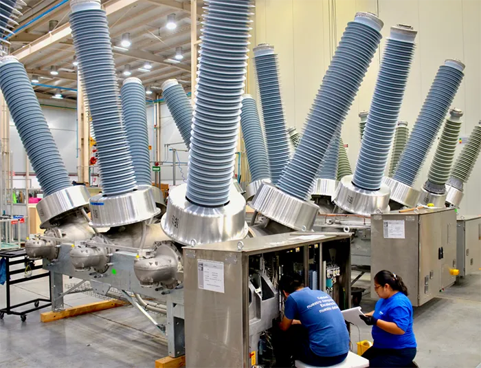
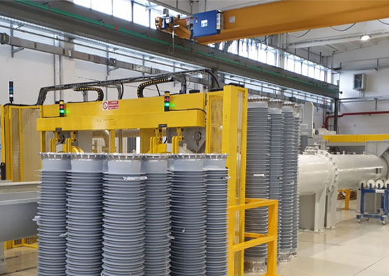
Built in 2011, the Siemens El Marqués circuit breaker plant in an industrial park in Queretaro, Mexico represented a significant expansion of a former factory. One of the buildings is devoted to assembly of complete breakers for the local as well as export markets. For the most part, this consists of cabinet assembly and wiring as well as combining the switches and drives from an adjoining facility with insulator housings that serve as bushings. As of several years ago, some 90 percent of the housings used each year were porcelain while silicone composite types were still regarded a specialty either for problem environments or for customers with special demands. Although end customers rarely specify a particular supplier for the bushings and are content to leave this choice to the breaker manufacturer, insulators are considered strategic, highly engineered components to meet the demanding electrical and mechanical requirements of a breaker. For example, one of the problems in the past has related not to any issues with the porcelain body but rather to how well it was attached to the flange. Before sulphur cement was replaced by Portland cement to improve bonding strength, there were occasional issues reported in the interface between the porcelain and the flange such that there was slight movement after several years’ service. Eventually, this could lead to leakage past the O-ring.
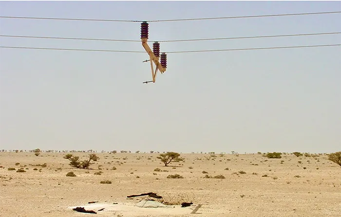
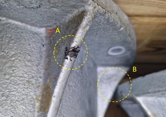
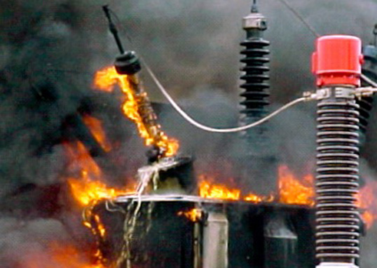
Pole failures are generally triggered by excessive leakage currents on polluted insulators that have become wetted. The main pollution source in the case of deserts is windblown calcium and quartz particles found in sand. Dampness comes from an increase in overnight humidity – especially during summer months – leading to formation of dew. Around dawn, as surface moisture starts to evaporate, insulators are left with dry as well as wet patches along their surfaces. Given the service voltage, the wet patches can be at different potential so that surface currents start to flow between them, commonly visible at night as blue flashes and referred to as dry band arcing. Since pollution levels are not uniform on each insulator, the cross-arm itself soon sees a rise in voltage as the current tries to reach earth by going down either the pole or the stay wire. Given the dry atmosphere, the pole’s cross-arm bolts tend to loosen due to pole shrinkage and thereby allow the arcing to occur between bolt and cross-arm strut. This can then ignite the pole’s ‘heartwood’ and a pole-top fire ensues. Sometimes these fires die out, in which case the cross-arm bolt is often left exposed at the center of a hollow burnt-out space. However, as the day heats up (often to over 50°C during summer), the pole can smolder all the way to its base and leave the cross-arm hanging from the conductor, suspended in air.

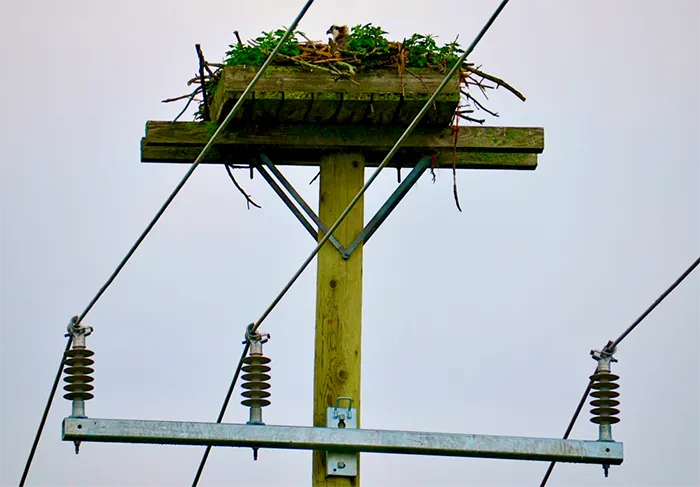
Service experience suggests that from 70 to 80% of outages on overhead lines can be directly attributed to birds. Even though these types of outages are almost always characterized by successful automatic re-closure, power utilities are still concerned. In older days, the concern was due mainly to old type oil circuit breakers that required maintenance after each cycle of about 15 operations. At present, the worry is due more to requirements for power quality and availability, since many utilities now set their own internal rules on average outages permitted each year per 100 km of line.
It is important at the early stage of any discussion on problems of birds and power lines to distinguish the situation for distribution voltages from that in the case of transmission. The two are vastly different problems with much different possible solutions. In the case of distribution systems, the central problem is electrocution of birds. Especially dangerous in this regard are lines with vertically installed pin-type insulators because the conductor sits on the insulator, not below as in a suspension string. Birds (like power engineers) tend to be conservative and will try to build their nest on the same tower chosen the year before. There are anecdotes from a power utility which removed the nest of a white stork from the first tower entering a substation yet each time the stork returned to this same tower. After a ‘battle’ lasting 3 years, the substation was ‘bombarded’ by storks bringing branches and metal wire and the nest was left on the first tower as a sign of ‘submission’ by the utility. Many power supply utilities worldwide report on how many nests have been taken down before the birds return. This is not an easy task since the nest of a large bird, such as a stork, can measure 2 m in diameter and weight up to 50 kg. To remove such a construction might require one or two linesmen for a few hours. In fact, experience demonstrates that, if anything, removing nests is the incorrect approach. This is because, during initial construction and subsequent re-construction, birds use branches and metallic wire, which can either fall causing an outage or which can expand downward from the nest, reducing the air gap and causing even more trouble. Therefore, if birds have already built their nest, it is better not to touch it before the birds vacate. Instead, the structure should, if anything, be protected to keep out snakes or cats, which will be attracted to the nest. Moreover, once the birds have raised their offspring and left the site, the nests should be carefully re-located. In the long run, this would be the most successful and ‘bird-friendly’ approach, namely providing the birds with a nearby nesting alternative – usually some kind a pole with a platform installed near the existing nest site. Such alternative platforms should be built somewhat higher than the original nests to make them an attractive alternative.