Purchasing specifications for surge arresters are typically comprehensive but often request information that is no longer needed or even appropriate when it comes to MOV type units.
This article by Jonathan Woodworth offers recommendations on how to specify an arrester to ensure that what is ordered best matches with what is needed for the particular application.

When a tender is issued for surge arresters, numerous characteristics need to be specified. But not all are of equal importance. Some characteristics are mandatory while others bring little practical value for the application intended. For example, if an arrester is to be installed indoors, there is no value in specifying creepage distance, which is only important when it will be subjected to rain or snow.
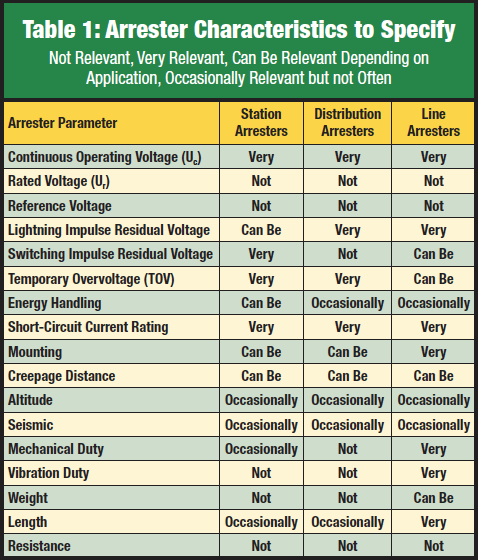
Table 1 outlines the important characteristics for IEC type arresters but can also be used to evaluate and specify IEEE certified arresters. However, terminologies may differ somewhat.
Station & Distribution Arresters
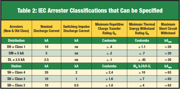
IEC 60099-4-2014 adopted the terms: ‘Station Arrester’ and ‘Distribution Arrester’, as seen in Table 2. In the past, these were referred to as High Voltage Arresters of Class 2, 3 or 4 or Medium Voltage Arresters. Both new terms were often used informally when specifying arresters but now are ‘official’ types of arresters.

Continuous Operating Voltage (Uc)
This characteristic is the most relevant voltage rating with respect to target applications and is defined by the operating duty test and TOV test series when the arrester was first designed and certified. When selecting an arrester for any application, this is a key parameter and should never be less than the phase-to-ground voltage of the system to which it is being applied. Continuous operating voltage should therefore always be included on purchasing specifications for all types and ratings of arresters.
Rated Voltage (Ur)
Although this voltage rating was important for the past generation of gapped silicon carbide type arresters, it has a much less relevance for MOV types. This characteristic is now the 10s power frequency overvoltage rating of the arrester, i.e. it is the arrester’s 10s TOV rating. If TOV is an issue for the target application, this value may become relevant along with other TOV levels. But apart from that, this parameter is no longer significant and this applies to all types of arresters, with the exception of externally gapped line arresters (EGLAs). The rated voltage of an EGLA is important, and is similar to Uc for other arrester types. In this case Ur is the maximum permissible continuous voltage of that arrester.
Reference Voltage (Uref)
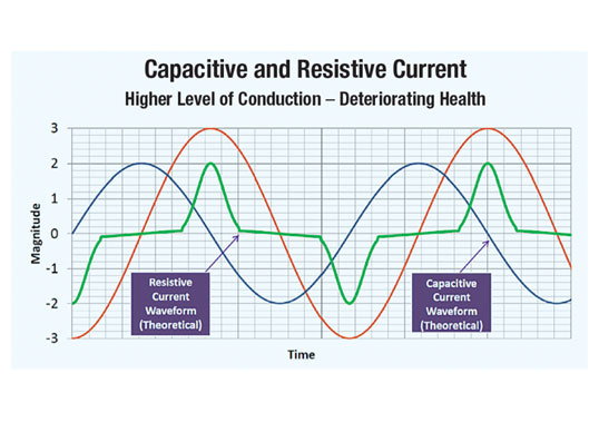
The reference voltage is defined as the rms voltage that appears across the arrester when a 1 to 10 mA peak current flows through it. This parameter is important for arrester designers and testing facilities but not really relevant in a purchase specification. The arrester Uc and TOV curve give all the information that is necessary to specify the arrester. Still, though not important when specifying an arrester, it is desirable to understand this characteristic.
The Uref for any arrester rating will vary from one manufacturer to the next, but all fall within a normal range of +5% to +25% above Uc. If Uref is not adequate or a specific design, it would be flagged during the arrester operating duty test since the thermal recovery phase would not be passed.
Absolute Uref is not as important as change in Uref with time due to high current impulses. Though this parameter is not usually published, it is verified not to change by more than 5% after the arrester is impulsed at its maximum withstand rating in the Repetitive Charge Transfer test, as per IEC 60099-4. These considerations apply to all non-gapped arrester types. For gapped arrester types, there is no Uref characteristic.
Lightning Impulse Protective Level at 10 kA (Upl) or Lightning Impulse Residual Voltage at In</b
Lightning impulse protective level is the reason an arrester needs to be properly specified since this is what users are paying for. As such, a value must be selected that will result in effective protection for the target insulation.
If the arrester is intended to protect e.g. a substation transformer that has low or aged insulation withstand levels, the lowest possible value of Upl should be specified. By contrast, if the transformer was purchased with high withstand capability, a higher level of residual voltage may also prove beneficial. To determine if the residual voltage is adequate, the Fast Front Protective Margin (FFPM) is calculated using Eq 1. If the result is greater than 15%, there is adequate lightning protection for the equipment.
Eq 1: FFPM = ((LIWV/Upl) -1) x 100(in percent)
For medium voltage systems where a distribution transformer is being protected, the same logic applies as in the above substation transformer calculation. The same is true for line arresters but in this case the insulation being protected is self-healing and flashover (or failure to withstand) is not critical. In this case, the Upl of the arrester should be compared to the U50 of the insulator using Eq. 1. If the margin is > 0%, there is adequate protection.
In all the cases above, if there is excessive lead length on the line or the ground lead of a distribution arrester, a more complex calculation is needed. Also, if the substation transformer and arrester are located more than 10 m apart, protective zone calculations need to be considered. In both cases, IEC 60099-5 provides a formula to make these calculations.

Switching Impulse Protective Level (Ups) or Switching Impulse Residual Voltage
This is an important parameter for arresters applied to systems above 245 kV. For systems below this voltage, the energy level and amplitude of switching surges are minor compared to the lightning surges the arresters are designed to protect against. Therefore, this parameter need only be specified for arresters with Uc higher than 144 kV.
For line arresters, if their Uc is more than 10% above that of arresters at the nearest substation, they are immune to switching surges. Here, only the station arresters will conduct during a switching surge. When selecting arresters for a distribution line, this parameter should never be specified unless there is a significant capacitor bank on the system that could result in a switching surge under certain energization schemes.
To determine if the Ups specified is appropriate for the power system, the slow front protective margin is calculated using Eq 2. In this case, the Ups is compared to the insulation’s switching impulse withstand voltage (SIWV).
Eq 2: SFPM = ((SIWV/Ups) -1) x 100 (in percent)
If SIWV is not known, the LIWV can be multiplied by 0.85 to yield an approximate value. An adequate margin for equipment protection is any value greater than 20%. For line arresters, a margin calculation value greater than 0 % is adequate. For distribution systems with capacitor banks, a margin of 20% or greater is adequate.
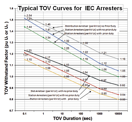
Temporary Overvoltage (TOV)
This characteristic of MOV type arresters did not exist for gapped silicon carbide arresters but has been quantified for years. Still, it only became a full parameter in the 2014 edition of 60099-4 as an actual test instead of normative annex.
Arresters are not designed to prevent or mitigate temporary overvoltages but are designed to survive these without damage. If an arrester with incorrect TOV withstand capability is applied to a system, it has a higher probability of premature failure.
Here, one can specify either the TOV characteristic curve shown in Fig. 1 or the worst possible TOV event. In either case, to determine what TOV characteristic to specify, it is necessary to first know the important parameters of the system to which it will be applied. Among these are the amplitude and duration of the worst-case overvoltage the arrester will experience. With this information, the user or supplier can determine what arrester is needed to survive such an event. The most straightforward specification is to indicate the time and amplitude of the worst case TOV in kVrms and seconds. For example, a specification can state that the arrester should have a 10 s withstand of at least 25 kVrms.
Suppliers often publish TOV characteristic curves in per unit (pu) of Uc or Ur. To use these curves to determine specific arrester TOV capability, it is necessary to convert from a pu to a kV basis. This is done by multiplying the chosen arrester Uc or Ur by the TOV factor on the characteristic curve. Then, the actual TOV scenario can be plotted on the same curve. Note: Prior duty only refers to a rated surge immediately prior to the TOV event without time to cool down.

Energy Handling
This characteristic of surge arresters changed considerably with publication of IEC 60099-4 Ed. 3.0 2014 and may not yet be familiar to those who specify arresters. In fact, these new parameters will be phased in by suppliers over the next few years. The main difference is that energy handling is no longer just a kJ/kV Uc value but is rather based now on both a thermal rating (Qth or Wth) and a repetitive charge transfer rating (Qrs).
Distribution Arresters
Distribution arrester duty is related only to lightning. This type of arrester does not typically experience high energy switching surges and therefore lightning duty is all that is taken into account during specification. However, if there are large capacitor banks on a distribution system, i.e. where MVar rating is approximately equal to kV rating of the system, station class arresters should be specified instead.
For areas where the ground flash density (GFD) is greater than 4 flashes/km2, DH arresters should be specified. Both energy handling parameters can be specified (as shown in Table 2) but specifying just arrester class should be adequate. For GFD levels below 5, DM or DL classes can be specified. It should be noted that since lightning is the only significant source of energy to distribution arresters, its thermal rating is measured in coulombs.
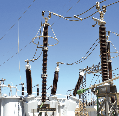
Station Arresters
Station arresters are divided into two ranges based on system voltage. For arresters applied to systems below 245 kV, lightning parameters are of most importance while for systems above this level, switching surge parameters are of primary importance.
Systems ≤ 245 kV Phase-to-Phase:
Thermal energy dissipation requirement and repetitive charge transfer withstand capability are minimal for these systems and Station Light (SL) type arresters are almost always sufficient. But if a system has a large installed shunt capacitor bank or a long underground cable in the circuit, higher energy capabilities may be necessary and SM or SH arresters should be specified.
IEC 60099-5 offers formulas that can be used to calculate required thermal energy dissipation. Per IEC 60099-4-2014, the Qrs rating of these arresters is given but the actual requirement is not yet available in IEC 60099-5. The lightning charge transfer rating Qrs (lightning) of this arrester is not specified in the test standard but a formula to calculate it can be found in IEC 60099-5.
Systems > 245 kV Phase-to-Phase:
Depending on length of a line, thermal energy rating can be very low or very high. The energy requirement should be determined by a switching study or can be approximated from formulas found in IEC 60099-5. For lines > 245 kV, SH and SM type arresters are usually specified.
Transmission Line Arresters:
All line arresters are subject to lightning, either directly or shared with the OHGW. If the Uc of a line arrester is equal to that of station arresters on the line, they can also be subject to switching surges on systems above 245 kV.
If a line arrester is applied to an unshielded system, the Qrs and Qth levels are usually higher then DH class arresters. In this case, SL or even SM class arresters need to be specified. It is strongly recommended that system studies be completed on all line arrester installations without OHGW. If a system is shielded, DH class line arresters are to be specified.
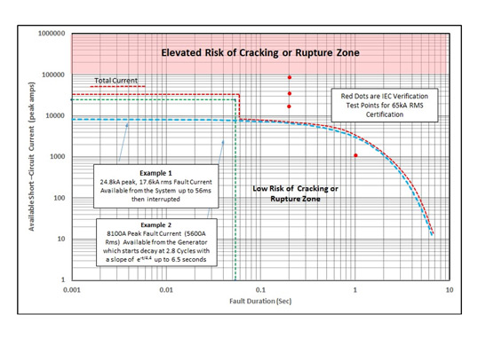
Short-Circuit Current Withstand
Although this arrester specification has not changed much in years, there is still misunderstanding when determining what to specify. The IEC application guide, for example, is vague on how to specify this parameter, therefore Figure 2 is offered for clarification.
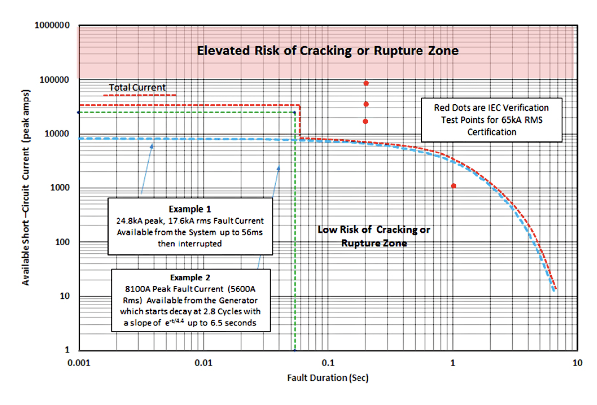
When specifying short-circuit withstand capability, all sources of short circuit current are to be added together. Total available short circuit current should not exceed the nameplate rating of the arrester. Duration of the fault is not relevant, only amplitude. Also, care must be taken that all current amplitudes used in the analysis are either peak current or rms current and do not mix the units. This method of specification applies to all types of arresters.
Mounting
Mounting is a flexible specification for most arresters and the only time limits are applied are for arresters with Uc above 150 kV. For arresters above this level, each manufacturer has its own specifications. Horizontal mounting can stress the mechanical strength for the higher ratings but electrical parameters are not affected by this option. If an arrester is to be underhung from a cross member, it is necessary to ensure that sheds do not collect water. This mounting specification is true as well for distribution arresters.
Transmission line arresters are subject to numerous forces not typically experienced by other arresters and therefore mounting specifications are particularly important. If there is a ground lead disconnector as part of the TLA installation, the mounting method must not overstress it. Also, ground lead disconnectors must have ample room to disconnect without making contact with other phases.
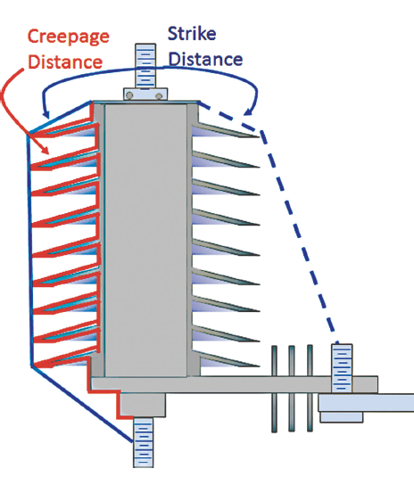
Creepage Distance
Creepage distance can be a critical parameter depending on where the arrester is located and the types of service conditions to which it will be exposed. If the creepage distance of insulators in the immediate locations have a 50% increase over standard insulators, then that same factor should be used for the arresters.
The most common reason for extended creepage specification is where there is high salt fog or salt contamination in the service area. However, care must be taken not to specify excessive creepage simply because every cm of distance longer than actually needed for the application unnecessarily raises acquisition cost.
(U50, BIL or CFO)
This parameter has no place in any arrester specification, unless the application is located above 1000 m. Arresters do not flashover from lightning surges. Moreover, since they contain internal MOV disks, arresters always clamp the voltage below a level that could cause flashover, i.e. they are self-protected with infinite impulse withstand when installed below 1000 m altitude.
Altitude
All IEC certified arresters are designed for applications up to 1000 m. If an arrester is to be applied above that height, strike distance and creepage distance both need to be increased. For every increment of 100 m above 1000 m, strike and creepage dimensions must be increased by 1.2%.
Seismic
There is no IEC standard that specifies seismic requirements for arresters and IEEE 693 can be used as a reference for this parameter. If the application is located in a region with high seismic activity, this standard will offer the parameters that must be specified to ensure a safe arrester installation.
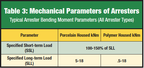
Mechanical Duty
When installed, arresters are expected to withstand many forces, but those that are usually most severe are when the attached lead experiences short-circuit currents past the arrester. Should this occur, significant cantilever forces can be applied at the base. Each arrester is therefore tested to withstand such forces in bending moment tests. Arresters are not designed nor tested for torsional strength, other than for normal installation forces.
Resistance
Specifying resistance of an arrester is not recommended. Measuring resistance with a low voltage megger is inaccurate and such devices will yield erroneous data. If an arrester is failed, this can be detected by a megger and, as such, this can be done upon installation. The resistance of a good arrester measured with a Megger is infinity +/- .5 infinity – in other words, almost anything extremely high. Specifying such a value is not a good idea.