About 20 million composite line insulators are already in service on HVAC overhead lines all over the world. Moreover, the growth in market penetration of this technology seems exponential.
The first installations were in Germany in 1967, predominantly in areas of industrial pollution, and in the Netherlands in applications where there was coastal pollution. As such, the service record for AC line composite insulators now covers more than 40 years.
Line composite insulators were adopted for DC use about 10 years later than for AC. However the level of overall service experience in DC is much lower, due mainly to the fact that the number of DC lines are comparatively much less than AC. At the same time, the potential advantages of such insulators for DC are much greater because the main dimensioning factor in DC is pollution performance. Here, composite insulators offer superior performance in comparison to insulators made of glass or porcelain.
At the same time, optimally dimensioned DC composite insulators clearly need to be verified in regard to ageing. This article from 2011, contributed by Igor Gutman, Kjell Halsan of Statnett (Norway), Wallace Vosloo of Eskom (South Africa) and Jens Seifert (Germany) evaluated pollution and ageing performance of DC composite insulators with emphasis on field experience and how it compared with laboratory test experience.

Service Experience
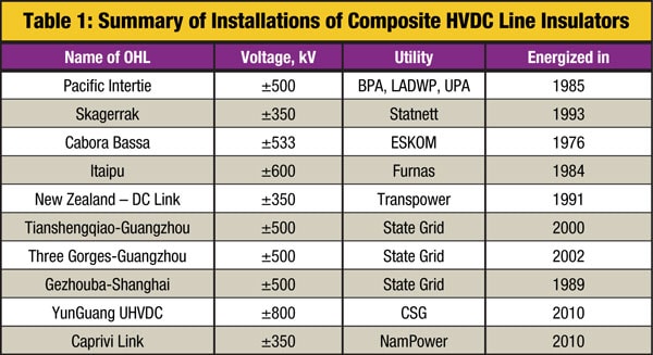
Based on the recent discussions within CIGRE/IEC, a worldwide list of the HVDC overhead lines (OHL) equipped with composite insulators is as follows (see Table 1 and details on some installations below)
Skagerrak
Composite insulators from four manufacturers were installed for testing purposes in 1994 on the Skagerrak III ± 350 kV DC link in Norway. These were subsequently inspected at STRI in 2008. The service environment was comparatively clean at the time of inspection (ESDD=0.002 mg/cm2).
The creepage distance of the composite insulators installed for more than 15 years on different DC poles in Norway were in the range 27-41 mm/kV while the corresponding specific creepage distance of glass cap & pin insulators was 46 mm/kV.
Service experience was excellent. No flashovers were reported during the line’s operation, even for insulators with a specific creepage of as little as 27 mm/kV.
CLICK TO ENLARGE
Cabora Bassa
Composite insulators from several suppliers were installed on the ± 533 kV Cabora Bassa-Apollo HVDC line in South Africa. Insulators from two of these manufacturers were tested in 2009 after 17 years in operation. The environment at Cabora Bassa is light to medium pollution. At the time of inspection, the maximum ESDD/NSDD values were 0.04/0.6 mg/cm2. The creepage distances of the composite insulators were in the range of 29-33 mm/kV while the corresponding specific creepage distance of glass cap & pin insulators was 23-27 mm/kV. No flashovers were recorded among the composite insulators tested.
CLICK TO ENLARGE
CLICK TO ENLARGE
Pacific Intertie
Composite insulators were installed on the ± 500 kV U.S. Pacific Intertie HVDC line. Prior to 1984, the line was operated only at ± 400 kV using glass and porcelain cap & pin insulators. Yet it frequently tripped out due to flashovers, especially in the heavy pollution near Los Angeles, even at the reduced voltage.

In 1984, silicone rubber insulators were first installed and a year later the line voltage was finally uprated to its design value of ± 500 kV. After installation of the silicone insulators, no pollution flashovers were recorded during the past 27 years. Due to this excellent experience, the line was eventually fully equipped with silicone insulators.
The L.A. utility, LADWAP, performed ESDD measurements on reference cap & pin insulators and found these to fall in the range of 0.03 to 0.04 mg/cm². The composite insulators that have performed well in this environment have a specific creepage distance of 26 mm/kV. (Note: After design re-calculation, this happens to coincide with the value derived from STRI’s Insulator Selection Tool software for this ESDD range).
In 2001, several insulators were taken down for an inspection conducted by an independent laboratory contracted by LADWAP. The results showed no traces of ageing nor of any corrosion (the latter having been a frequent problem for the previous cap & pin insulators). A further inspection combined with pollution testing of some of these units would probably be of great value to study the longterm electrical insulation performance and derive data for standardization of creepage distance at such a voltage.

Itaipu
Several so-called ‘first generation’ composite insulators with a specific creepage of 22 mm/kV were installed for testing purposes on the ± 600 kV Itaipu line in Brazil. No flashovers of these insulators were recorded during 18 years of operation and they were subsequently inspected and tested at the CEPEL laboratory.

CLICK TO ENLARGE
Summary of After-Service Testing
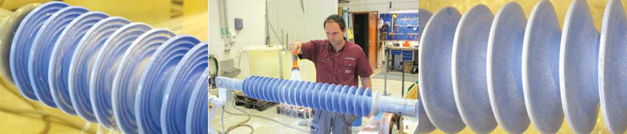
A number of diagnostic after-service tests were performed on the insulators used at Skagerrak and Cabora Bassa. Most were performed at STRI, however some material tests of the Skagerrak insulators took place in South Africa while tests of Cabora Bassa insulators were performed in Germany. The latter were conducted in accordance with IEC 61109 and IEC TR 62039 as well as the material and product specifications of the insulator manufacturer.
Based on investigating ageing, comprising visual inspection, pollution measurements, material tests, observations of hydrophobicity supplemented by voltage tests of complete insulators with simultaneous UV and IR observations, no signs of deterioration could be observed. From investigating pollution performance, utilizing tests of naturally polluted insulators at elevated voltage and artificial pollution tests, with and without recovery of hydrophobicity, it was found that the dielectric strength of the insulators under pollution had not decreased.
Evaluation of Ageing Performance
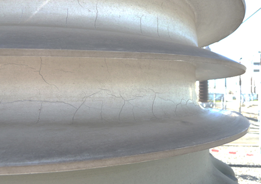
None of the insulators studied showed any visible signs of deterioration from service. Whatever deterioration was observed had originated from handling, most likely during their removal from the line and transport from the site. However, none of these were considered serious enough to have any negative impact on performance or expected service life.
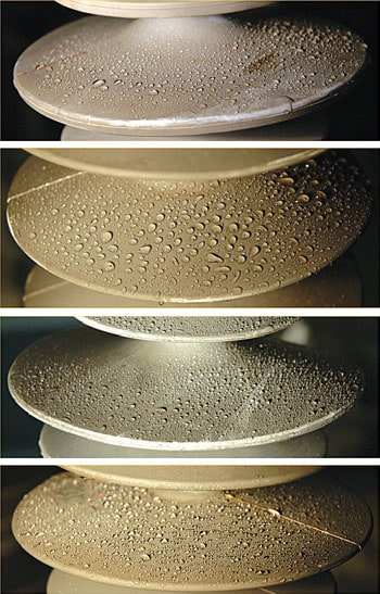
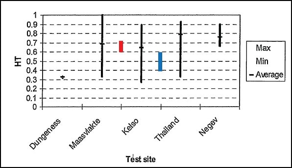
At the time of inspection, all insulators removed from Skagerrak, Cabora Bassa and Itaipu were still highly hydrophobic, with wettability class (WC) 1-2 on the top side of sheds.
The Hydrophobicity Transfer (HT) was calculated from Apparent Salt Deposit Density (ASDD), which in turn was accessed via the resistance of a waterfilled test cell placed on the insulator surface. The results were in line with earlier results obtained on silicone AC apparatus insulators.
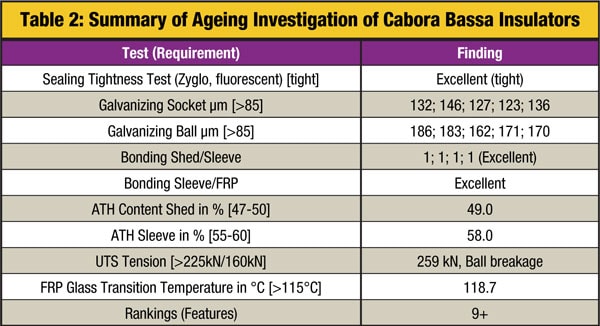
A series of tests (see Table 2) were performed on insulators from the Cabora Bassa line in order to study any ageing of the units and of their component materials. None was observed. The materials and the design both still passed all the original product specifications as well as the relevant IEC standards.
Evaluation of Pollution Performance
Naturally Polluted Insulators Removed from Service
All composite insulators removed from Skagerrak and Cabora Bassa were subjected to a modified clean fog test under natural pollution. Tests were performed with steam fog application to insulators energized at 2 p.u. voltage applied for 1 hour. This is equivalent to 500 kV and 700 kV for Skagerrak insulators and 1066 kV for Cabora Bassa insulators.
Maximum recorded leakage currents were very low (i.e. in the range 1 to 5 mA) throughout the test. Current levels were considered absolutely non-critical even though the applied voltage was twice as high as the service voltage. The risk of flashover in service at this level of pollution was considered virtually negligible.
CLICK TO ENLARGE
Artifically Polluted Insulators Removed from Service
Because only one test object of each type was available from service, it would have been too time consuming to use the standard procedure of the ‘up-and-down’ test to obtain U50% flashover voltage. As such, the socalled Rapid Flashover Clean Fog Test Method was applied. This is now becoming a more and more attractive alternative to standard procedures.

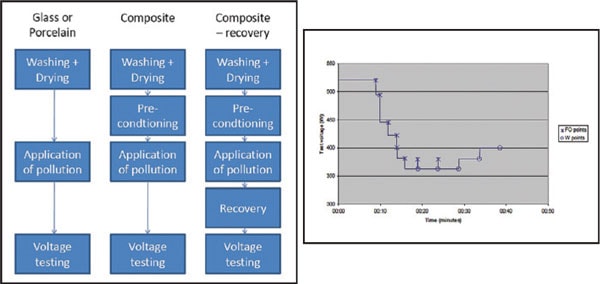
According to this test methodology, the polluted insulator is simultaneously exposed to fog and voltage, while the latter is changed stepwise in order to identify the minimum flashover voltage. Consequently, only one test is required per insulator, level of pollution and degree of hydrophobicity. Since it is virtually impossible to obtain a uniform layer of pollution on hydrophobic composite insulators, a special procedure accepted within CIGRE was applied for pre-conditioning and testing. To assess recovery of their hydrophobic properties, composite insulators were tested directly after contamination and again after 2 days between the contamination and the voltage test. A recovery time of about 2 days seemed reasonable from the service point of view as a typical period between a pollution event and any subsequent wetting.
• The Rapid Flashover Clean Fog procedure details applied for the tests was as follows:
• Initial time between application of steam fog and the first voltage was chosen as 15 minutes based on analysis of previous tests;
• Voltage step was chosen to be about 5% of inspected U50% voltage;
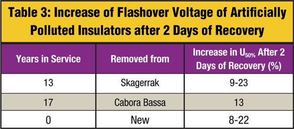
Duration of one voltage step was chosen as 5 minutes.The results, presented in Table 3, show that, after two days of recovery, the flashover voltage of ‘aged’ insulators would increase approximately 10 to 25% depending on type of insulator (most probably on type of silicone rubber). This is approximately the same as for new insulators tested in the frame of the CIGRE Round Robin Test (RRT). Therefore, the insulator material is clearly still working as ‘reservoir’ for low molecular weight components that guarantees high flashover voltage under polluted conditions.
Summary of DC Laboratory Pollution Tests on New Insulators
It is generally agreed that standardized laboratory test methods are not suited for use on composite insulators. However, the Modified Solid Layer test method shown earlier is under consideration by CIGRE and indeed was recommended for a related AC Round Robin Test. A similar test procedure was applied at STRI for DC testing of a silicone insulator.
CLICK TO ENLARGE
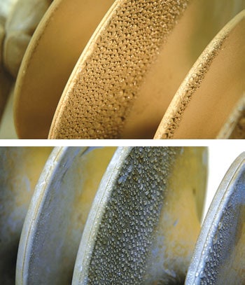
After pre-conditioning to mask hydrophobicity of the composite insulators sufficiently, a standard spraying method could be used to apply the pollution layer. The insulator was then mounted horizontally in a rig and was rotated at 5 to 10 revolutions per minute while the slurry was applied evenly with a spray nozzle. The insulator was then left to dry at room temperature before being tested the next day.
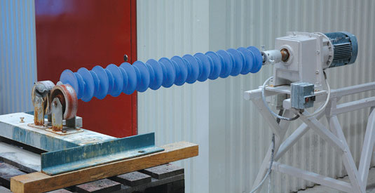
CLICK TO ENLARGE
Voltage tests were performed in accordance with the procedure prescribed for the Solid Layer Test in the standard applicable to ceramic insulators, i.e. IEC 60507. The ‘upand- down’ test method was used to obtain the U50% flashover voltages and each voltage test was performed on a ‘new’ polluted insulator.
After finishing the first series of tests without recovery of hydrophobicity, the insulators were polluted in the same way, but left for 2 days before the voltage test. All tests were performed using a voltage of negative polarity and, in the case of the ‘up-and-down’ procedure, a voltage step of about 6% was applied.
Discussion: Service Experience vs. Laboratory Experience
Pollution Performance
Experience from Skagerrak, Cabora Bassa, Itaipu and the Pacific Intertie has clearly shown that no pollution flashovers were observed on installed composite insulators during up to 18 years of service. Moreover, it was suggested that composite insulators could, on average, be from 24 to 34% shorter than glass strings in the same service environment.
CLICK TO ENLARGE
CLICK TO ENLARGE
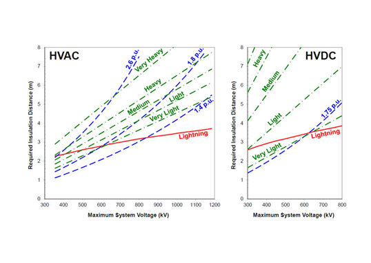
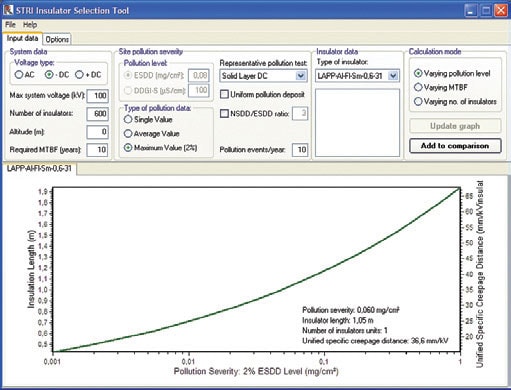
The feasibility of using laboratory DC pollution performance testing for insulator dimensioning was also analyzed. Laboratory data in the form of U50% as a function of SDD was the input used in the STRI Insulation Selection Tool (IST) program to estimate required insulator dimensions for DC lines in Norway. An ESDD level of 0.06 mg/cm2 was considered the most typical for Norwegian conditions and this yielded a required insulator length of 1.05 m.
The results obtained were consistent with other laboratory studies recently performed at STRI. For the same pollution severity conditions (i.e. 0.06 mg/cm2), the length of composite insulator recommended per 100 kV DC is 1.13 m, while the proposed length of a glass cap & pin insulator string per 100 kV DC is 1.4 m. Therefore, the insulator tested could be 1.05/1.40 = 0.75, i.e. 25% shorter. This is in line with service experience in China, where the creepage distance of composite insulators is typically specified at about 75% of equivalent ceramic strings.
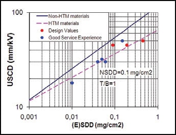
Therefore, in regard to pollution performance, it seems feasible to use laboratory data for DC dimensioning. This is supported by recent progress during CIGRE/IEC discussions, where ‘average’ laboratory curves for glass and composite insulators are related to service experience. Here, it is seen that existing service-related data (dots) is quite similar to averaged laboratory results (lines).
Ageing Performance
Service experience from both Skagerrak and Cabora Bassa confirm that no deterioration took place on composite insulators installed on those lines for periods of up to 18 years. After-service tests have also confirmed that, from a hydrophobicity point of view, the insulators removed were still as good as new. It can be assumed that, in general, service experience with composite insulators on DC lines is relatively more positive (even if far more limited) compared with on AC lines.
Summary
1. Field experience and tests on silicone rubber insulators removed from 13 to 17 years of service on DC lines in light to medium pollution environments has shown that their condition and pollution performance is still excellent. Especially important for such insulators is their ability to recover hydrophobicity. This aspect was directly measured by means of their increase in flashover voltage under polluted conditions and was determined to be approximately the same as for new insulators.
2. Laboratory pollution flashover tests at DC using the modified Solid Layer Test method (both the rapid and the up-and-down procedures) are valid for dimensioning purposes. These results are consistent with existing service experience.
3. The common practice of laboratory DC tracking & erosion tests (at the same stress as rms for AC) can lead to overly conservative conclusions on ageing performance when one considers all the positive service experience. It is therefore recommended that the DC test stress be reduced and that multi-stress test methods be used instead to simulate recovery of hydrophobicity.