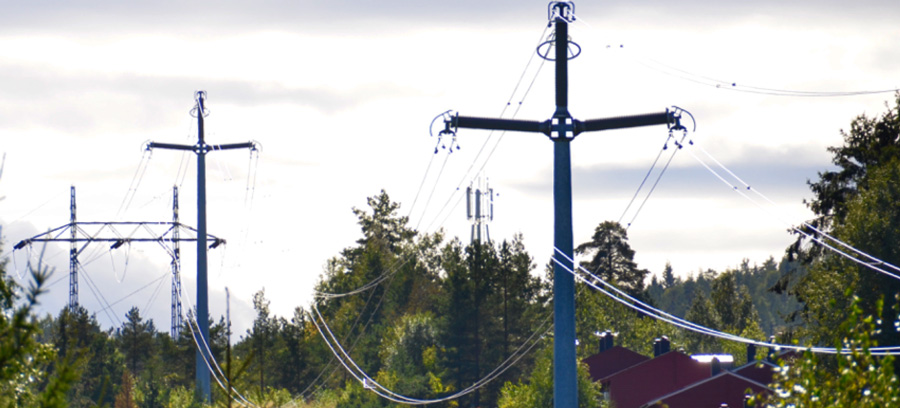
Designing a 420 kV line that meets the strict criteria needed to be acceptable to those living in urban and suburban communities presents a serious challenge. These criteria include relatively narrow corridor, low visual impact, high aesthetic appeal as well as reduced electromagnetic field and audible noise – all the while also meeting basic performance requirements such as sufficient lighting protection.
By the early 2000s, this challenge had already been considered by TSOs in Nordic Europe, who were facing an increasingly difficult task obtaining new right-of-ways. Specifically, these network operators wished to identify alternatives to laying expensive cable when upgrading transmission lines that pass sensitive population centers.

The first prototype structure developed and built to support this conductor arrangement was dictated largely by the types of insulators available during the 1990s. This structure was an unwieldy design that relied on tension strings employing composite long rod insulators. The prototype had a total height of 19 meters with an additional 2.5 m added by the arrester at the top of the pole. Since earth wires had to be eliminated to achieve the desired compaction, a transmission line arrester with a polymeric housing was also designed into the structure. Ultimately, while this design met most basic criteria, it became obvious that such a structure had too many parts and was not suitable from an aesthetic viewpoint. In addition, it would be costly to build since each string span would have to be tensioned individually.
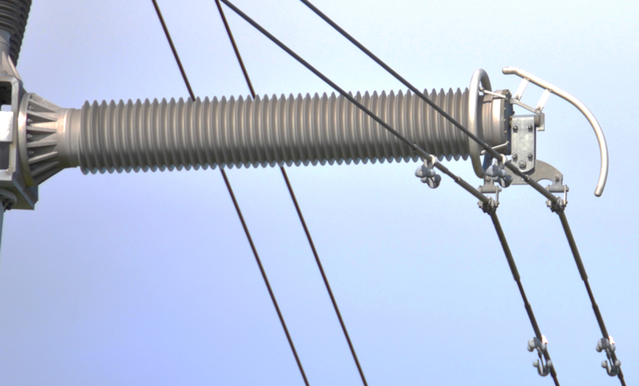
Around that same time, developments in hollow composite insulators were progressing and soon reached the stage where customized composite post insulators having high mechanical strength yet relatively low weight could be supplied. The updated compact design that became a reality on a test span at STRI in Sweden by 2001 incorporated a trio of hollow core insulators that utilized special foam to fill the space within their inner FRP tubes. Given the horizontal configuration of these insulators, it became necessary to increase the original optimized conductor phase spacing of 5 m to either 5.4 m or 6.4 m in order to account for the modified air gap between conductor and structure.
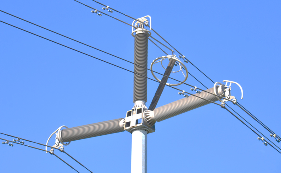
The hollow composite post insulators utilized in this design were of two types: a vertical unit with mechanical strength of 148 kN and total creepage of 8600 mm; and two identical horizontal post insulators of 50 kN and circa 8000 mm creepage. The reason for the significantly higher mechanical bending strength required of the vertical unit was that this type of design has to withstand relatively high bending forces whenever a line changes direction.
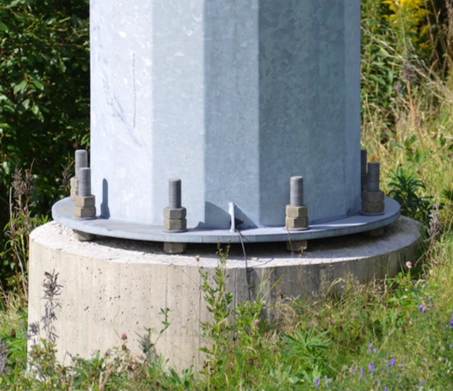
While these post insulators were expensive, each was intended to replace several tension insulators, meaning that the higher cost could be justified. Equally important was the fact that construction costs with this design are significantly reduced since the entire insulator and arrester section can be assembled on the ground and hoisted into place as a single unit. Also, only one flange is needed to attach the entire assembly to the supporting structure – in this case a steel pole but which could be any type of structure desired.

By eliminating the uppermost support insulator of the original prototype, the modified design offered total structure height of only 19 meters – by any measure low visual impact for a 400 kV line. It was also designed to handle maximum ice loads of 4 kg/m, considered acceptable for most sheltered environments, even in Norway. Span length of the new design was between 200 and 250 m depending on service conditions such as wind and ice. The shorter range would apply more to areas where ice loads are higher than 4 kg/m or wind speeds are up to 28 m/s.

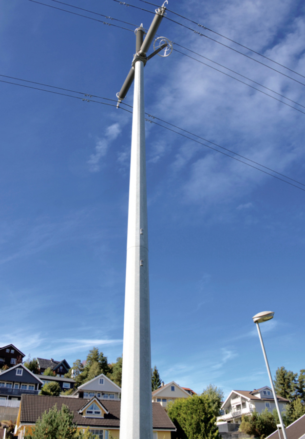
Reviewing the advantages and drawbacks of this compact design, developers noted that it was not intended to replace conventional long distance transmission. Rather, it was to be applied only in areas considered sensitive from an environmental perspective or where there are restrictions in terms of available line corridor. It is also much less costly than cables for suburban areas where permission cannot be obtained to build conventional lattice structures. Another benefit is that electromagnetic field with this design is only some 40 per cent of what is normally encountered on conventional lines at this voltage. Similarly, right-of-way needed is only a third of the 18 m width generally required – a reduction of 12 m. Finally, simple installation with mounting of the entire pre-assembled superstructure onto the pole offers savings as well.

This design allows the same outage rate as a conventional line when utilized over short segments, achieved by employing polymeric-housed TLSAs in place of earth wires. These arresters are mounted using a special device so that, if any energy surge encountered is too great, they disconnect from the conductor. Visual line inspection can then readily determine that they need to be replaced, even though the line remains in service. Notwithstanding this feature, the design is not ideal for areas with heavy lightning.