The largest clean energy project in U.S. history – the SunZia Wind & Transmission Project – includes a 550 mile ±525kV HVDC line connecting the States of New Mexico and Arizona. One of the most critical elements of this Project involved developing applicable specifications and testing for this line’s transmission assemblies and components.
This edited contribution to INMR by Jeff Butler of Hubbell Power Systems, which played a key role in providing guidance to the Design Engineering Team, explains how testing for these was defined to ensure performance would meet the Project’s demanding requirements.
Spanning almost two decades of planning and development, the SunZia Wind & Transmission Project marks a landmark in development of the clean energy sector in the U.S. The project included construction of over 500,000 acres (810 km2) of generation consisting of over 900 windmills integrated to the grid with a 550 mile ±525kV HVDC transmission line. This line provides connection of generation assets in New Mexico to central Arizona load centers (see Fig. 1). With an investment exceeding $10 billion, the scope of the project includes servicing over 1 million American homes, making it the largest clean energy infrastructure project in the country’s history. Once fully operational in 2026, this Project will set a standard for other large-scale renewable energy projects.
One of the key elements of the Project is the ±525kV HVDC Transmission Line which will serve as a major artery for clean energy distribution across the southwest. A critical focus in project success was developing an effective test plan for key components and materials of the line, namely the transmission assemblies which included insulators and hardware.
In this regard, steps were taken to evaluate applicable standards from ANSI, IEEE and IEC that guide electrical and mechanical testing of products under high voltage transmission applications. However, since testing for HVDC is still not comprehensively defined, one of the challenges involved applying available standards to develop a test plan to verify performance.
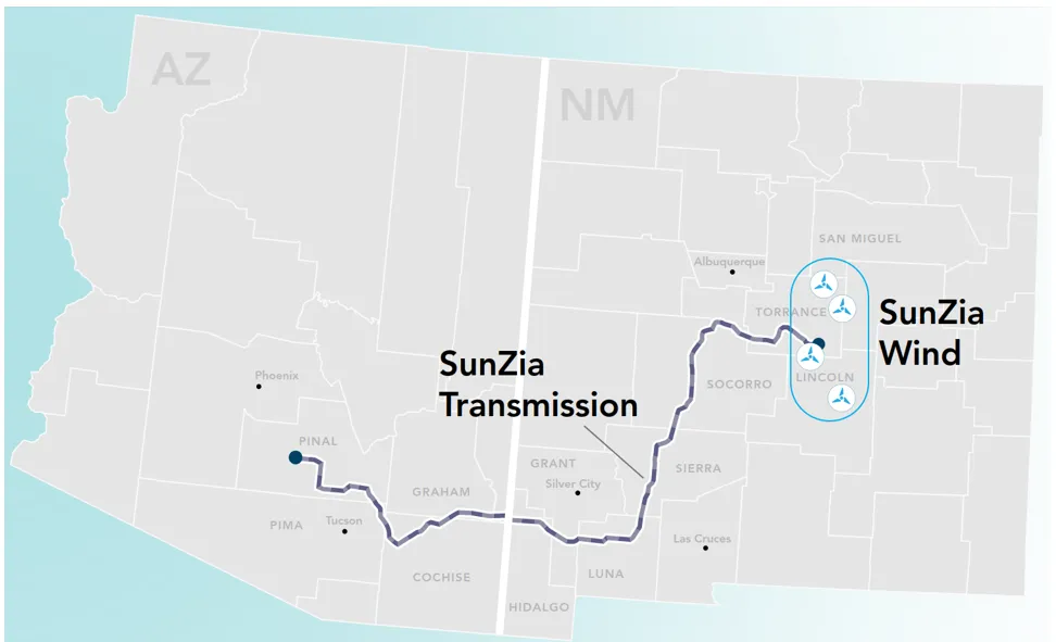
(image source: SunZia Project Fact Sheet – downloaded from website: https://patternenergy.com/projects/sunzia/)
SunZia Transmission Line Design
The SunZia Transmission Line Project consists of a 550 mile ±525kV high voltage direct current (HVDC) transmission line connecting central New Mexico to south-central Arizona. This line will have a capacity to transport up to 3,500 MW with the expectation to provide power to over 1 million American homes.
The transmission line design is a bi-pole design using pole conductors in combination with metallic return conductors. Structure designs included both tubular steel and lattice towers, depending on requirements and related assembly designs, as detailed in Table 1.
SunZia Transmission Line Testing
1. Evaluation of Relevant Industry Standards
Given the importance and scope of the Project, it was necessary to consider existing guidance and standards to evaluate performance of key components. However, as stated, there is still only limited guidance defined in available industry standards. Therefore, an investigation was performed to determine applicable current standards and how these could lead to a relevant test plan.
2. Results
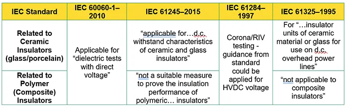
An analysis of relevant IEC standards was performed (see Table 2). This uncovered a lack of clarity in terms of defining effective testing for polymer insulators for HVDC applications. Certain standards define they are not applicable for polymer/composite insulators but do not provide sufficient clarity as to whether this exclusion is intentional or accidental. There is guidance from IEC 61109-2008 “Insulators for overhead lines – Composite suspension and tension insulators for a.c. systems with a nominal voltage greater than 1 000 V – Definitions, test methods, and acceptance criteria”. However, despite the name of this standard referencing a.c. systems, the standard references procedures for electrical tests with the following:
“The electrical tests… shall be performed according to IEC 60383-2 to confirm the specified values.”
In referencing IEC 60383-2–1993, the standard states in “Section 2: Test procedures for electrical tests” that “[t]he lightning and switching impulse voltage and power-frequency voltage test methods shall be in accordance with IEC 60-1.” While impulse voltage is agnostic to whether it is for an AC or DC system, it was still important to apply available guidance from the standards in support of a proper test plan. Therefore, in an indirect but logical path, IEC 61109 states that it only applies to “a.c. systems” but then references IEC 60060-1 that does allow for direct voltage tests. Similar evaluations of relevant standards provided some guidance toward a proper test plan.

3. Transmission Assembly Material Testing
As applicable standards were evaluated, a test plan began to unfold. For glass bells, the standards provide clear guidance on HVDC testing. However, they do not provide such guidance for polymer/composite insulators. On the other hand, the standards relevant to transmission hardware testing are more direct with little distinction necessary for AC vs. DC since testing is largely mechanical or current based. Based on these reviews, the following testing outlines the particularities for insulators and assemblies specific to the challenges of HVDC and this project’s design.
A. Polymer Insulator Testing
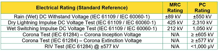
Minor but important adjustments from the defined standards were needed to define the electrical testing needs for the polymer insulators. As the defined ratings for insulators were developed it was necessary to perform the testing to confirm the insulators provided would meet these ratings (see Table 3).
1. Electrical Testing: Polymer Insulators
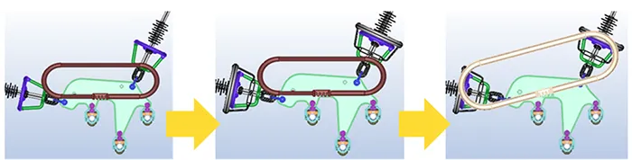
The polymer insulator designs were selected with the expectation to meet the electrical requirements of the Project. However, it was necessary to use a software package to perform electric field analysis (EFA) to evaluate corona performance of the entire assemblies. Simulations showed that optimal protection would be provided by a non-standard corona ring due to the challenges of the applied HVDC voltage that the assemblies would need to endure. This analysis led to development of a patent-pending combination ring design used on the polymer insulators for the PC assemblies (see Fig. 2).
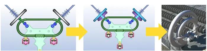
Moreover, evaluation of the design of the medium angle assembly resulted in optimal placement of the yoke plate mounted ring (see Fig. 3).
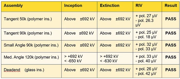
Insulator testing was conducted to verify the electrical ratings of the polymer insulators used on the project. The Metallic Return Conductor (MRC) polymer insulators were set-up as shown in Fig. 4 while the Pole Conductor (PC) polymer insulators were set-up as shown in Fig. 5. The PC polymer insulators were tested using the combination ring as determined from electric field simulation (see Fig. 2). The insulator assemblies were also set up as shown in Fig. 6 to evaluate corona performance. All insulators and assemblies met the ratings, as defined in Table 3.
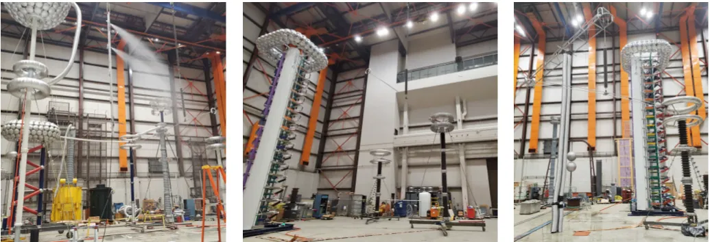
(Wet withstand – left, Dry impulse – center, Wet switching – right).
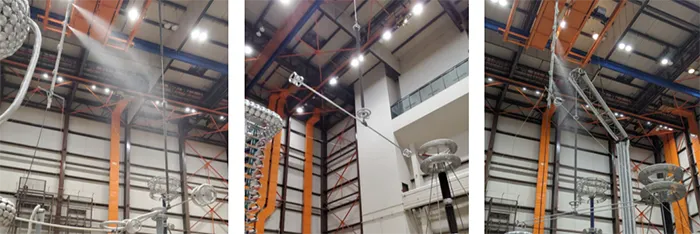
(Wet withstand – left, Dry impulse – center, Wet switching – right).
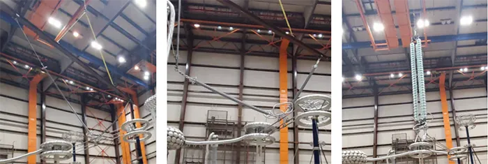
(Tangent assembly – left, Angle assembly – center, Deadend assembly – right).

The assemblies were also tested for corona/RIV values as defined per IEC 61284. The assemblies were tested without addition of the combination ring on the polymer insulators, as determined from e-field analysis, in order to evaluate the worst-case scenario for the assemblies. All assemblies met the requirements of the project for corona and RIV performance (see Table 4).
2. Mechanical Testing – Polymer Insulators & Assembly Testing
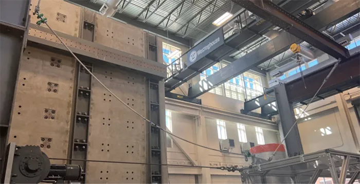
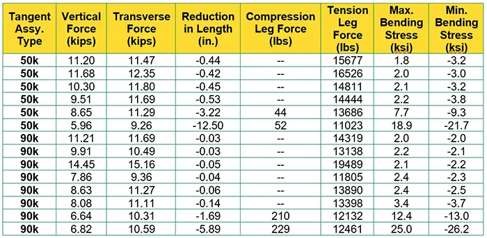
A test plan was developed to evaluate extreme wind loading on the tangent assemblies to determine if sufficient compressive load might be applied to the insulators that could compromise their mechanical integrity. The tangent assemblies for both 50k lbs. and 90k lbs. were mounted in the laboratory to apply a transverse load equivalent to the Project’s wind loading (see Fig. 7). The displacement, stress, and mechanical load of the insulator legs was recorded (see Table 4).
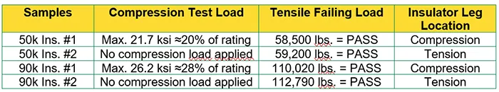
Finally, a tensile test to failure served to confirm that no impact was observed to the ultimate strength of the insulator in each leg of the assembly based on an estimated maximum stress for the fiberglass rod of ~100,000 psi (see Table 5).

Testing Silicone Rubber Compound
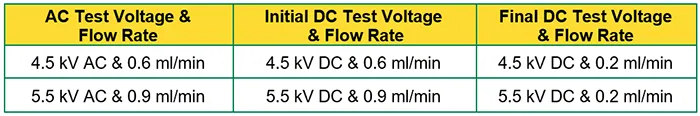
Testing defined in IEC 60587-2022 was used as the basis to develop a test method to evaluate performance of the polymer material relative to high voltage DC exposure. IEC 60587 defines an inclined plane test conducted on polymer plaque samples with applied voltage and contaminant flow to define a rate. However, since the standard does not differentiate between AC and DC applications, initial testing held the voltage and flow-rates constant for both AC and DC voltages (see Table 7).
Findings presented by CIGRE D1.27 evaluated effectiveness of the test method per IEC 60587 for AC and DC applications. In addition, the CIGRE D1.27 investigation was influenced by work in the Chinese Standard, DC/T 810-2002. One of the key outcomes of both efforts was to recommend that a flow rate of 0.2 ml/min be used for 4.5 kV and 5.5 kV DC voltages (see Table 7).
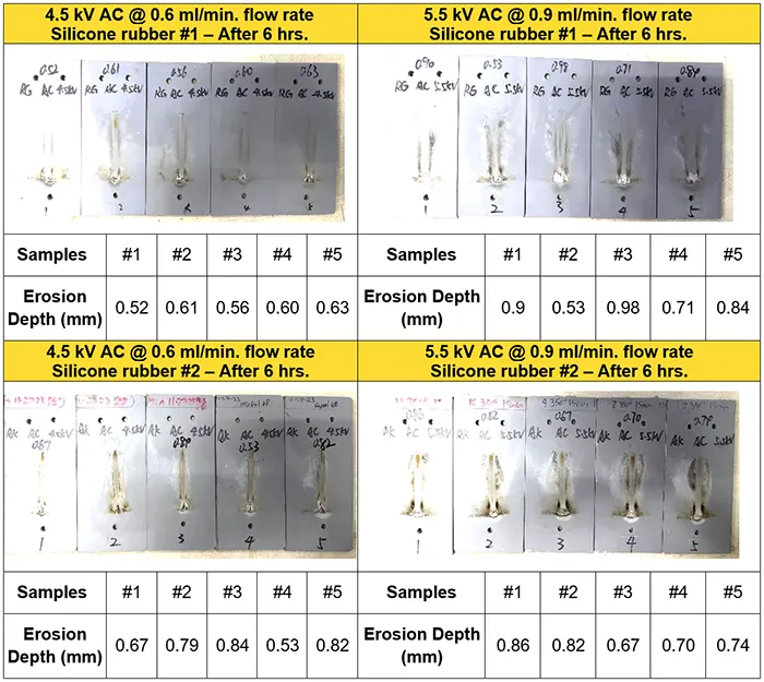
These test methods were evaluated with two proprietary silicone rubber polymer compounds offered. The samples passed testing for AC voltage, with visible erosion depth <1mm (see Table 8).

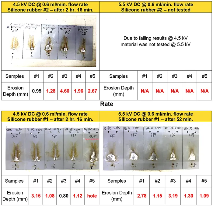
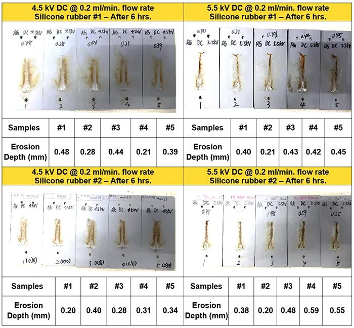
However, the same silicone rubber polymer compound samples failed the DC tests since erosion exceeded the maximum depth of 1 mm (see Table 9). These results aligned with findings from CIGRE D1.27 that a same flow rate for AC voltage is too aggressive for DC voltage testing. Therefore, based on these findings (and confirmed by CIGRE efforts and established Chinese standard), flow rate was reduced to 0.2 ml/min. Testing was then repeated on the two variants of silicone rubber compound at both 4.5 kV and 5.5 kV, this time with successful results (see Table 10).
These results confirmed the findings of CIGRE D1.27 that recommended flow rate for DC voltage for the IEC 60587 testing should be 0.2 ml/min to effectively evaluate performance of a silicone rubber compound, similar with the same test for AC voltage.

Conclusions
As this Project nears completion, with energization anticipated in 2026, its success has been due to the collaborative efforts of numerous stakeholders. This confirms the importance of early commitment to clear communication and disciplined focus toward a shared objective.
Despite challenges encountered, testing and evaluation of the transmission assemblies represented just one of several key milestones contributing to the overall achievement of this endeavor. As the industry continues to pursue HVDC projects of similar scale and complexity, it will be essential to establish clear, effective standards for testing to evaluate performance of critical components.
Bibliography
[1] SunZia Wind & Transmission – Fact Sheet [Internet]. [updated 2023 October; cited 2025 May]. Available from: https://patternenergy.com/wp-content/uploads/2023/10/20231005-SunZia-PROJECTS-Factsheet.pdf
[2] SunZia Wind & Transmission [Internet]. [cited 2025 May]. Available from: https://patternenergy.com/projects/sunzia/
[3] SunZia Transmission Project, US [Internet]. [updated 2024 July; cited 2025 May]. Available from: https://www.power-technology.com/projects/sunzia-transmission-project-us/?cf-view
[4] IEC 61109–2008
[5] IEC 60383–2–1993
[6] IEC 60060–1–2010
[7] IEC 61245–2015
[8] IEC 61325–1995
[9] Articulation and Bending Stress on V-String Long Rod Composite Assemblies. EPRI, Palo Alto, CA: 2024. EPRI Project 1-118633-01-01.
[10] IEC 60587–2022
[11] CIGRE D1.27-2015 – CIGRE Technical Brochure «Feasibility Study for a DC Tracking & Erosion Test.