The cable market is one of the ‘hot’ sectors in the transition to clean energy, with high demand for submarine cables resulting in back orders of from 2 to 5 years. Moreover, the consequences of climate change are also pushing growing application of underground cable networks since these are more resilient to the new risks. HVDC cable systems are used worldwide to carry high power over long distances as well as in situations where HVAC connections are either not feasible or not cost-effective. The interconnector market, for example, is expected to grow over the next decade to develop greater flexibility in grid systems, raise cross-border electricity trading and connect new renewable energy sources to major urban demand centres.
Against this backdrop, test laboratories have received numerous requests to verify the performance of HVDC cable systems up to 525 kV, starting with Type Tests to verify the integrity of a project and continuing with Pre-Qualification Tests to evaluate their reliability. Additional requirements include withstand to non-standard dynamic voltage stresses such as polarity inversions and TOVs.
This edited contribution to INMR by Heiko Jahn and Uberto Vercellotti of KEMA Labs’ Testing & Certification Division reviews this work and also reports on how customer demands for cable system testing have recently been evolving.

Population growth, development of the digital economy and transition to electric vehicles is driving growing demand for electricity, soon expected to ‘explode’. The International Energy Agency, for example, estimates growth of more than 25% in total energy demand by 2040, driven in particular by India and other developing countries. Typical designs of transmission and distribution systems to meet this growing demand see overhead power lines but now also more and more insulated power cables of increasing length.
These days, especially for long distance applications with minimal losses, DC technology is preferred over AC, in some cases replacing existinnetwork connections based on HVAC. In Northern Europe, for example, investments primarily involve links to offshore wind farms while in the Mediterranean basin, new interconnections are promoting integration and management of intermittent renewables as well as security of supply.
Developments in Testing HVDC Extruded Cables
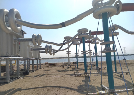
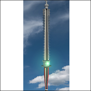
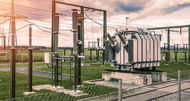
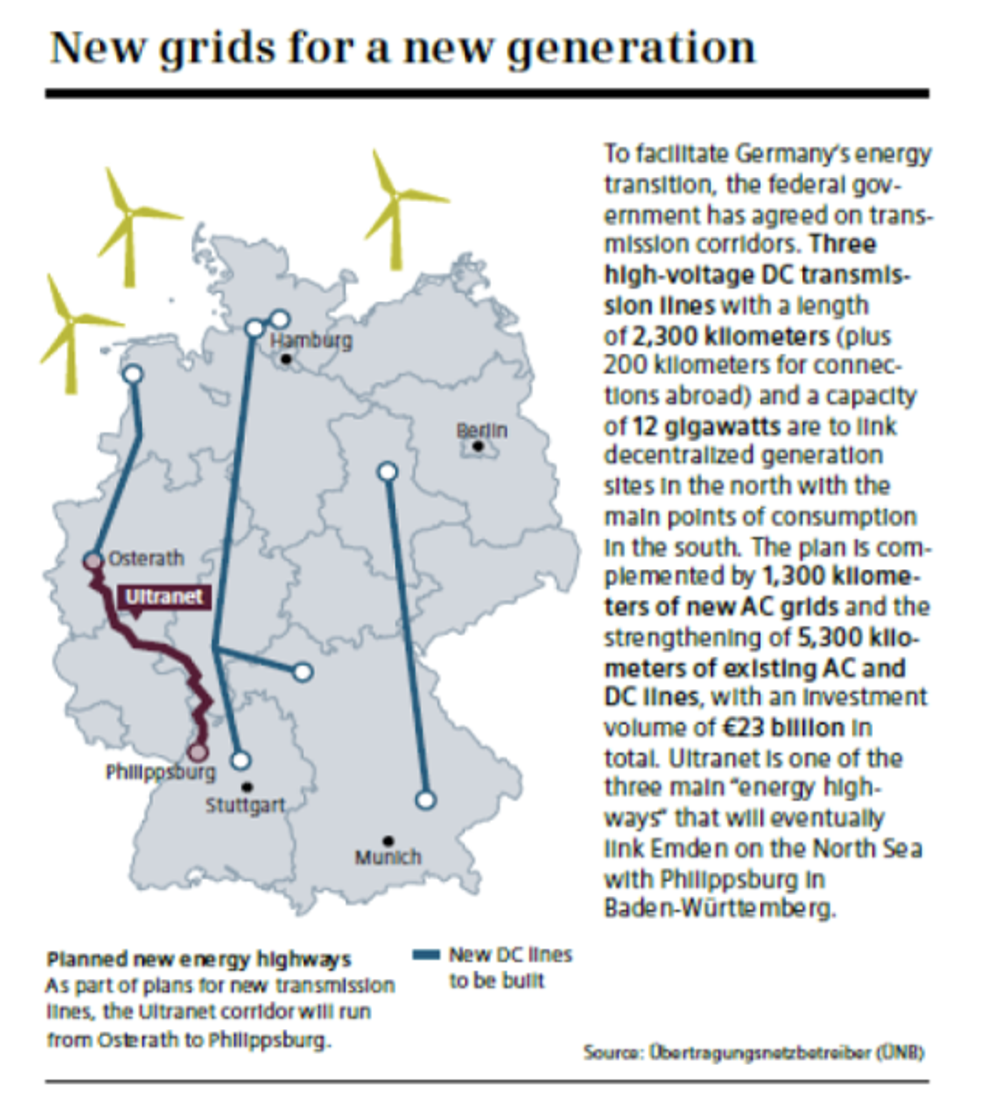
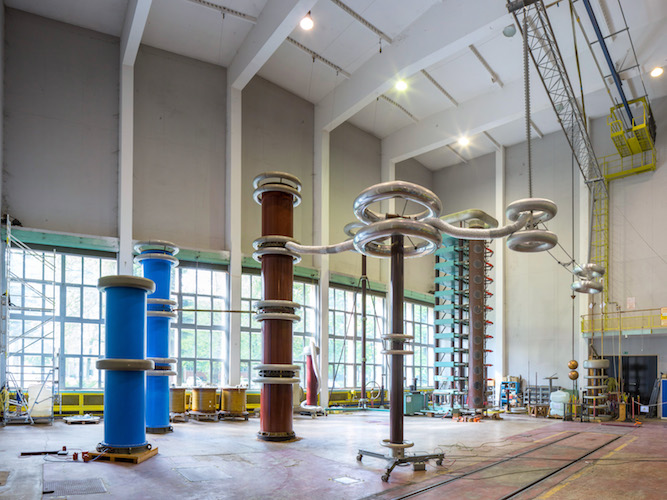
During a September 2014 symposium preceding the opening of a new HVDC test laboratory in Mannheim (see Fig. 2), different major TSOs emphasized the lack of multi-year experience with HVDC technology. Terna in Italy, for example, pointed out existing shortcomings and played a key role in developing reliable XLPE extruded cable based on Polarity Reversal Tests performed at CESI-FGH laboratories up to 350 kV. Indeed, in order to have higher thermal and electrical performance (e.g. operating temperature and more power deliverable), TSOs have been looking for new classes of extruded cables. In particular, German Transmission System Operators (GTSOs), in the frame of an Energiewende, have been looking for the first group of cable manufacturers able to supply at least 3000 km of 525 kV DC extruded cable systems (see Fig. 3).
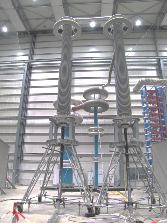

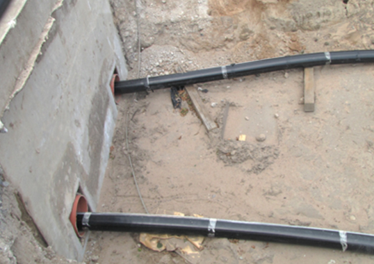
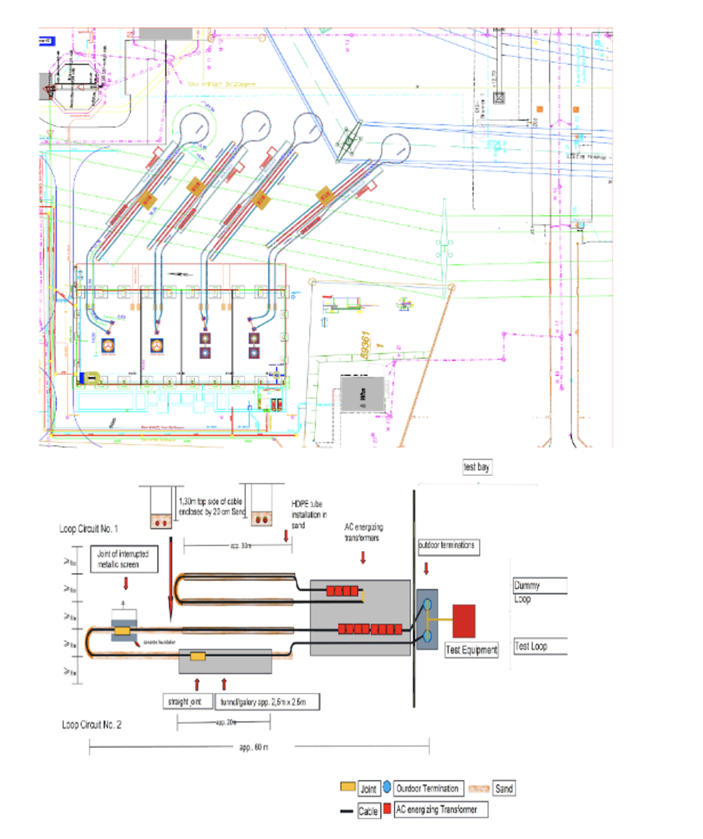
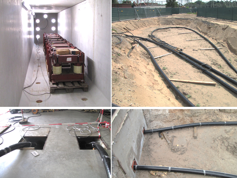
Following this stated need, they established an ad hoc qualification process (i.e. Type Tests and PQT) involving 4 cable loops tested in the new Mannheim facility (see Fig. 4). The PQTs began in August 2017 and the last test loop was successfully finished in January 2021. For the first time ever in the case of HVDC cable systems, the cable loops of a PQT were not tested on the floor of a laboratory (as per Cigrè TB 496) but mainly underground, representing real network situations such as urban tunnels, pipelines and joint bays, (see Fig. 4).
Four manufacturers were qualified after having successfully passed the required type tests, witnessed by independent parties. Moreover, 5 cable installations, each comprising over 100 m of cable, two joints and two outdoor composite terminations, underwent a PQT (one manufacturer participated with 2 different cable designs and insulation materials). The GTSOs prescribed a conductor cross-section under test as large as possible and not less than 2500 mm², although no indications were given for conductor material (all manufacturers delivered copper cables). Two different test institutes were selected to perform the PQTs.
With respect to life expectancy, the main focus of this qualification process was to obtain a clear understanding of cable system performance regarding thermal and electrical ageing before putting them into service in large transmission projects. One GTSO also requested having a replica of a real underground network layout, complete with cables and accessories, in order to be certain this could withstand the environmental stresses of each installation, e.g. cold temperatures, viaducts, crossings (see Fig. 5).
The specific test procedure, similar to that used for PQTs in AC, was applied for the first time ever in a real test on the highest voltage class of extruded cables system (525 kV DC). This greatly increased the level of complexity of long-term testing since, in an AC PQT each heating cycle is equal every other cycle and must be replicated 180 times. As such, in case of unforeseeable interruptions such as blackout or test circuit maintenance, any lost cycles had to be added at the end of the test before final verification procedures.
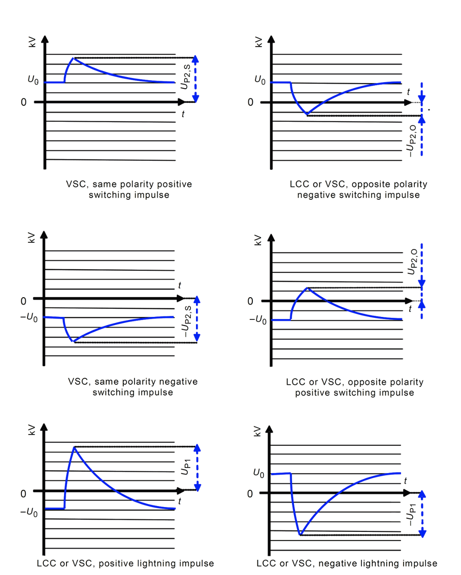
Conversely, in the case of the Long Duration Tests in DC, the distinctions between cycles performed at different polarities and load applications prevent using the latter procedure and make the test more difficult to manage. Table 1 shows the sequence of tests for LCC and VSC.
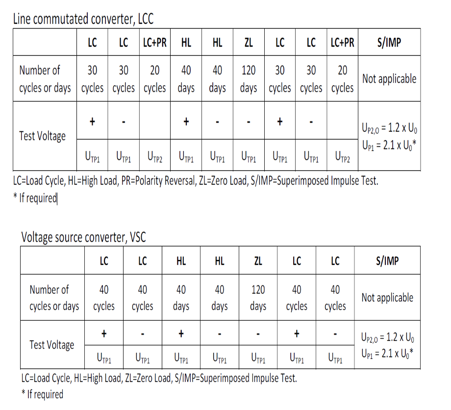
At the end of the heating cycle, superimposed impulse testing shall be carried out on the cable system with scope of acceptance for PQT.
This complex procedure aims to assess cable system integrity by simultaneous application of DC and impulses at different polarity, resulting in greater measurement complexity compared to a normal AC PQT (see Fig. 6).
Latest Requests from the Market
These days, bi-directional interconnection systems are being asked for due to integration and management of intermittent renewable sources as well as security of supply of electricity markets. This is the reason why utilities these days are requesting a polarity reversal endurance test, i.e. conducting further thermal cycles such as with the methods prescribed in Electra 189 except that applied DC voltage will be 1.4 U0 = 700 kV and polarity reversals will be carried out every 1 or 2 h up to a total of 3000 polarity reversals.
Moreover, network operators and utilities have recently highlighted occurrence of long transient overvoltages (LTOV), which can occur during operation of cable in point-to-point connections comprising VSC converter technologies, as preferred for extruded cables. For example, KEMA Labs was contacted to evaluate possible test circuits to simulate this phenomenon. This was verified, firstly by numerical simulation and subsequently by a pre-test where waveforms similar to those occurring in service were generated in the laboratory.
Laboratory Simulation of Transient Overvoltage Stresses Caused by Faults in HVDC Cable Systems
HVDC cables with polymeric insulation are tested according to IEC 62895. The tests are described as routine tests, sample tests, type tests and pre-qualification tests and requirements are described in the standards. However, TSOs and cable manufacturers have been contacting test laboratories such as KEMA Labs to carry out tests with waveshapes that exceed standard test requirements. These new requirements are based on results of numerical simulations of HVDC grids given that lengths of extruded HVDC cables are greatly increasing. In Germany, for example, projects such as SuedLink and SuedOstLink have been initiated to transport electrical energy over long distances from offshore wind parks in the North to the industrial areas in the South.
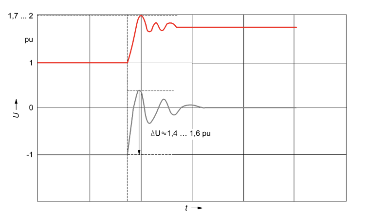
Simulations revealed that there can be a transient overvoltage stress to the cable such that, in the event of an earth fault in one polarity, the voltage in the other can rise to a value of 1.7 to 2 p.u. and exceed normal voltage for 200 ms or longer. Fig. 7 shows an example of such a voltage in the red curve. The faulted pole is meanwhile discharged with an oscillating waveform, as shown by the grey curve. In general, a cable system is subjected to a damped discharge in the faulty pole and a slow superimposed impulse in the healthy pole. Therefore, the request made to the laboratory was to generate waveforms as close as possible to the simulated curves to introduce this stress as an additional evaluation test for the future.
Requirements
During the past 2 years, several requests for testing such special waveforms, often called transient overvoltage (TOV), have been made and all contained two general waveshapes:
• Oscillating discharge (as per the grey curve in Fig. 7);
• Superimposed transient overvoltage in same or opposite polarity (as per the red curve in Fig. 7).
Zero-Crossing Oscillatory Discharge
This test can be described as an oscillating discharge of a pre-charged capacitor. Such damped oscillation can be described by several parameters, the main of which include:
• Pre-charging DC voltage, equal to U0 of the cable;
• Oscillating frequency;
• First and second peak of discharge, as parameter for the damping;
• Number of oscillations, as parameter for the damping;
• Time to reach 5% of U0, as parameter for the damping.
In most cases a test with 2 different frequencies is requested – a higher and a lower frequency. Table 2 shows typical test parameters.
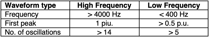
Since there is no loss-free circuit, the high-frequency test would require a pre-charge exceeding 1 p.u., when the first peak is expected to reach 1.0 p.u.

Superimposed Transient Overvoltage
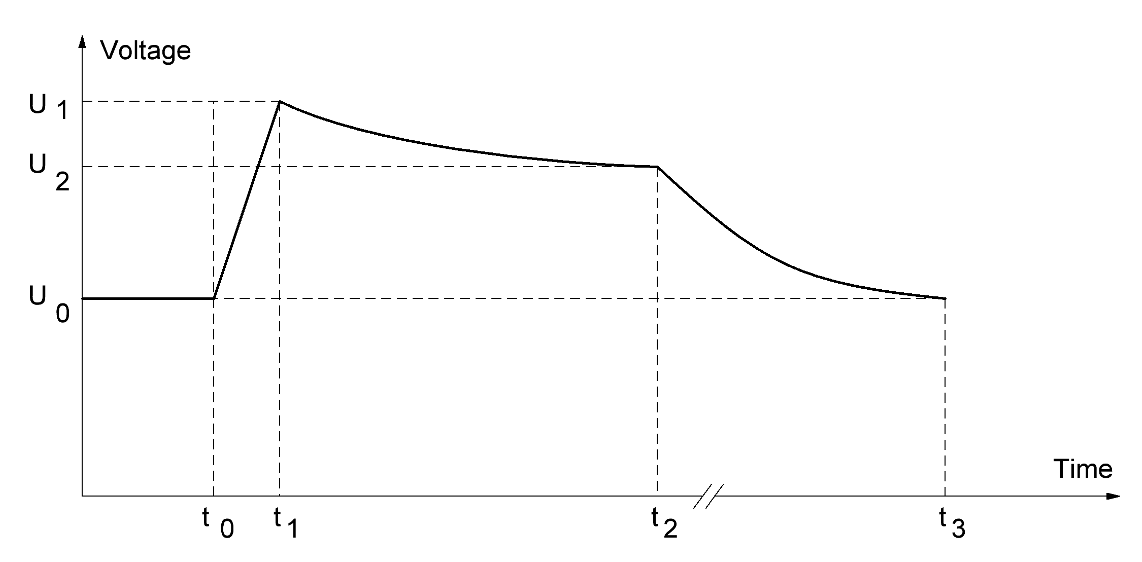
In a first attempt, this test can be regarded as a very slow impulse voltage superimposed to the pre-charged DC voltage. Therefore, similarities might be found to a superimposed switching impulse voltage test, as described in IEC 62895 and CIGRE Technical Brochure 496, “Recommendations for testing DC Extruded Cable Systems for Power Transmission at a Rated Voltage up to 500 kV”. Table 3 shows some of the parameters certain customers expect for the test voltage (see Fig. 8 as well).
Fig. 8 makes it clear that a real curve is not being shown since the voltage peak is too sharp and the time axis is not linearly scaled. Moreover, it might also be necessary to revise U1 and U2 for reverse polarity application since, according to CIGRE TB 496, the voltage will decrease by 1.4 … 1.6 p.u. This will result in an opposite polarity voltage U1 of -0,4 … -0.6 p.u.
Considerations for Generation of Test Voltage
The priority during evaluation of an upgrade in laboratory test capabilities (such as in the case of the Mannheim facility) has been to use as much existing equipment as possible. At the same time, it was assumed that tests would be carried out on a typical Type Test loop that, in the case of XLPE cable, has a capacitance of approximately 15 nF. The reason to choose a Type Test length is that TOV Tests are seen as special requests concerning design of a cable system and therefore should be done in conjunction with Type Tests.
The evaluation started with a numerical simulation to obtain a rough approximation of the magnitude of circuit components. After this simulation, a down-scaled laboratory test was carried out to verify results and to evaluate feasibility of the tests.
Zero-Crossing Oscillatory Discharge
Fig. 9 shows the general test circuit proposed. To simulate a failure in the laboratory, cable capacitance, CC, needs to be discharged by an inductor, LD. As an option, damping can be adjusted using a series resistor, RD. The cable must be pre-charged by a DC source and then discharged. To adjust the lower frequency, an additional capacitor, CADD, may need to be installed. The protection resistor, RP, is used to avoid an over current trip-out of the DC generator during discharge of capacitance, CC. A circuit breaker is to be used instead of a spark gap to avoid interruption of the discharge by extinction of the spark gap at zero-crossing. The voltage across the test object is to be measured with a universal voltage divider to see both AC and DC components (see Fig. 9).
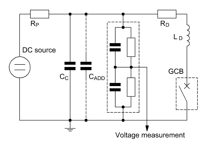
Numerical simulation confirmed that, with available equipment, all parameters requested according to Table 2 could be realized. Therefore, the circuit was built-up in the laboratory and a test was carried out with downscaled DC voltage. The voltage recorded for the discharge tests revealed a low damping caused by the air core reactors being used. In summary, all requirements would be fulfilled if cable behavior does not deviate from a circuit with lumped elements.
Superimposed Transient Overvoltage
If required test voltage is evaluated, it becomes clear that the parameters can be fulfilled by a double-exponential function voltage as delivered by an impulse generator and which is superimposed to the pre-charged DC voltage of the load. In reality, for a long time-to-peak, the damping resistor will lead to greatly reduced efficiency of the circuit. In addition, the limit of the time to half-value is defined by the charging resistors, which bypass the discharge resistors. Given this, test laboratories can have trouble reaching required voltage peak and time parameters at the same time.
An option to resolve this can be a rectifier that has predictable and reproducible behaviour. Indeed, it seems clear that a standard impulse generator can be used without major additional effort and only an additional external damping resistor, RD, may be needed. Fig. 10 shows the general test circuit.
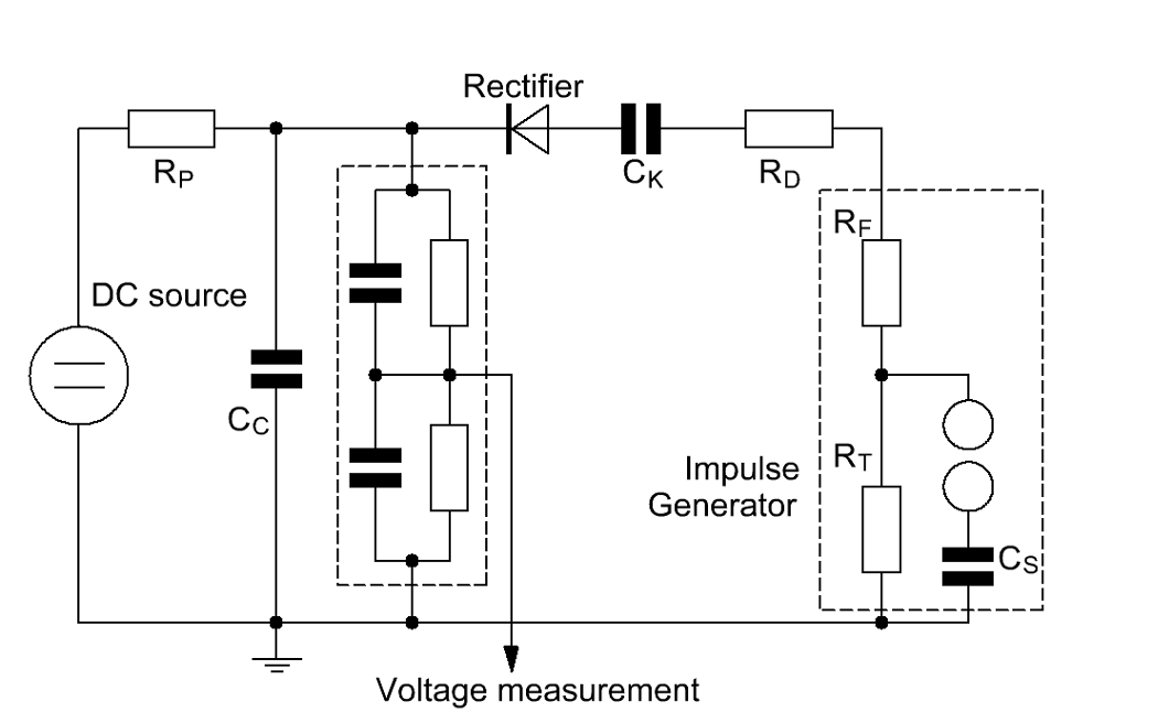
Cable capacitance, CC, is pre-charged to U0 by the DC generator. The impulse from the impulse generator is coupled by a capacitor, CK, as described in IEC 60230 but the cable will be charged or discharged by the impulse only so long as the current flows in the right direction through the rectifier. As soon as the output voltage of the impulse generator becomes smaller than the voltage of the cable, the current would change direction. This means that the impedance of the rectifier changes to a value determined by the internal voltage grading resistors, a value exceeding 500 MOhm. Therefore, the discharge time constant increases dramatically and will be determined mainly by the branch resistors of the voltage divider and the protection resistor, RP. Time to peak depends mainly on the capacitors, CS, CK and CC, and the resistors, RF and RD, and can be adjusted over a wide range.
To verify this assumption, laboratory tests were conducted with reduced voltage to show the impact of the rectifier. While the change in time to peak was not so large, the change in time to half-value was impressive. Since charges can no longer flow back easily to the impulse generator, this time is increased by a factor of about 50.
Additional laboratory tests with changing circuit parameters revealed that time to peak can be changed in the range of up to 10 ms while the time to half-value can be increased by up to more than 3 seconds. This latter case also requires an increase for the protection resistor, RP, or else the cable would be discharged by the DC generator (see Fig. 10). Finally, the limiting factor for the discharge is the resistive branch of the voltage divider. The divider used for the test has a total resistance of approximately 800 MOhm. If increased, it would become too influenced by stray capacitances.
Special care must be taken to the non-linear behaviour of the rectifier. Some conclusions from these downscaled laboratory tests included:
• the “classic” set-up for superimposed impulse tests shows a constant behaviour regarding the time to peak, independent from the DC pre-charge;
• if a rectifier is inserted, time to peak depends on the DC pre-charge;
• effect of the pre-charge is amplified if an external damping resistor is installed;
• for long times to-peak, an external damping resistor, RD, is essential but reduces efficiency;
• increasing charging voltages for the impulse generator reduce impact of the external damping resistor on time to peak.
If a rectifier is selected for the purposes of this test, certain parameters need to be specified to avoid damage to this device. One of these is maximum reverse voltage of the rectifier and another is maximum forward peak current. Also, maximum energy consumption must be taken into regard to avoid thermal runaway. Proper values can be found using numerical simulations.

Transient Overvoltage Stresses Performed on Real 525 kV Cable System
After the above computational simulations and downscaled pre-tests, the first official Transient Overvoltage Test (TOV) was performed for a real cable system loop consisting of 2 outdoor terminations, 2 joints and the DC cable. In fact, these tests, completed in April 2022, can open an important opportunity for TSOs and electricity supply utilities that need to protect themselves from special situations that can occur on their networks due to TOVs. For example, KEMA Labs has been asked to meet all the following requirements:
Oscillating Discharge Test (High-Frequency)
• Pre-charge with Uo;
• Discharge frequency between 5700 Hz and 8000 Hz;
• Number of oscillations >14.
Oscillating Discharge Test (Low-Frequency)
• Pre-charge with Uo;
• Discharge frequency below 400 Hz;
• Number of oscillations > 5.
Very Slow Front Impulse Test (Same Polarity)
• Pre-charge with Uo;
• Peak voltage 1.6 x Uo;
• Time-to-peak between 7 ms and 10 ms;
• Plateau time from 1.6 Uo to 1.5 Uo between 100 ms and 200 ms.
Fast Front Impulse Test (Opposite Polarity)
• Pre-charge with Uo;
• Peak voltage -0.6 x Uo;
• Time-to-peak 60 µs +/- 20%;
• Plateau time between 100 ms and 200 ms.
The cable system tested had a length that resulted in total capacitance of approximately 10.4 nF. Based on this, the test circuit was prepared in accordance with Fig. 9 and the oscillating discharge test was carried out first.
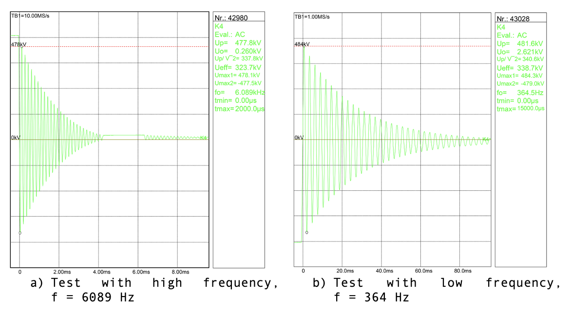
All requested test parameters were fulfilled. To attain this goal, a 65 mH inductor was used for the high frequency and a 1000 mH inductor for the low frequency. An additional capacitor was connected in parallel to the test object to reach the low frequency. This capacitor was realized by a series circuit of an appropriate number of capacitors of the impulse generator. In such case, care must be taken that these capacitors are stressed with a high DC voltage during the pre-charge phase. Since air-core reactors were used, the damping was very low. Therefore, damping was adjusted with a damping resistor of some Ohms to reduce number of oscillations.
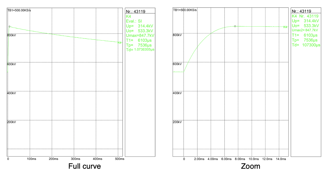
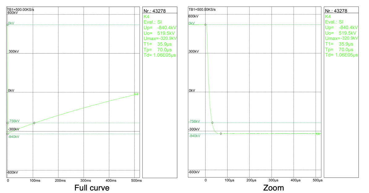
After this, the test circuit was prepared for the impulse tests. Since these would be full-scale, special attention had to be devoted to ensuring proper insulation distances within the laboratory. During these tests, it was found that the coupling capacitor was not needed for the same polarity tests since in this case the rectifier provided sufficient insulation. Therefore, the total efficiency of the circuit could be improved somewhat, depending on the value of the coupling capacitor. For the opposite polarity, either the coupling capacitor or a spark gap needed to be inserted to get the cable pre-charged. As shown in Figs. 12 and 13, requested parameters were reached for both, i.e. same polarity and opposite polarity tests. It should be noted that during the same polarity test, the high value for time-to-peak required an external damping resistor, RD, which dramatically reduces efficiency of the circuit (see Fig. 10).

Summary & Conclusions
In a changing electrical marketplace driven increasingly by renewable energy sources, the goal is to transport wind or solar energy to key demand centres, often over thousands of kilometres. Interconnectors using HVAC cables are currently limited to approx. 100 km based on established technologies and therefore HVDC solutions are preferred not only for submarine cables but also for long distance land applications.
To obtain higher thermal and electrical performance, TSOs have been seeking a new class of extruded cable. For example, German TSOs have begun looking for cable manufacturers able of supply extruded cable systems at 525 kV DC. Moreover, these TSOs have requested testing not be done on the floor of a laboratory but rather in replicas of real underground network layouts and with 525 kV DC cables and accessories able to withstand the specific environmental peculiarities of each type of installation. This has greatly increased the complexity of long-term tests, both in terms of test modalities and their management.
Experience gained during execution of PQTs has provided positive feedback on cable system behaviour, thereby increasing expected reliability of future connections in HVDC.
It is evident that successful passing of the GTSO PQT has boosted confidence among manufacturers of extruded cables systems with different types of cable and accessories to become qualified for 525 kV DC transmission projects – not only to supply German TSOs but also users across the globe. Indeed, it can be predicted that the GTSO qualification procedures will become a milestone for the HVDC cable market just as the BEWAG project was for HVAC extruded cable systems in early 1990s.
Recently, there have been increased requirements coming either from equipment manufacturers or from grid operators aiming to address such issues as: verifying the possibility of reversing flow of energy circulation in the event of changed needs in adjacent markets; withstanding electrical transients so as to give greater confidence for all transient phenomena that can occur in HVDC schemes (such as during pole-to-ground and pole-to-pole faults, faults on the AC side, etc.).
KEMA Labs Mannheim was requested to perform a feasibility study on the possibility of setting up test circuits that could enable laboratory testing of full-scale HVDC cable systems up to 525 kV according to the above-mentioned TOVs. The aim was to verify the ability of an HVDC cable system to withstand these types of non-standard stresses. After positive preliminary tests done at the request of one large manufacturer, tests were carried out on a 525 kV DC system immediately after a Type Test. In April 2022, an important goal was reached for this sector with the first Transient Over Voltage Test carried out on a 525 kV DC Cable System Loop consisting of the DC cable, two external terminations and two 2 joints.
REFERENCES
[1] IEA “Electricity Market Report 2020”.
[2] U. Vercellotti “HVDC links at increased voltage-CESI experience on extruded cable systems up to 525 kV”, AEIT HVDC Florence 9-10 May 2019.
[3] CIGRE Technical Brochure 496, “Recommendations for testing DC Extruded Cable Systems for Power Transmission at a Rated Voltage up to 500 kV” CIGRE WG B1.32, April 2012.
[4] R.D. Zhang “TenneT’s HVDC Cable Projects in Germany and Quality Assurance”, Jicable-HVDC17 – Dunkirk, France.
[5] IEC 62067 “Power cables with extruded insulation and their accessories for rated voltages above 150 kV (Um = 170 kV) up to 500 kV (Um = 550 kV) – Test methods and requirements”.
[6] IEC 62895 “HVDC power transmission – Cables with extruded insulation & their accessories for rated voltages up to 320 kV for land applications – Test methods & requirements”, May 2017.
[7] R. Nicolini, U. Vercellotti “Testing experiences on extruded cable systems up to 525 kV DC – challenges for the lab and need for further standardization”, CIGRE 3rd SEERC Conference.
[8] A. D. Shakib, H. Hartel, A. Krontiris, A. Menze, T. Rendel, J. Reisbeck, S. Beckler, 2020, „HVDC Cable Connections in a symmetrical monopolar configuration – Influence of single pole faults to the transient voltage behavior”, ew Magazin für die Energiewirtschaft, pp. 26-30.
[9] H. Jahn “Transient overvoltage stresses caused by faults in HVDC cable systems and their simulation in the laboratory”, JICABLE HVDC’21, Liège, November 2021.
[10] K. Helling, Cg. Henningsen, K. Polster, O. Bosotti, W. Mosca, M. Tellarini – JICABLE’95 – Versailles, France 25-29 June 1995 “Prequalification test of 400kV XLPE cable systems”.
[11] C. Freye, J. Kortenbrede, L. Vogelsang, F. Jenau, 2019, „Synthetic Laboratory Imitation of Transient Voltage Stresses of MMC-HVDC Links“ IEEE 54th International Universities` Power Engineering Conference (UPEC), Proceedings, paper no. 84, Bucharest, Romania.
[12] S. J. Frobin, C. Freye, L. Vogelsang, D. Wienold, A. Cimino, F. Jenau, M. Gamlin, 2020, “Large Scale Synthetic Laboratory Imitation of Transient Voltage Stresses of MMC-HVDC Links: Design Aspects on “Very Slow Front Overvoltages””, Conference VDE Hochspannungstechnik, Proceedings, pp. 365-370.