This edited contribution to INMR by Prof. Amedeo Andreotti and Santolo Meo at the University of Naples Federico II in Italy offers a detailed analysis of lightning-induced overvoltages in distribution networks, with focus on the mitigation effects that can be achieved using shield wires.
The first part is devoted to analyzing their role in case of indirect lightning, since this condition is more severe compared to the direct lightning on this type of network. The second part is devoted to assessment, for a realistic line configuration equipped with surge arresters, of the improvement which can be obtained by installation of shield wire.


Lightning transients can cause significant disturbances in overhead distribution lines, leading to both temporary and permanent faults. Several mitigation strategies have been proposed to limit such effects, including: (i) increasing the critical flashover (CFO) of the line, (ii) installing surge arresters (SA), and (iii) implementing shield wires (SW).
The first part focuses specifically on the approach (iii), namely addressing the advantages that can be obtained in the use of SWs in overhead distribution lines when stressed by indirect lightning. Indeed, the role of the SWs in direct lightning events is well known and well addressed, whereas for the indirect lightning events, despite extensive investigations in the literature, the effectiveness of SWs remains controversial. Some studies report a substantial reduction in overvoltages when SW are used, while others observe negligible improvements. Moreover, even in the studies which agrees in the benefits which can be gained using SWs, conflicting conclusions often arise due to the specific parameters, such as the relative height of the SW compared to phase conductors. Recent efforts by the authors have clarified this ambiguity by identifying a key indicator which can be used to quantify the mitigation effect: the Shielding Factor (SF). The concept of SF is not new: this is defined as the ratio of the voltage induced on a phase conductor when the SW is present, to the voltage induced in the absence of SW. However, the literature has presented divergent conclusions regarding the significance of this ratio. While some studies suggest that lines equipped with SW exhibit low SF (i.e., effective mitigation), others report high SF values, indicating limited effectiveness. Additionally, no clear consensus exists on how line configuration parameters – such as SW height – affect the SF. For example, some researchers assert that variations in SW height significantly influence the mitigation effect, whereas others report minimal or no impact. In the traditional literature assessment, a further complication arises from the difficulty in assigning a precise SF value to any given line configuration: due to the stochastic nature of lightning events and the variety of influencing factors (e.g., distance between lightning channel and line, ground conductivity, grounding spacing), it was considered impossible in the past to predict the exact mitigation performance of a configuration a priori. This represented a strong limitation both in the assessment of the mitigation in existing lines and the design of new ones. For example, given a desired SF value (e.g. SF = 0.7), according to the consolidated literature there was no straightforward method to determine the required line geometry to achieve that value reliably.
In the second part, an assessment is devoted to a realistic line configuration equipped with SAs to show how the addition of a SW can significantly contribute to the mitigation of the overvoltages produced under both direct and indirect lightning events.

Role of Shield Wires in Mitigating Effects Due to Lighting
The effectiveness of SWs in mitigating both direct and indirect lightning effects has been extensively investigated by many researchers.
During direct lightning events, SWs protect the overhead power line by intercepting the lightning stroke and providing a low-impedance path to the ground. SWs are traditionally used in high-voltage transmission lines to protect them from direct lightning; while their use in distribution lines is strongly limited for this type of lightning due to the frequent inception of back flashover (BFO), caused by the high potential which usually takes place between the pole/tower structure and phase conductors. Insufficient CFO levels and poor grounding resistance can facilitate BFO. To effectively reduce the impact of direct strikes, the SW should be grounded at every pole, the line should guarantee an adequate CFO, and the grounding resistance should be kept low. This highlights the importance of proper design practices and grounding when implementing SWs in distribution networks for protection from direct lightning.
In indirect lightning events SWs play a different role: SWs can help lower the overvoltage levels caused by nearby lightning strokes. This mitigation is due to the electromagnetic coupling between the SW and phase conductors, which reduces induced voltages regardless of the SW physical position relative to the phases. Stronger coupling leads to greater voltage attenuation. Recent studies developed by the authors have proposed a revised theoretical framework for understanding the mitigation provided by SWs in overhead distribution lines. This new approach introduces two fundamental insights that aim to clarify longstanding ambiguities and inconsistencies in literature.
A. Aspect 1: Parameter Classification
Historically, the various parameters influencing the effectiveness of SWs have been grouped indiscriminately, which has contributed to conflicting conclusions in earlier assessments. The revised approach argues that it is essential to distinguish between two categories of parameters:
Internal parameters: These refer to characteristics of the line that are within the control of the line designer. They include the absolute height of the SW, its height relative to the phase conductors, grounding resistance, and grounding spacing.
External parameters: These are uncontrollable variables that are not related to the line design. They include the front time of the lightning current, the distance between the line and the lightning channel, offset of the lightning strike relative to the grounding point, and the ground conductivity.
Table I summarizes the classification of parameters as internal or external.
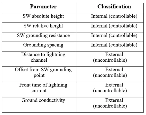
This clear distinction helps eliminate ambiguities and promotes a more structured understanding of the factors affecting lightning mitigation.
B. Aspect 2: Point of Mitigation Assessment
The second recent innovation concerns location along the line at which mitigation effectiveness should be evaluated. While existing approaches commonly assess the mitigation effect at the point of closest proximity between the line and the lightning channel, recent findings demonstrate that a more accurate evaluation should be conducted at the SW grounding point.
By jointly applying this revised parameter classification and refocusing the assessment point, it becomes possible to define the SF in a unique and controlled way. This represents a major shift in understanding, as it implies that the mitigation effect produced by the SWs can be precisely quantified and controlled since the parameter which quantifies it – the SF – assumes a unique and predictable value.

Methodology & Implications
The main implication of these recent insights is that the SF can now be treated as a line design specification in indirect lightning assessment. Designers can target specific SF values through the adjustment of internal parameters, which are all controllable: this forms the foundation for a more deterministic and rigorous approach to SW implementation in lightning protection strategies. The following briefly retraces the revised theoretical approach showing the essential steps needed to evaluate the role of SW in mitigating lightning-induced overvoltages in indirect lightning events. To enable a clear understanding of each influencing factor, the methodology begins with a simplified but insightful configuration: all conductors, including the SW, are assumed to be lossless and infinitely long; the ground is considered perfectly conducting, and the SW is grounded at only one point. Although such an idealized setup may not reflect real-world scenarios, it provides a valuable basis for analytical exploration. This allows development of generalized insights and facilitates the identification of key parameters affecting mitigation effectiveness. In this configuration, the mitigation effect, quantified by the SF at the grounding point, is expressed as:

where: v’a (t) and vb (t) are the voltages induced on the phase conductor and the SW, respectively; va (t) is the voltage that would be induced on the phase conductor in the absence of the SW; Zbb is the self-surge impedance of the line; Zba is the mutual surge impedance between the SW and the phase conductor; Rb is the grounding resistance. The impedance terms Zbb and Zba depend on the conductor heights and spacing, and are given by:

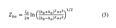
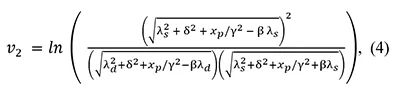
where: ζ0 = 377 Ω is the impedance of free space; hb and ha are the heights above ground of the SW and phase conductor, respectively; rb is the radius of the SW; s is their horizontal separation. As can be seen, the SF is influenced by both controllable line design parameters and external (uncontrollable) variables (see Table I). To deepen understanding, the methodology also examines the step-function case for lightning current, allowing the derivation of an analytical expression for the induced voltage vk (t,hk ) at height hk on the k-th conductor:
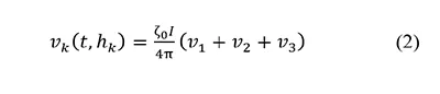
where the sub-components are defined as:
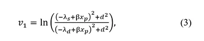

Auxiliary definitions used include:
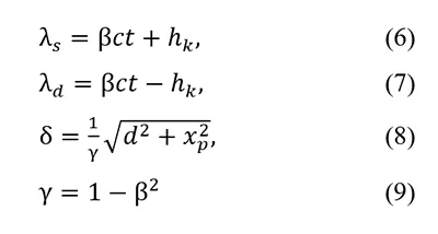
where: I is the step magnitude of the lightning current; β is the ratio of the stroke propagation speed to the speed of light c. This formulation provides a solid analytical framework for assessing the influence of key parameters and serves as the basis for subsequent evaluations and comparisons. It has been demonstrated that the exact solution of the induced voltage at the considered conductor location can be effectively approximated by a first-order expression: this simplified expression corresponds to the Rusck approximation, which is given by:
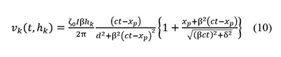
Leveraging this approximation, the induced voltage at the grounding point becomes directly proportional to the height of the conductor being considered: this leads to a new form of the SF, now expressed in terms of the conductor height:

Under this condition, which is completely justified both on a theoretical and a practical basis, the SF becomes dependent exclusively on internal parameters: the conductor arrangement (e.g., Zba, Zbb), the respective conductor heights (ha, hb), and the grounding resistance Rb. As consequence, the influence of external parameters becomes negligible, and the protection effectiveness can be accurately quantified.

Evaluation of Protection Schemes With & Without Shield Wire
This section investigates the lightning performance of a distribution network equipped with different protection schemes, with particular focus on the role of a SW when added to a line equipped with surge arresters. The effectiveness of these configurations is influenced by several key parameters, the spacing between surge arresters (DSA), the insulation strength of the line, quantified via the CFO, and, of course, the presence or absence of the SW.
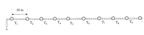
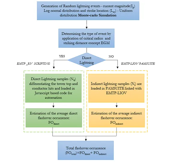
The analysis is carried out on a test distribution line composed of ten towers. Each tower is 10 m tall and supports a three-phase conductor arrangement. The SW, when present, is installed 0.8 m above the topmost conductor ad with the approach presented in the previous section is assessed to be SF=0.65. The network configuration used for this assessment is illustrated in Fig. 1. The performance is evaluated under both direct and indirect lightning strokes, following the simulation procedure using the code EMTP detailed in Fig. 2. For direct strokes, a first-stroke lightning current is modeled as per the Heidler waveform, with parameters listed in Table II.

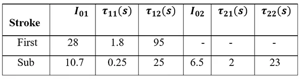

where η is a peak correction factor ensuring that the waveform peaks at the correct time and magnitude, Ipeak is the peak current, τ1 and τ2 are time constants that shape the rise and the decay of the waveform, respectively, and n is a dimensionless shape factor that adjusts the sharpness of the waveform’s rise.
Each stroke is injected at the top of each of the ten towers, ranging from (T1 ) to (T10 ). For every simulated event, the occurrence of flashover is recorded, and the protection rate is computed accordingly: the protection rate is defined as the ratio of lightning events that do not cause flashovers to the total number of events, serving as a quantitative measure of the protection scheme’s effectiveness. The tower and pole impedances are calculated according to their height and base radius; the surge impedance (Zt) of the tower results to be 300 Ω; the surge impedance (ZP) of the pole results to be 210 Ω. The grounding resistance of both towers and poles is 25 Ω. In the present modeling framework, this constant Rg does not strictly represent DC grounding resistance but is rather treated as an effective equivalent resistance under transient conditions that lies within the typical range (between 18.2 Ω and 45.5 Ω, based on local soil conditions and grounding geometries provided by the industry) as reported for poles in distribution networks. A soil resistivity value of ρ= 33 Ωm was selected based on the average ground conductivity data provided for the test site region.
In the case of indirect strokes, using the same waveform for the lightning current, the lightning channel is located 50 m in front of and between each pair of towers along the span from (T1 ) to (T10 ). This setup allows for assessment of the line’s vulnerability under realistic exposure to nearby strokes. Results are presented as average protection rates for each CFO level, allowing an evaluation of how insulation strength correlates with overall lightning performance under different protective configurations.
In the simulations of Fig. 3 no SW is installed, and the influence of SA placement intervals on protection performance under direct lightning events is shown; the results indicate that decreasing the SA spacing significantly enhances the protection rate, with shorter intervals (e.g., 50 m) achieving over 90 % flashover prevention at higher CFO values. In contrast, larger intervals (e.g., 200 m) exhibit a significantly lower protection rate, demonstrating the importance of optimized arrester placement in mitigating lightning failures.
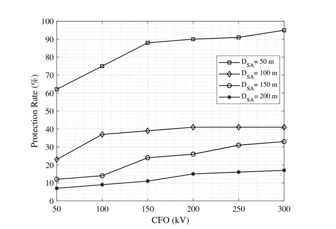
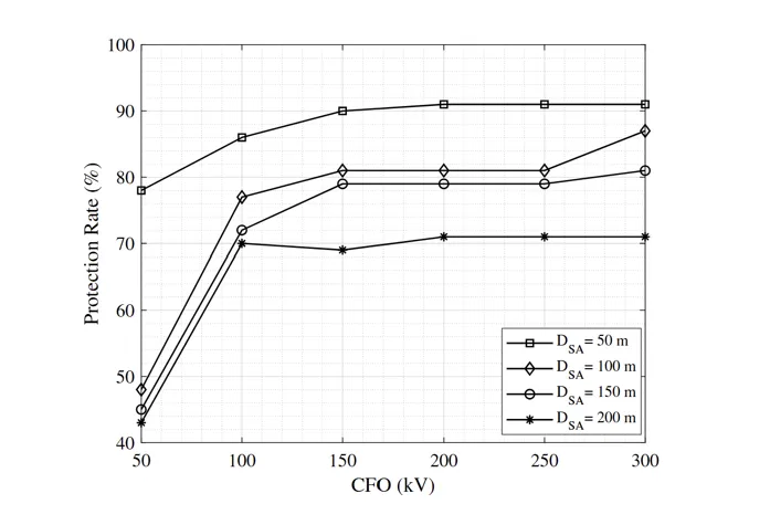

Fig. 4 illustrates the results for the same line configuration of Fig. 3, but this time under indirect lightning events. In this case, the lightning stroke is located 50 m in front and between each tower, spanning from T1 to T10 of Fig. 1. The results indicate that closer SA spacing significantly enhances protection performance, particularly at lower CFO levels. For instance, at a CFO of 100 kV, the protection rate exceeds 80% for the 50 m spacing but remains lower for wider spacing intervals. As the CFO increases beyond 150 kV, the variation in protection among different spacing configurations reduces, indicating diminishing returns from closer arrester placement at higher insulation levels.
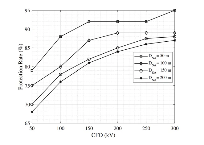
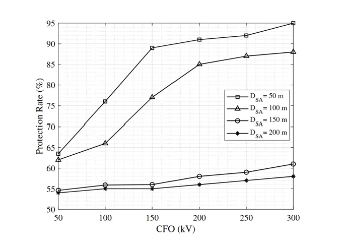
Similar analysis is repeated this time introducing the SW with a SF=0.65: Fig. 5 shows how the combined use of SW and SAs can lead to significantly improved results.
Fig. 6 demonstrates the performance of the same configuration of Fig. 5 under indirect lightning conditions. In this case too, the SW plays a significant role in improving the protection rate, and the effectiveness of SWs is particularly pronounced at higher CFO values.
The study has demonstrated that combining SAs with SWs results in a consistent performance improvement of approximately 20–30%, as an average, in flashover resistance under both direct and indirect lightning conditions compared to using SAs alone.
This synergistic approach enhances the overall effectiveness of the lightning protection system. It is highlighted that strategic placement of SAs, when coordinated with appropriate SW coverage, offers a technically viable solution for improving lightning resilience in distribution networks.
Conclusions
The above discussion has been structured into two parts: in the first, it was explained how the role of the SW in overhead distribution lines in mitigating the overvoltages under indirect lightning events can be precisely assessed, in contrast with consolidated literature. This is a fundamental result, both on assessing the performance of existing lines, but especially in the design of new ones.
In the second part it has been shown that integrating SAs and SW offers superior performance, after exploring various protection combinations. An important aspect is strategic deployment of SAs, which involves optimizing their placement to achieve maximum protection with minimal investment, when combined with use of SW can be fruitful in improving line lightning performance.



References
[1] A. Piantini, and J. M. Janiszewski, “Lightning induced voltages on overhead lines: The effect of ground wires,” in Proc. 22nd International Conference on Lightning Protection (ICLP), Budapest, Hungary, Sep. 19-23, 1994, pp. R3b/1–R3b/5.
[2] P. Chowdhuri, and E. T. B. Gross, “Voltages induced on overhead multiconductor lines by lightning strokes,” Proc. IEE, vol. 116, no. 4, pp. 561-565, Apr. 1969.
[3] A. Andreotti, A. Pierno, V. A. Rakov, and L. Verolino, “Analytical formulations for lightning-induced voltage calculations,” IEEE Trans. Electromagnetic. Compat., vol. 55, no. 1, pp. 109-123, Feb. 2013.
[4] M. Brignone, D. Mestriner, R. Procopio, A. Piantini, and F. Rachidi, “Evaluation of the mitigation effect of the shield wires on lightning induced overvoltages in MV distribution systems using statistical analysis,” IEEE Trans. Electromagn. Compat., vol. 60, no. 5, pp. 1400-1408, Oct. 2018.
[5] A. Andreotti et al. “On the role of shield wires in mitigating lightning-induced overvoltages in overhead lines-Part I: A critical review and a new analysis,” IEEE Trans. on Power Del., vol. 38, n. 1, pp.335-344, Feb. 2023
[6] A. Andreotti et al. “On the role of shield wires in mitigating lightning-induced overvoltages in overhead lines-Part II: Simulation results for practical configurations.” IEEE Trans. on Power Del., vol. 38, n. 1, pp.345-352, Feb. 2023
[7] N. Ravichandran, A. Andreotti, A. Di Pasquale, M. Pagano, D. Proto, E. Stracqualursi, R. Araneo and L. D’Orazio, “Selection of viable distribution line surge arrester for prospective optimal protection, in 2023 AEIT International Annual Conference (AEIT), 2023, pp. 1-6
[8] N. Ravichandran, D. Proto, A. Andreotti, “Surge arrester optimal placement in distribution networks: A decision theory-based approach,” Electric Power Systems Research, vol. 234, p.110744, 2024
[9] N. Ravichandran, A. Andreotti, R. Araneo, J. Cao, J., L. D’Orazio, Y. Du, D. Proto, and E. Stracqualursi, “Improvement of the lightning performance of overhead distribution lines: Possible solutions,” in 2023 International Symposium on Lightning Protection (XVII SIPDA), 2023, pp.1-6
[10] N. Ravichandran, D. Proto, D., F. Mottola, and A. Andreotti, “Multi-Objective Optimization for Lightning Protection in Distribution Networks: A Novel Approach Based on Design of Experiments,” IEEE Access, vol. 13, pp. 45215-45226, 2025
[11] CIGRÉ, “Guidelines for representation of network elements when calculating transients,” CIGRÉ Technical Brochure 39, Tech. Rep., 1990.
[12] IEC 60071-2:2018 – Insulation Co-ordination – Part 2: Application Guidelines. Geneva, Switzerland: International Electrotechnical Commission (IEC), 2018.
[13] E-Distribuzione, “Internal report, Codice Contratto JA10112065,” E-distribuzione, Tech. Rep., 2021, internal document.
[14] O. ITU-R, “World atlas of ground conductivities,” 1999.