The most important criterion for the decision between an overhead line and a cable remains cost. Based on this, overhead lines will always be preferred. But the comparative cost disadvantage for cables is decreasing due to new materials and improved production processes. At the same time, decisions regarding new overhead lines are increasingly being affected by issues such as aesthetics, reliability and public acceptance. The aesthetic aspect is expected to become most important for MV systems, especially in big cities.
This edited past contribution to INMR by Professor Klaus-Dieter Haim at the University of Applied Sciences Zittau/Görlitz in Germany examined trends and developments in technologies for cables and accessories.

Due to much better reliability, the relative proportion of MV overhead lines compared to cables is expected to decrease, not only in major cities but also in rural networks. For example, as evident from Table 1, the typical outage rate of new XLPE cable is outstanding – far better than for older PE or paper insulated cable and also much better than for a typical medium voltage overhead line (see Table 1).
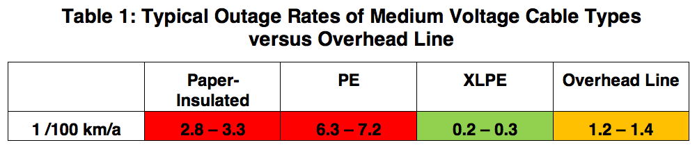
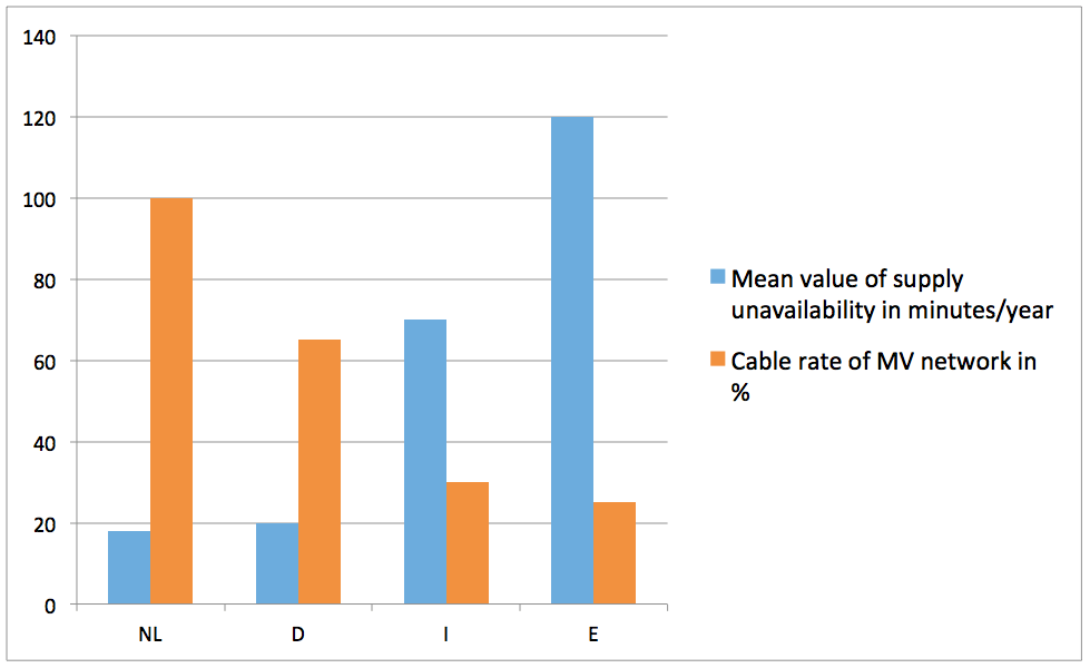
Fig. 1 compares mean value of unavailability along with cable rate in the Netherlands, Germany, Italy and Spain and it is quickly apparent that a higher cable rate in the MV network can greatly influence system reliability. Sweden, for example, has recently begun increasing its MV cable rate with the goal of reducing the impact of severe weather events such as heavy snow and high winds.
The situation at high and extra high voltage levels, however, is different. Because of higher cost factors, overhead lines will continue to dominate transmission system for a long time to come, perhaps forever. Nevertheless, in certain mega-cities different applications of high voltage cables up to 400 kV for some parts of the transmission system will be used and the number of such projects will increase significantly. Another possibility is utilization of gas insulated lines (GIL) that combine the advantages of an EHV cable and the transmission capacity of an EHV overhead line. But the investment cost factor here is much higher than for cable.
Cable Design
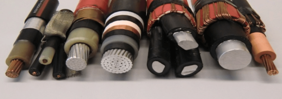
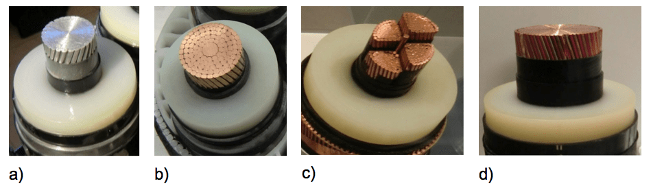
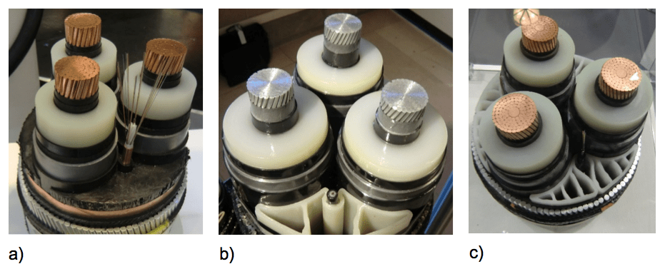
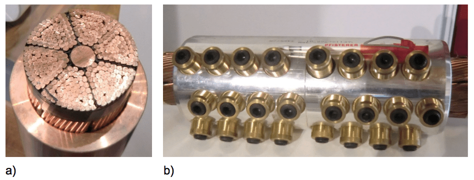
The design of medium voltage cables could now be considered as fully mature. Still, the high variety of different cable constructions used worldwide (estimated at nearly 100) will require efforts toward some standardized, maintenance-free and environmentally-friendly design. At the moment, conductors can be stranded copper or aluminum or solid aluminum while insulation material can be XLPE or EPR having a fully bonded or peelable outer semi-conducting layer. The cable screen can be a copper wire or tape screen as well as a laminated aluminum screen covered by a PVC or PE outer sheath. The MV system can consist of three single core cables or one three core cable. In the case of three core cable, steel wire armoring is common. Selection from among this broad assortment of different cable constructions depends mainly on historical factors as well as on local laying and economic conditions.
Insofar as HV and EHV AC cable design, this could now also be considered as fully developed. The conductor is stranded aluminum or copper and insulation material is XLPE – always with a fully bonded outer semi-conducting layer. The screen can be a lead sheath or welded aluminum sheath, a copper wire screen or a combination of copper wire screen and laminated aluminum sheath.
For subsea interconnections and to connect growing populations of off-shore wind parks, AC and DC submarine cables have become increasingly important and this applies to DC land cable as well. Three core submarine cables are used for AC applications and single core cables for DC.
The price and weight advantage of an aluminum conductor at medium voltages is an important benefit and therefore use of solid aluminum conductors will likely increase in the future. In some cases, this weight advantage applies as well for HV and certain submarine cable applications. By contrast, in the case of EHV cable systems, aluminum conductor needs much more insulation material to allow the same transmission capacity and copper is therefore preferred, particularly at the upper range of cross-sections. To reduce the skin effect in AC cables, individually insulated strands as a so-called ‘Milliken conductor’ or enameled wire conductors are possible and require special connectors.
The insulating material for future medium voltage cables will likely be XLPE, EPR and perhaps more and more polypropylene as a kind of ‘green’ cable insulation alternative. The limit for EPR insulation is the HV level because of its loss factor, which is much higher than for XLPE insulation. HV DC and EHV AC polymeric cables will only be XLPE type while some EHV DC submarine cables will still use special paper-impregnated insulation.
In order to reduce cost, the screen design of MV cables will probably go in the direction of laminated aluminum screens while, for HV cables, a combination of copper wire screen and laminated aluminum sheath is the most cost effective and installation-friendly solution. To reduce screen losses in single core cables, cross bonding of the screen is important. A wire screen therefore offers a convenient way to put the screen outside the joint, where the six screen terminations can easily be connected in a screen connection box. Applying cross bonding for other screen solutions requires an additional contact device and makes installation more complicated.
Application of high temperature superconductor cables for both medium and high voltage has moved from the prototype phase to the first field installations. For example, a 10 kV three core coaxial such cable with length of one kilometre and nominal current of 2.31 kA was installed in 2014 in the German city of Essen.

Connectors
Connection of cable conductors can be done by soldering, welding or by using a compression or shear-bolt connector. Heat from soldering or welding is a problem for XLPE cables and therefore use of compression or mechanical connectors is standard at all voltage levels. For LV and MV applications, the classic compression connector is now more and more being replaced by a shear bolt connector. The advantage of a mechanical connector becomes obvious if one considers the many different sizes, materials and shapes of cable conductors.
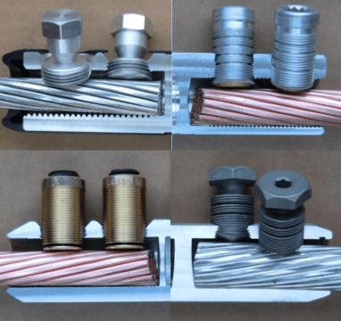
Even for HV and EHV with cross sections up to 2500 mm², more and more shear bolt connectors are now becoming available and connector technology will clearly move in this direction.
The connector is one of the most important components in a joint and can be the reason behind thermal destruction of joint insulation. That is why the connector should be designed to minimize risk of errors during installation. A mechanical connector fulfils this requirement better than a compression connector. Each type of connector must be able to carry the nominal current of the cable as well as the maximum short-circuit current of the network for a certain time, without overheating. This must be confirmed by long term as well as short circuit testing.

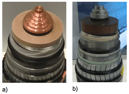
Joints
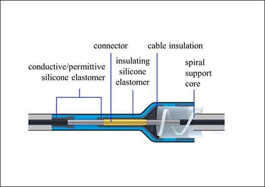
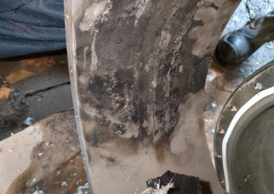
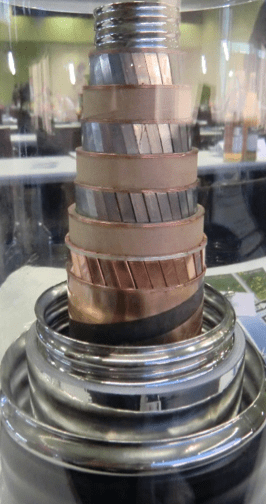
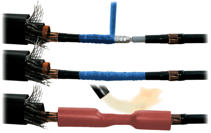
A straight joint is a connection of two identical single or three core cable ends consisting of connector, insulating body that includes stress control devices, screen connection and outer protection against moisture and mechanical damage. A transition joint is a connection of two different cables ends – most often to link paper and polymeric-insulated cables. At MV, heat shrink joints are used widely these days for straight and transition joint applications and this is likely to continue in the future. It is a cost-efficient and robust solution, suitable for all cable types and sizes. The main disadvantage is the number of components and installation steps. If application of heat is not possible or for any other reasons linked to the known disadvantages of heat shrink joints, use of slip-on or cold shrink joints is also common at MV levels. The usual material of the joint insulation body, which can be either a single piece or three piece solution, is silicone or EPDM.
In the case of HV and EHV cables, heat shrink joints are not applied and it is necessary to use a pre-fabricated, factory-tested silicone or EPDM insulating body instead. The trend here goes from slip-on to cold shrink technology for reasons linked to easier installation of cold shrink accessories.
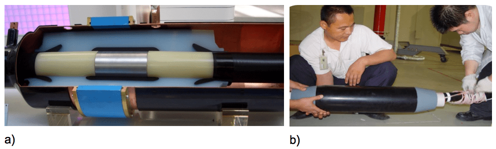
A one piece solution is more complicated in production and installation and requires a ‘parking position’ on the cable insulation, but can be fully pre-tested in the factory. Cold shrink technology combines the advantages of a single piece, pre-tested insulating body with an easy installation procedure. To achieve moisture and mechanical protection of joints, heat shrink components or cast resin filled shells are commonly used in combination with metallic radial water barriers.
For all joints and terminations it is indispensable to apply a stress control element at the end of the outer semi-conducting layer. In the case of polymeric insulated cables, two different design and material solutions are now widely accepted – each offering different advantages and application limits. The classical geometrical stress control system is suitable for all voltages while the refractive stress control is used mainly for medium voltages.

Terminations & Plug-In Connectors
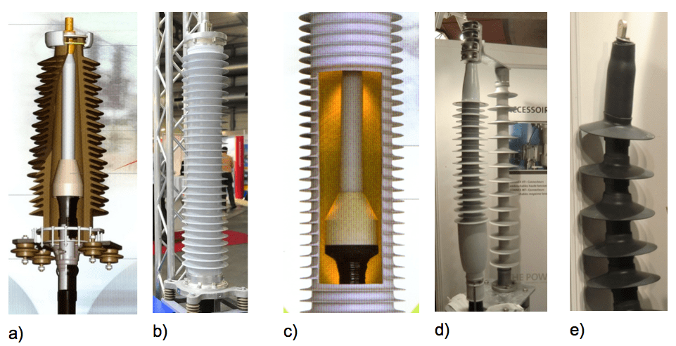
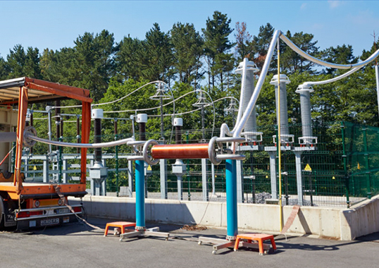
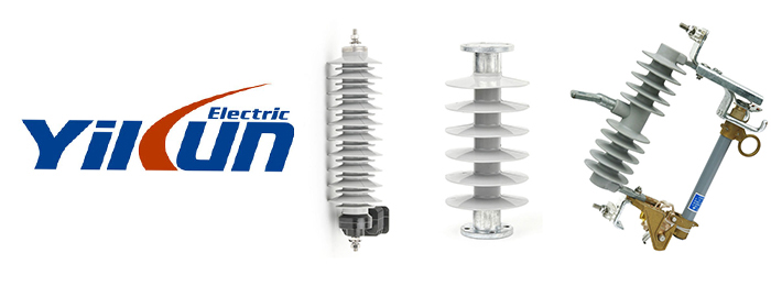
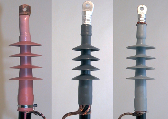
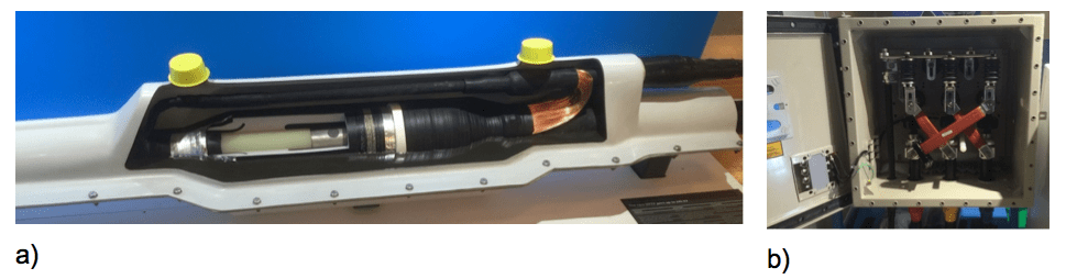
Terminations and plug in connectors are necessary to connect the cable end to an overhead line or to switchgear or transformers. All types of installation technologies are used in the case of medium voltage terminations, including heat shrink, slip-on and cold shrink. For HV XLPE cables, the classic outdoor termination is fluid-filled with a porcelain insulator housing. This type of termination has had long service experience with excellent resistance against tracking, radiation and pecking by birds. Nevertheless, in recent years composite housings have grown in popularity due to additional advantages such as excellent hydrophobicity, low weiight and resistance to earthquake or explosion. A relatively new design of termination for polymeric cables consists of a stress control element along with a composite insulator filled with either silicone gel or insulating gas.
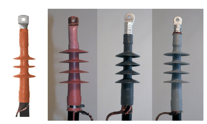
A new generation of terminations, coming from the medium voltage level are so-called dry type units. These offer such advantages as easy installation, seismic and explosion resistance and no need for oil filling.
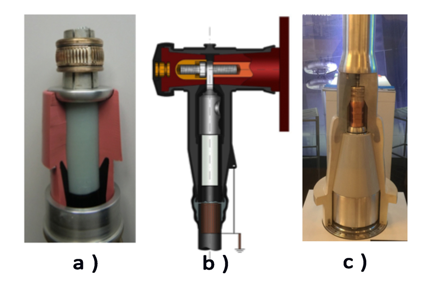
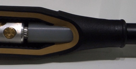
Especially at medium voltages, more and more cables are connected to SF6 insulated switchgear and plug-in connectors are used in these installations. There are two standardized such plug-in systems available on the market: the outer cone connector system is used widely in MV ring main units and the inner cone system is typically used in MV primary substations and also for HV applications. An inner cone system with bushing, including the contact system, is on the market for all HV levels up to 400 kV and can also be used for outdoor terminations and joints. It is expected to become one of the main components used in cable accessories at all voltage levels.