The architecture of power systems has recently been the subject of change as the common structure with centralized generation and one directional flow is gradually being replaced. The emerging power network concept sees both energy generators and consumers distributed. At the same time, continuously increasing environmental concerns as well as regulations have resulted in widespread installation of renewables. More storage devices are now also being incorporated into networks to cope with sudden increases in generated energy.
To facilitate energy flow from renewables to the power network, proper voltage level is maintained by means of transmission controllers. These consist of high frequency switching elements whose operation introduces high frequency harmonics that are propagated in the vicinity of installed controllers. On one hand, a high content of harmonics is another emerging issue for a power network. On the other, research has shown the potentially harmful effect of high frequency signals on reliability of electrical insulation. Despite the above, harmonic content has for many years not been considered, either during design or in the testing phase of electrical components.
This edited past contribution to INMR by experts at Royal Lovink Enertech and at Delft University of Technology in the Netherlands reviewed literature on influence of harmonics on reliability of cables, terminations and transformers. It also proposed an approach to model influence of high frequency on electric field and temperature distribution in two types of medium voltage cable terminations.


For decades, electrical systems have been providing continuous and unidirectional power flow – from centralized plants, through transmission and distribution networks, to the end consumer. Daily cycled demand for electrical energy was balanced by prognosis for generation. As part of this paradigm, components installed in T&D networks were stressed mainly by voltage level, transferred power and the environment in which they were operated.
In simple terms, such components consist of two major structures that are subject to stress during operation: the active part, which is responsible for conducting current; and the electrical insulation structure that is responsible for insulating areas having different potential.
Detailed investigation of power network components has found that more than 70% of failures relate to problems with the insulation system. In this regard, the life of electrical equipment is determined principally by the life of its insulating system. Factors that contribute to ageing of electrical insulation have been categorized into: electrical, thermal, mechanical and chemical. Over the past decades, stresses affecting electrical equipment and that are characteristic for certain types of networks and environments have required development of test procedures, as presented in various IEEE or IEC standards. The main goal of these tests (e.g. type tests) has been to verify the hypothesis that equipment of a certain design is able to operate for a period of typically 30+ years. However, as discussed, such test procedures have been developed based on experience and therefore do not cover new phenomena such as effect of harmonics caused by new network components or thermo-mechanical stresses due to high variations in load.
Network of the Future
Existing power networks face major changes with respect to types of energy sources and their deployment. In addition to conventional power plants, more and more renewables are being installed. Wind parks, for example, are more and more being connected to transmission lines while solar (photovoltaic) systems connect to low and medium voltage level distribution networks. In addition, energy storage systems are increasingly being incorporated into distribution networks to accumulate surges when supply exceeds demand.
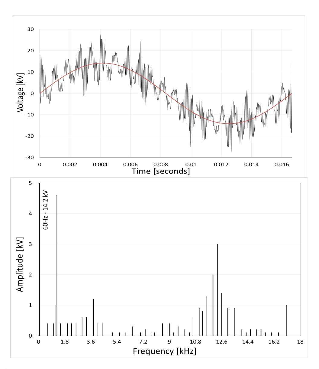
Changeability in weather conditions will therefore increasingly determine the amount of energy generated. To facilitate energy flow during peak-periods while maintaining the proper voltage level, use of high-frequency power converters is necessary. These are meant to switch the input DC voltage at high frequency to produce a wave shape as close as possible to AC at the output. This way, converters can be used as links between the DC and AC systems (renewables) or between AC and other AC systems of different frequency. However, the desired shape of the created wave is often far from purely sinusoidal. Depending on load and topology of a network, the distortion in the base harmonic can reach several per cent. Fig. 1 offers an example of a sine wave distorted by respective harmonics generated by the Eagle-Pass Converter Station connecting the U.S. and Mexican power grids.
Peril of Harmonics
The adverse effect of harmonics on reliability of power components was first noticed in 1950 in the supply system of London’s underground transport. Oil-impregnated paper insulated cables connected to mercury arc rectifiers were showing high failure rates and the harmonics being generated turned out to be the source of these recurring failures. Since then, as shown in some of the References, harmonics have been identified and proven responsible for deterioration and breakdown of insulation systems in liquid-filled transformers, capacitors and underground polymeric cables.
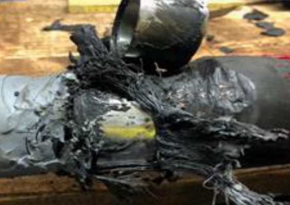
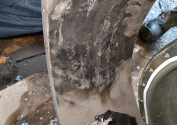
In Ref. #15, for example, the authors investigated the influence of high frequency voltage on a cable termination with non-geometric field control. Infrared scans of the components being investigated revealed increased temperature in the vicinity of the field control and it was concluded that hot spot temperature was proportional to applied frequency and voltage. Ref #6 presents details of high frequency tests performed on cable terminations with geometric and non-geometric (resistive/refractive) stress control arrangements. Here, terminations were run at the rated voltage where the frequency of the base harmonic was 60 Hz. On top of base frequency, a high frequency signal up to 10.6 kHz was superimposed. The test ran several hundreds of hours. While terminations with geometric field control did not show any abnormal behaviour, all terminations having refractive stress control failed. The authors pointed to two reasons for this result: first, for the non-geometric field control method, the field distribution around the edge of the semi-conductive layer was strongly related to frequency value; second, increased field resulted in higher losses generated. The latter brings a commonly known concept of the power dissipated in the insulation as caused by the dielectric losses (eq.1).
![]()
where:
P is dissipated power [W];
U is the voltage across the insulation [V];
C is the sample capacity [F];
tan δ is the dissipation factor characterizing given insulation.

Numerical Simulations
To gain a better understanding of this problem, it was decided to further investigate the influence of different frequencies on geometric and resistive field grading systems. Distribution of electric field was simulated using Comsol Multiphysics. A cable example was considered with dimensions as specified in Refs. #12 & 16.
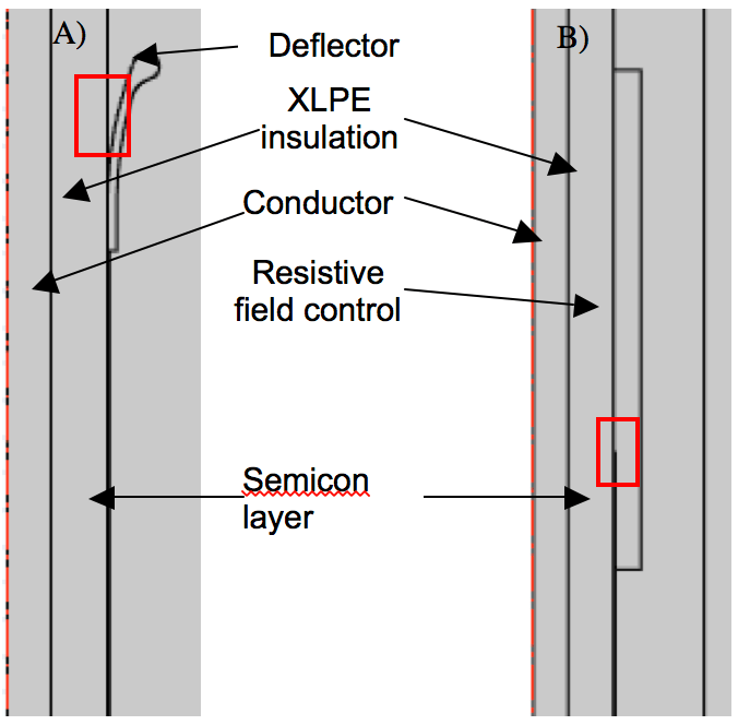
Fig. 2 shows the cross sections of the simplified arrangements. For the arrangement with geometric field control, the focus was on the area between the deflector and the cable’s XLPE insulation. In the case of resistive field control, the vicinity of the edge of the semi-con layer edge was investigated. (both spots are marked with red squares in the Fig. The choice can be justified by the fact that these are areas that experience relatively high values of electric field. Table 1 summarizes the values of electrical parameters characterizing the materials in the arrangement being simulated.
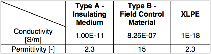
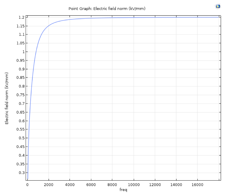
For the FEM simulations, voltage frequency varied between 50 Hz and 18 kHz, to best mimic the span of frequency presented in Fig. 1. Applied voltage was 19 kV to ground and ambient temperature was assumed as 293 K. The simulations revealed field behaviour in the areas under investigation. In the case of geometric field control, it was observed that the value of electric field is independent of frequency – in line with the conclusion from Ref #5. By contrast, for the case of resistive field control, value of electric field in the vicinity of the semi-conductive edge increased four-fold within the frequency span investigated, as depicted in Fig. 4.
Taking into account the resistivity value of the field control layer, such an increase in field might create a threat for thermal stability. For that reason, it was decided to perform a simulation of heat developed due to higher harmonics. Temperature increase in the field control layer, caused by high frequency, was therefore simulated.
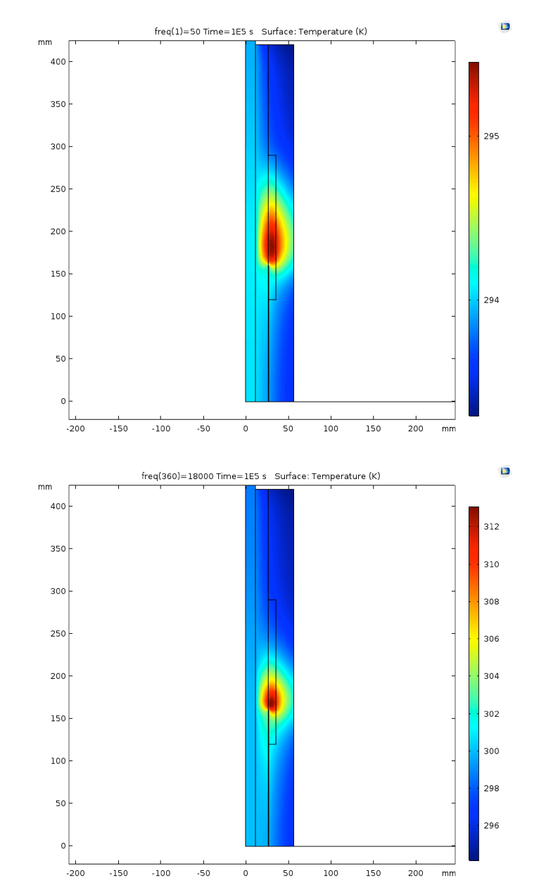
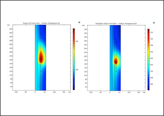
Fig. 5 presents the result of voltage application of different frequency and resulting temperature increase in the field control structure. It can readily be seen that at a frequency of 18 kHz, maximum temperature in the field control layer increases from 293 to approximately 312 K – yielding a temperature rise of 19 K above ambient. In addition, it should be noted that in these simulations, current flowing through conductor was assumed to be 0 A (i.e. no heating from the conductor). By comparison, the respective temperature rise at a frequency of 50 Hz was in the range of 3 K.

Summary & Conclusions
The influence of frequency on field distribution in the vicinity of field control arrangement was studied for a cable accessory with geometric and refractive field control. For materials with the parameters given (see Table 1), field distribution was independent of frequency for the geometric arrangement while the opposite was observed in the case of the refractive arrangement. Based on simulated field changes, temperature rise was calculated for the refractive arrangement. Clearly, there is no temperature increase due to increased field for the geometric arrangement and such arrangement would therefore be more suited for use in a network contaminated with harmonics. However, there will be a certain amount of energy dissipated in the material since the dielectric loss also depends on frequency. This is less significant compared to the case of resistive field grading, where the loss is increased both by the frequency and the square of the electric field. These results are in line with findings from similar past research.
Discussion
During calculations, frequency of voltage was increased in steps. Each field and temperature distribution was calculated for one frequency only. To complete the model, it is advisable to superimpose harmonics of different frequency and amplitude onto the base frequency signal, which would result in more accurate estimation of temperature. Moreover, the characteristics of simulated materials have to be measured in detail in order to complete the model. This would allow better understanding of electric field and temperature distribution in the refractive layer when stressed with high frequency.
It is especially noteworthy that higher harmonics is a relatively new type of stress factor that is becoming more and more present in contemporary power networks. Networks that are highly stressed by harmonics will exhibit increased ageing rates and, as such, their components may not reach the assumed full service life. This represents a further challenge to be accounted for when considering reliability of future MV networks.

References
• Subramanian, A. Sahoo, S. Manohar, S. Panda – Voltage and Current-Harmonics Induced Ageing in Electrical Insulation, 2017 International Symposium on Electrical Insulating Materials, Toyhashi, Japan, September 2017
• Kerry D. McBee – Transformer Aging Due to High Penetration of PV, EV, Charging, and Energy Storage Applications, 9th Annual IEEE Green Technologies Conference
• IEC 60505 – Evaluation and Qualification of Electrical Insulation Systems, CENELEC, Brussels, 2011
• Koltunowicz, G. Bajracharaya, D. Djairam, J.J. Smit – Modelling of Fast Transients Using a High Frequency Transformer, 2009 International Symposiom on High Voltage, ISH, Cape Town, South Africa, September 2009
• Paulsson et al – High-Frequency Impacts in a Converter Based Back-to-Back Tie; The Eagle Pass Installation, IEEE transaction on Power Delivery, Vol. 18, No. 4 October 2003.
• B. Warder, E. Friedlander, A. Arman – The Influence of Rectifier Harmonics in a Railway System on The Dielectric Stability of 33-kV Cables, Proceedings IEE, Vol. 98, 1951, pp. 399-421.
• D. Patil, W. Z. Gandhare – Threat of Harmonics to Underground Cables, 2012 Students Conference on Engineering and Systems, Allahabad, India, March 2012
• Koltunowicz, G. Bajracharya, D. Djairam, Muhannad Al-Suhaily, J.J. Smit – The effects of Prolonged Exposure of Paper insulation to Fast Repeating Transients, 2011 Electrical Insulation Conference, EIC, Annapolis, Maryland, USA, June 2011.
• Cavallini, I. Ghinello, G. Mazzanti. G.C. Montanari – Accelerated Capacitor Degradation due to Nonsinusoidal Voltage Supply and Relability of Insulation Systems, 8th International Conference on Harmonics and Quality of Power, Athens, Greece, October 1998
• CIGRE TB 703 – Insulation Degradation Under Fast, Repetitive Voltage Pulses, WG D1.43, September 2017
• Sonerud, T. Bengtsson, J. Blennow, S. Gubanski – Dielectric Heating in Insulating Materials Subjected to Voltage Waveforms with High Harmonic content
• Lewarkar, D. Bergsma, J. Conradie, S. Buddhawar – Study of Electric Field Grading Types on Medium Voltage Polymerics and Paper insulated Cables
• Kreuger – Industrial High-Voltage, Delft University Press, Delft 1992, ISBN 90-6275562-3
• Ghaffarian Niasar, R. C. Kiiza, N. Taylor, H. Edin, “Effect of Partial Discharges on Thermal Breakdown of Oil-Impregnated Paper”, IEEJ Transactions on Electrical and Electronic Engineering, 2015, S14–S18.
• Patel, Shesha H. Jayaram, A. El-Hag, R. Seetahpathy – MV Cable Termination Failure Assessment in the Context of Increased Use of Power Electronics, , 2011 Electrical Insulation Conference, EIC, Annapolis, Maryland, USA, June 2011.
• Online Comsol manual: https://www.comsol.com/model/cable-tutorial-series-43431, last visited in May, 2019.