Quality is a measure of excellence and benchmarked in the electrical power industry using a variety of national or international standards such as ANSI, IEEE, IEC, ASTM, etc. While meeting these standards is of course critical, most have come to recognize that standards these days have come to represent only minimum performance requirements in an application. For this reason, manufacturers as well as users are looking to further differentiate product quality using enhanced specifications. Quality is also about manufacturing. In this regard, standards and continual process improvement focus on controls and repeatability with the goal of zero defects. Ultimately, quality has to represent product capability and longevity in addition to compliance with basic standards and customer specifications.
This edited contribution to INMR by Edward Niedospial, Technical Director–Transmission at MacLean Power Systems discusses these concepts when it comes to the production of insulators made of toughened glass.


The manufacture of toughened glass insulators can be considered as comprised of two key steps: manufacturing the glass shell; and then assembly of metal fittings onto that shell. Production requires specialized equipment and only a few manufacturers worldwide have the resources and experience to carry out both steps in a single production facility. In this regard, it is useful to study quality not only as it relates to manufacture of the toughened glass shell but also later during final assembly of the insulator.
CLICK TO ENLARGE
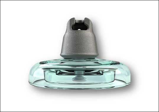
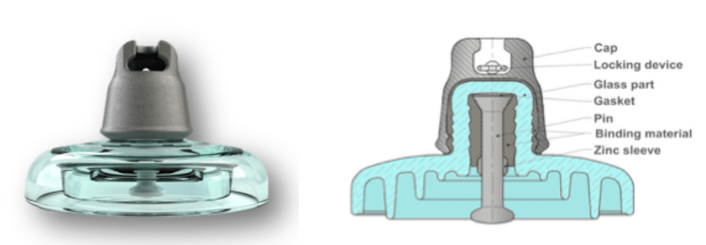
The toughened glass shell comprises the actual insulator. While the fitting assembly and its cementing are important as well, this shell must remain intact over the entire service life in order to assure product functionality. Moreover, once assembled, occurrence of shell breakage not caused by some external event should be rare. For example, general industry expectation is that less than 1 per 10,000 installed units per year should shatter spontaneously. As such, incidence of self-shattering is one aspect of manufacturing that the factory must strive to minimize.
Apart from the critical shell, the hardware components of a toughened glass insulator include:
1. Caps
The cap at the top is a ductile iron socket fitting that has been galvanized and assembled with a stainless-steel locking pin.
2. Pins
The bottom pin fitting is a forged steel ball connection that has been galvanized and coated with bituminous tar. A sacrificial zinc collar can also be added for extended performance, especially in severe service environments.
Clevis/tongue fittings are sometimes used at lower voltages.

Raw Glass & Furnace
Manufacture of the glass shell starts with key raw materials and ingredients, including silica, alumina, sodium carbonate, sodium sulfate, limestone, potash and dolomite. Cullet (sometimes referred to as seed glass) is glass recycled from earlier manufacturing and added to these raw materials to ensure consistency from batch to batch. Mixing of these materials is specific to each manufacturer and sees minor variations in elements that are mined from local sources or used in the furnace. These natural variations in minerals account for the slight difference observed in hue of the glass insulating shell.
Furnaces are typically large-scale with capacity exceeding 100 tonnes. For consistency, it is important to maintain the temperature and also to regularly monitor the chemistry of the output as well as of the mix of raw materials being fed in. The furnace is the first possible source of inclusions – imperfections in the glass that can eventually cause spontaneous shattering. For example, over time refractory bricks may begin to sluff off material into the glass mix. Furnaces must therefore be shut down for maintenance every few years and be re-lined.
Forming of Shell
This takes place on an automated press with a precise amount of molten glass gob inserted into the mold cavity and pressed (see Fig. 2). The dimensions of each particular shell, i.e. height and diameter, are defined by standards but geometry and shell profile can differ from one supplier to the next.
CLICK TO ENLARGE
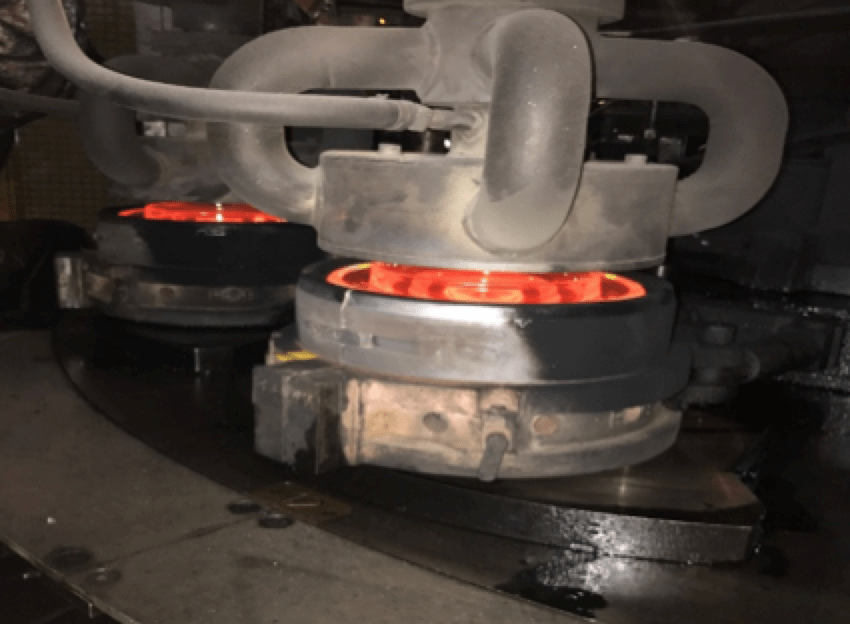
Any product markings on the shell are from tooling and will also vary by supplier. For example, shell markings on insulators typically include:
- M&E rating (see Fig. 3);
- Product ID;
- Cavity #;
- Date code;
- Factory ID.
CLICK TO ENLARGE
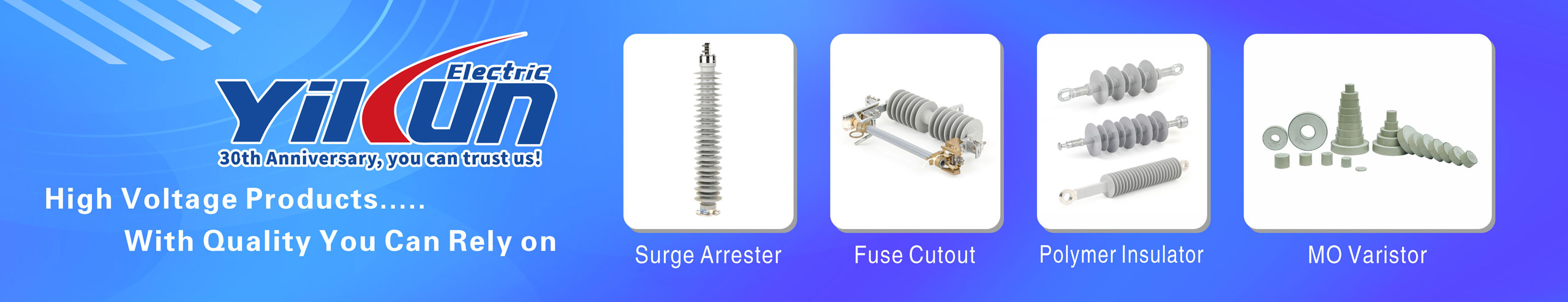
Toughening Process
After forming, the shell goes through a special process whereby it is transferred from the press to a toughening line, passing through a homogenization furnace to keep the glass at constant high temperature (see Fig. 4). Glass toughening is accomplished by rapidly cooling the hot glass using compressed air at key locations along the shell to achieve uniform cooling (see Fig. 5). This results in the glass having a hot center temperature but a relatively cool surface. Glass structure after toughening sees the center in tension while the surface is in compression and this increases mechanical and electrical resistance as well as durability of the glass insulating parts. Achieving uniformly high quality in this critical step requires a highly automated and carefully controlled materials handling process.

CLICK TO ENLARGE
CLICK TO ENLARGE
Thermal Cycle
After toughening, shells are transferred through a prescribed thermal cycle, where they are thermally shocked with the goal of extracting potentially defective shells. The shells are heated to about 300°C and then dropped into cold water, effectively dropping temperature of the glass to 120°C (see Figs. 6 & 7). Insufficiently toughened glass shells will collapse from the sudden thermal shock. Every shell is thermally tested at least once and, if required, the entire process can be repeated. The thermal shock cycle is essentially a key quality check inasmuch as any shell that pops is a ‘No Go’ while shells that survive are a ‘Go’. Those glass shells that collapse during thermal cycling are recycled, with fragments collected and added back to the production process in the form of cullet (seed glass).
CLICK TO ENLARGE

CLICK TO ENLARGE
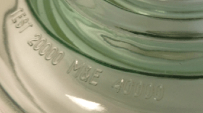
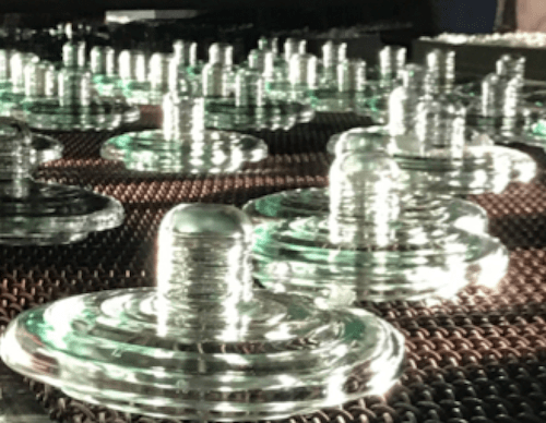
Operation of the furnace is ’24/7′ and therefore faster than the assembly process. For this reason, completed shells are held in stock until ready for assembly. Cap & Pin Assembly Glass shells are cemented into the caps while the pin and zinc sleeves are cemented into the shell with alumina cement. Here again automation is utilized to ensure a precisely measured amount of cement and achieving precise length tolerance. The cemented assembly is then cured by cycling through an hour-long bath in water at about 70°C. After curing, every toughened glass insulator is subjected to electrical and mechanical routine testing as well as final visual checks.
- Routine electrical test: continuous flashover for 4 minutes;
- Routine mechanical test: held at 50% of SML rating for >3 sec.

Sampling tests are then carried out on each assembled lot of insulators. This includes verification of all critical dimensions, socket/ball gauge compliance, verification of locking system, galvanizing check, M&E test and impulse puncture test.
Validation & Test Reports
Finished insulators are subject to design or qualification testing per industry standards, including ANSI C29-2B, IEC 60383, CSA-411-1-16, and GOST 6490-93. Customers can also add additional test criteria above and beyond these standards to their specifications to further qualify final insulator performance.
Test reports for each insulator design should be specific to the factory where the insulator is manufactured. If a supplier has two factories producing the same insulator type, there should be separate design/qualification reports for each insulator specific to the plant where it was made. For products assembled at another location, test reports for these should include reference to which factory made the shell. If the toughened glass shells come from two factories, that should dictate separate test reports (i.e. specific to the factory which manufactured the shell).
Conclusions
When considering quality of a toughened glass insulator, evaluation and qualification should be thorough and include every aspect of production. There should be extra attention to where the toughened glass shell is manufactured and also to how that process is maintained to prevent defective shells from ever being used in assembly of finished insulators. This is because, while assembly of the cap and pin is important, quality of the toughened glass shell will have greater impact on long-term insulator performance. Test reports should be specific to the factory at which the insulator is produced but should also reference where the shell has been manufactured. This would require specific factory markings. At a minimum, the toughened glass shell should have markings molded into its body, including M&E rating, lot code reference and factory identification (ID). These markings should be legible and permanent. The ID of the factory where the insulator is assembled should be marked on the cap of the insulator – also legible and permanent. Even when made in the same factory, having such markings on both the shell and the cap helps identify when the shell was made and when it was assembled. Adding factory ID markings to the shell is simple, with little impact on product cost yet it brings a higher level of quality assurance for the insulators. The various industry standards (e.g. ANSI, IEC, CSA) do not specifically call out for factory ID on a shell but perhaps should.