Live line work is becoming a much more important factor when conducting effective and efficient line work, whether erecting new lines or when refurbishing existing ones. Since this type of work is often performed either on or in the vicinity of line insulators, it is important to establish the level of insulation necessary to work under these conditions.
In order to safely apply these work methods, it is imperative to conduct inspection of the insulators using appropriate tools and proper test methods. Power line workers must also abide by important rules that establish the minimum distance that they can approach any energized component of the line.
This edited contribution to INMR by A.J. (Tony) Carreira of K-Line Insulators discusses key aspects of this topic.

It has previously been well documented that live line work (LLW) is a work practice that is here to stay but that is flourishing. These methods are important to many utilities in the maintenance of their systems. Utilities and insulator suppliers have worked together diligently to establish good inspection and work practices that permit conducting LLW with all insulator types.
Various international technical organizations have noticed this growth in demand for live line work and have previously established a number of working groups, tasked with setting standards or providing guidelines for use by utilities and contractors.
When conducting live line work on or in the vicinity of insulators, it is imperative to determine the electrical condition of those insulators before any such work is performed. This tenet applies to all types of insulators, whether polymeric, porcelain or glass construction.
The typical LLW performed on line insulators is common for all insulator material types. While their may be minor variations for some procedures, this type of work is usually very similar. A majority of the LLW conducted on insulators is restricted to suspension and dead-end/strain strings. This discussion will thus address these designs for all material types.
General Overview
The activities related to work with or on any insulator on a power line involves their installation or maintenance. These particular activities can be performed under energized or de-energized conditions. Undoubtedly, extra precautions, equipment and work procedures will be more complex when any of this type of work is to be performed under energized conditions. While there may be some differences to consider when conducting such work on glass, porcelain or polymeric insulator designs, there are also many similarities.
Generally-speaking, live line work of any insulator type should only be conducted under dry, fair-weather conditions. This type of work activity should never be undertaken when there is a possibility of lightening or rain anywhere in the vicinity of that work.
When planning to perform LLW on or in the vicinity of insulators, it is necessary to first determine the existing electrical withstand level of those insulators. For LLW purposes, the evaluation of insulator damage that could affect its electrical performance is limited to determining if the condition of the insulators is safe for the duration of the work period for that day only. In this case, the evaluation is NOT intended to determine electrical end of life (EOL) of the insulator.
There are currently accepted work practices and diagnostic devices available to ensure that LLW is conducted safely with any insulator type. Visual inspection is the most common method used to identify most potential electrical defects found on insulators. In some cases, these are obvious, but not always. There are other forms of electrically sensitive damage requiring not only appropriate visual inspection, but also inspection using diagnostic devices.
Diagnostic tools available for such use facilitate inspection for:
• Corona discharges (non-contact)
• UV radiation (non-contact)
• Thermal radiation (non-contact)
• Electric field distortion (contact)
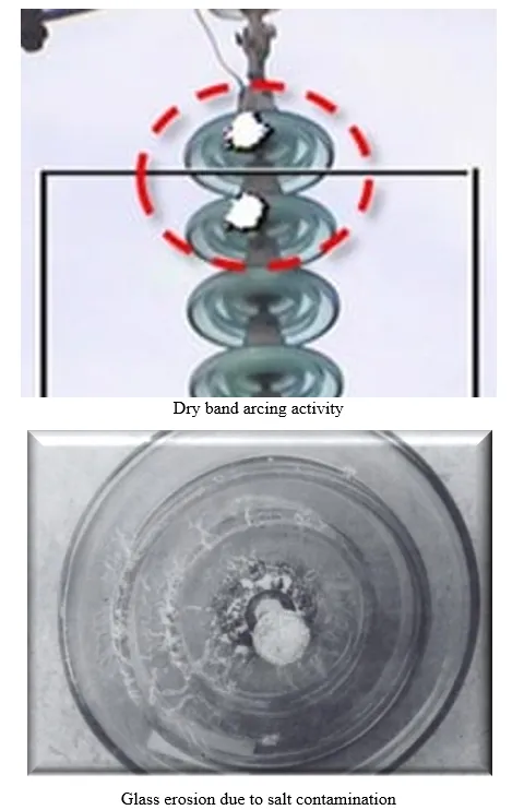
Some tend to believe that it is only necessary to test polymeric insulators prior to conducting LLW. However, to ensure the safety of every operator, at all times, it is necessary to inspect and test all insulator types first, before conducting any form of live line work. This is a particularly important factor to consider since the replacement of broken glass (Fig. 1) and porcelain insulator units is one very common reason utilities need to conduct live line work. This is in fact a frequent event requiring a relatively high use of human and financial resources in a utility’s maintenance and inspection activities.
This insulator replacement activity results in line crews being more frequently exposed to this type of LLW. A presentation by Kinectrics included the following insulator performance statistics, based on a 1999 CIGRE survey:
• Polymeric insulator failure rate = 0.52 failures per 10,000 insulators.
• Ceramic/Glass failure rate = 0.5 to 1.5 failures per 10,000 insulators.
The data would indicate that the failure rate of glass and ceramic cap & pin insulators could go much higher than that of polymeric insulators. Defects in porcelain and glass insulator types that may require, not only visual, but additional diagnostic inspection include:
• Puncture
• Fracture of the ceramic materials
• Erosion and tracking
• Dry band arcing
• Contamination
Another interesting fact was established during testing at one of the Canadian utility’s research facilities in 1978 [6]. This work demonstrated that the withstand levels of glass strings with damaged insulators were consistently lower, by a minimum of 10%, compared with corresponding withstand levels of porcelain strings.
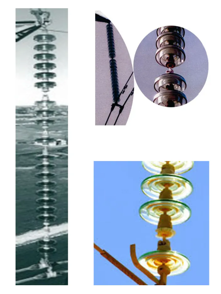
Some proponents of glass insulators promote the notion that glass units do not require any type of inspection or testing prior to LLW. The premise used by such proponents for this is the claim that “a glass bell is either there or it isn’t”. Assuming glass insulators do not require proper inspection is not only a bad decision but can also result in an unsafe outcome.
Some examples of suspect glass insulator units that have not disintegrated are illustrated in Fig. 2.
Appropriate electrical inspection is always necessary to determine if sufficient insulation remains in a string of either glass or porcelain insulators or in a polymeric insulator to conduct live line work safely. Prudent and safety minded utilities always inspect and test all insulator types before conducting LLW.

Live Line Work in Vicinity of Ceramic Insulators
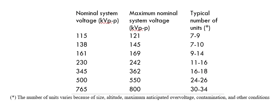
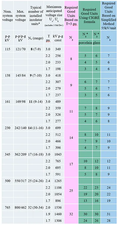
When considering the possibility of conducting live line work on or in the vicinity of a ceramic (glass or porcelain) insulator string, it is necessary to determine the insulation value of that string. To make this determination, it is first necessary to establish how many insulators are being used in the given system. Fig. 3 provides a range of the typical number of discs used in a string for various system voltages on transmission lines.
Once the number of units used on a system voltage is established, it is then necessary to determine how many of those are in a “healthy” electrical condition before conducting any form of live line work. This analysis is performed to determine the minimum number of non-defective units that would be required to provide the insulation value needed to withstand any overvoltages that could occur on the line.
System Overvoltages
System overvoltages (SO) impact the ability to conduct live line work. There are typically two types of potential overvoltages that could be imposed on the line. One form is the result of lightning and the other can occur during switching operations. While we need to be aware of both types, lightning overvoltages are usually not considered since live line work is not normally conducted under inclement weather conditions. As a result, transient switching overvoltages are thus the most important insulator electrical stress of concern when conducting live line work.
The characteristics of a transient switching overvoltage that affect insulator stress include its waveshape and polarity. The positive polarity of a surge voltage usually has the lowest sparkover magnitude and is typically used to determine the required insulation value of a ceramic insulator string under which live line work can be conducted.
Number & Location of Defective Units
The number and location of defective ceramic units in a string both play an important role in the withstand voltage of that given string.
Obviously, the more defective units that exist, the lower the withstand capability of an insulator string. What may be less intuitive is how the location of a defective bell or unit might affect the ability of that string to withstand a transient switching overvoltage. Defective insulators positioned near the middle of the string length result in the lowest reduction in dielectric resistance to these overvoltages. Damaged units situated at the energized end of the insulator string will have the highest reduction in resistance to switching overvoltages. Faulty ceramic bells located in the vicinity of the unenergized end of the string will have an intermediate resistance to switching overvoltages.
Work Methods, Tools & Other Conditions Impacting LLW in Vicinity of Insulators
Various work methods and tools are used when performing live line work in the vicinity of ceramic insulator strings. In most cases, when working in the vicinity of or on insulator strings, it is common to jumper and short out a few insulator bells at either end of the string. Doing so, results in minimizing slight shocks resulting from existing charging currents. The shorted units must be included in the count of “defective” units in a string, when considering live line work. These units are in effect, providing little or no insulation value to the string.
When the live line work method involves the integration of live line tools to complete the assigned task, it is imperative to consider the impact these tools will have in potentially reducing the effective safe live line workspace. When a tool is introduced into the workspace it must be recognized that it can contribute to a further reduction in the switching overvoltage withstand strength.
There are other conditions that will not only affect how many ceramic insulator bells are initially installed on a line for each voltage system but also how many healthy bells are required to allow LLW. Examples of these other conditions include land elevation and contamination levels, to mention a few.
Determining Minimum Number of Good Ceramic Insulators in String for LLW
As previously mentioned, on transmission lines, the transient switching overvoltage is the fundamental criterion used to establish the ability to safely conduct live line work tasks. It is therefore essential to determine the insulation level required to withstand an expected transient switching overvoltage in order to safely conduct LLW on or in the vicinity of a ceramic insulator string.
IEEE Switching Overvoltage Calculation
According to IEEE, to calculate the required insulation level, it is necessary to first determine the reference peak phase-to-ground AC voltage (Vp-g). This value is obtained by converting the maximum nominal phase-to-phase voltage (Vp-p∙max) to peak voltage (phase-to ground), where:
Vp-g = √2*(Vp-p•max/√3) (kV) (1)
The application of a factor (T) to this reference peak voltage will result in establishing the expected maximum switching overvoltage for a given transmission line. This equation is:
Vso-max = Vp-g*T (kV) (2)
“T” is defined as the Maximum Switching Overvoltage Factor. Industry accepted values to use for T, when conducting live line work include:
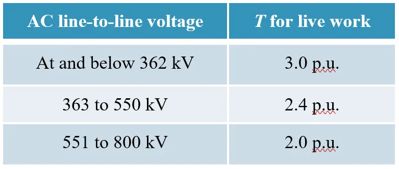
It is possible to use lower “T” values than those included in Table 1, above. For example, one utility uses a T value of 2.0 p.u. instead of 2.4 p.u. for LLW on their 500 kV system. Their studies confirmed that by establishing a reclosure hold-off during all live line work activities, they can limit their maximum switching overvoltage to this level. Protective gaps can also add another dimension to the safety factor.
The following is a sample calculation to illustrate the determination of an expected maximum switching overvoltage for a 230 kV system, where:
Vp-p•max = 242 kV (from Fig 3. above)
To calculate Vso-max, it is first necessary to determine the reference peak AC voltage, as follows:
Vp-g = √2*(242/√3) = 197.6 kV (3)
From this value it is then possible to establish the expected maximum switching overvoltage.
Vso-max = 197.6*3 = 592.8 kV (4)
where the factor T = 3 (from Table 1 above)
CIGRE Formula to Calculate Required Number of Good (Healthy) Insulators
One method to calculate the insulation value of a ceramic insulator string is to use the CIGRE Formula. This formula is as follows:
Ub = Uo * (1 – 0.8*[Nb/No]* k) (5)
where:
Ub is the 50% disruptive discharge voltage of an insulator string with Nb defective units.
Uo is the 50% disruptive discharge voltage of the same insulator string with all No healthy units.
Nb is the number of defective units in the string.
No is the number of units in the string.
k is the empirical coefficient that characterizes the average dielectric strength of defective units.
In studies conducted by various entities, it has been determined that a damaged porcelain insulator bell will have a higher withstand level than a glass insulator bell. This is strictly based on the assumption that if a glass bell has full disintegration it has no insulation value.
As previously noted, one laboratory conducting this investigation and testing for a utility, concluded that the withstand levels of porcelain strings were consistently higher than that of glass strings. When using the CIGRE Formula to calculate the required number of healthy insulators it is necessary to factor in this condition. This is addressed by including the above noted, empirical coefficient ”k”, where;
k = 1.00 for broken glass insulators
and
k = 0.75 for broken porcelain insulators
The above parameters for this coefficient basically establish that broken glass insulators have no insulation value. It has also been determined that porcelain insulators can have between 0% to 100% of insulation value depending on the amount of damage or lack thereof. As a compromise, it has been assumed that the typical remaining insulation value of porcelain will be about 25%. The necessary number of required good insulators to allow safe application of live line work can be determined by using the following equation:
Ng = No – Nb (6)
where:
Ng is the required minimum number of good insulators
The following is a sample calculation of the required number of good insulators necessary to conduct safe live line work for a 230 kV transmission line with 14 standard size bells per insulator string.
The following assumptions are used in this calculation:
T = 2.2 pu
and
Ub 2.2pu = 512 kV (for T = 2.2 pu)
It is now possible to solve for Ng for a porcelain insulator string as follows:
Nb 2.2pu = (14/[0.8*.75])*(1-512/699)
or
Nb 2.2pu = 6.242 or 6 max. allowed defective units
and
Ng 2.2pu = 14 – 6.242 = 7.76 or 8 required good units
The results for a glass string of insulators under the same conditions would be:
Nb 2.2pu = (14/[0.8*1.00])*(1-512/699)
or
Nb 2.2pu = 4.68 or 4 max. allowed defective units
and
Ng 2.2pu = 14 – 4.68 = 9.32 or 10 required good units

Simplified Approach to Calculate Required Number of Good (Healthy) Insulators
As an alternative to the above more complex calculation method, some prefer using what has been established as the Simplified Approach to calculating the number of required healthy insulators. This method of calculation is based on the above work but assumes that each healthy disc has a universal dielectric withstand strength of 55 kV.
The equation used to calculate the number of allowed defective insulators using this Approach is as follows:
Nb = (Uo – Ub) / 55 (7)
Using this method to calculate the required number of good insulators for the same parameters used above, yields the following results:
Nb 2.2pu = (699-512)/55 = 3.4 or 3 bad units
and
Ng 2.2pu = 14 – 3.4 = 10.6 or 11 required good units
Undoubtedly, the results obtained using the Simplified Approach are more conservative than those obtained using the CIGRE Formula for glass insulators and even more so for porcelain units. Table 2 summarizes the various parameters used by IEEE to establish the minimum number of healthy insulators required for live line work.
Various papers published by global standards organizations, utilities and individuals have provided very similar required numbers of healthy insulators to safely perform live line work on other system voltages.
Some publications go into more detail on other conditions to be considered when establishing the required number of healthy ceramic insulator units, such as:
• whether the string is in strain or suspension
• whether other limiting devices are used such as:
• resistors (to reduced trapped charges)
• blocking reclosures (no re-energization)
• portable protective air gaps or PPAG (limit SO to gap settings)
• live line work method being used:
• barehand
• live line sticks
• work platforms:
• ladders
• line carts
• aerial devices

Insulator Inspection & Testing
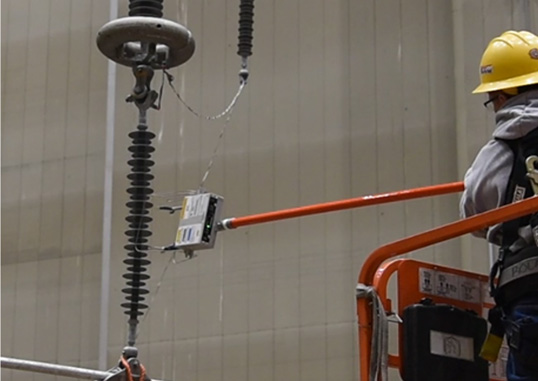
There are various methods available to inspect and test both ceramic and polymeric insulators. This topic has been adequately covered in various publications. An example of a test device for use with ceramic insulator bells is a portable meter which applies a 10 kV DC voltage across a ceramic insulator bell using two metal probes (Fig. 4).
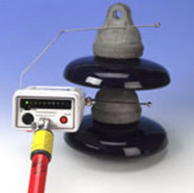
This device can be used on any system voltage and the line can be energized or de-energized. Two types of meters are available. One type, measures current while the other measures resistance. In the former case, a leakage current reading greater than 2 µA is considered defective. In the latter case, ceramic units with a resistance reading greater than 2 GΩ are deemed to be healthy. There are currently, at least a couple of test devices, being used to determine the health of polymer insulators. One of these units was designed to measure the electric field along the insulator under test. The device and a demonstration of its application is included in Fig. 5.
The evaluation criteria using this method is to compare those results from the sample under test to the electric field profile of an equivalent reference healthy unit. This is demonstrated in Fig. 6.
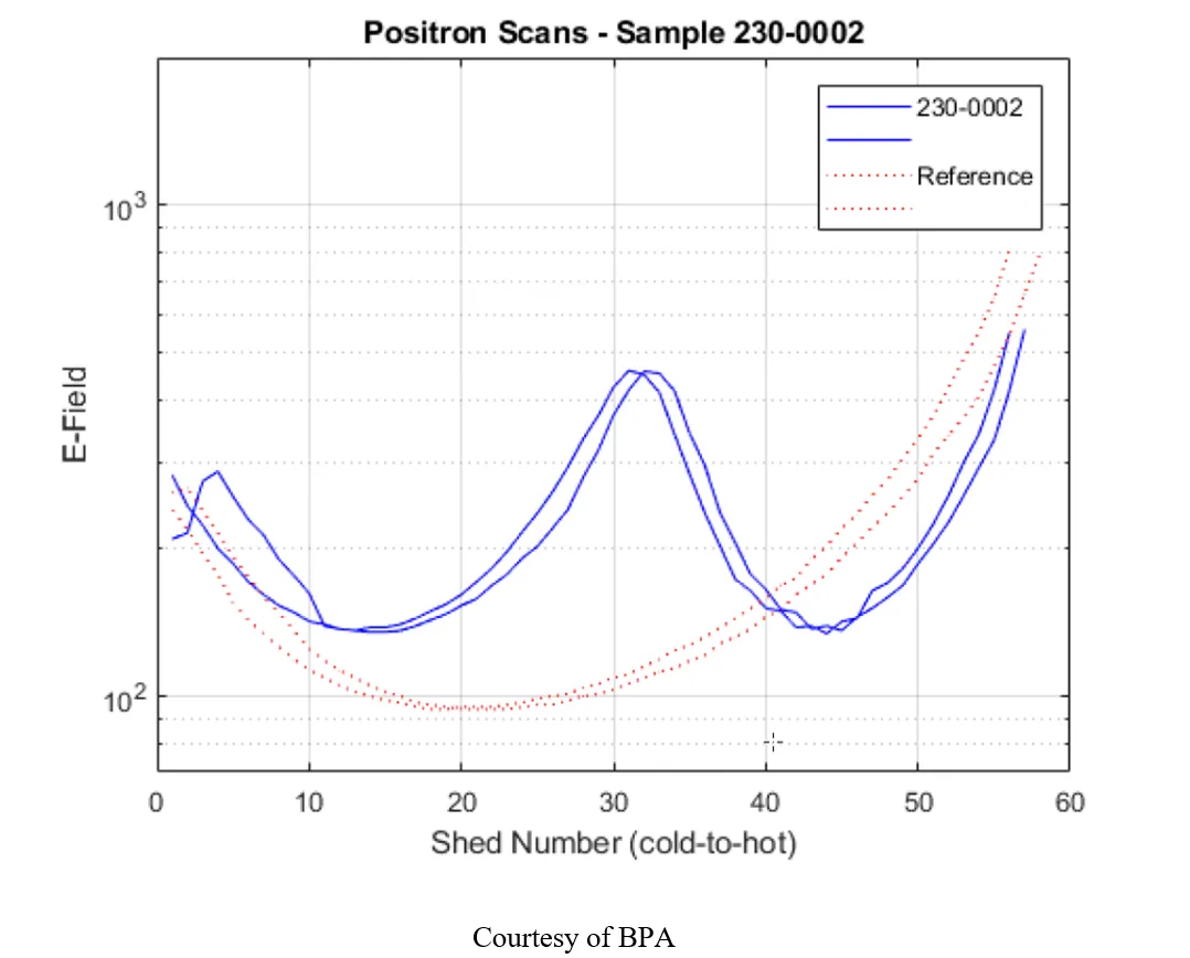
The proponents of this device claim that it can also be used to measure the electric field along a ceramic string of insulators in the same manner as for a polymer insulator.
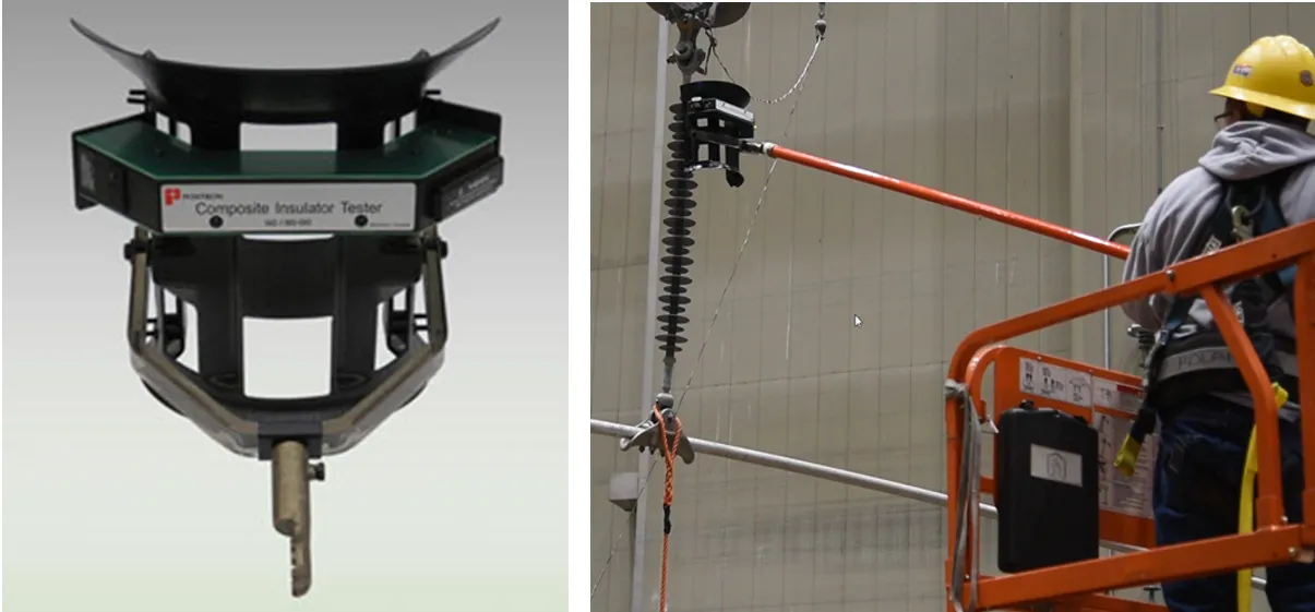
The second device discussed here, was originally developed by EPRI (Fig. 7). This tester is designed to identify any conducting defect as well as its length and location.
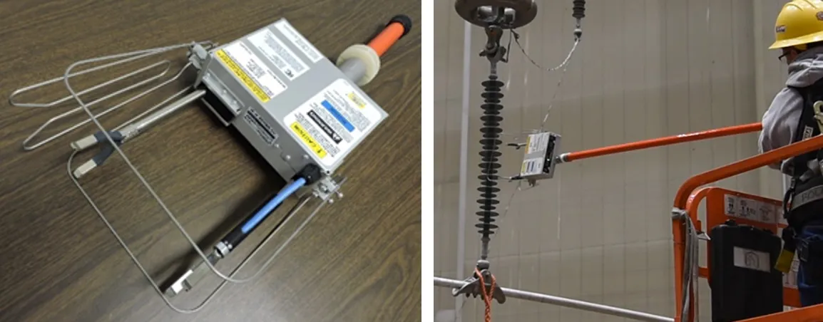
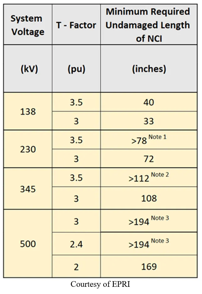
The test method using this device includes a Guide (Table 3) that identifies the minimum good insulation length required of a polymer unit when planning to conduct live line work on it or in the vicinity. This information is provided for various transmission voltage systems and selected T-factors.
There are a variety of other work methods and devices available that are used for testing polymer insulators that are not covered in this document. Efforts are ongoing intended to improve the information and methods available to test and demonstrate the efficacy of a ceramic insulator string or polymer insulator. As an example, a new ESMOL subcommittee was recently established to develop a Guide for Testing of Insulators Prior to Energized Work.
Guide content is planned to include testing of glass and porcelain information from existing guidelines as well as recommendations for polymer insulators so that all the information will be contained in a single document.
An IEEE Project Authorization Request (PAR) was prepared for this work and was submitted for approval at the Sept 2022 RevCom meeting. This work is expected to be completed by June 2026.

Calculations of Minimum Approach Distance (MAD)
The minimum approach distance used during live line work is defined as the space or gap that must be maintained between any part of the line worker’s body and any line component at a different electrical potential to the worker. This space must also be maintained to any object the line worker maybe handling to conduct that work. This does not include live line tools.
The criteria typically applied in establishing MAD includes various steps and calculations. The first step is to identify the task to be performed and the work method to be used. Most of the live line work performed on transmission lines is conducted near the structure and usually in the vicinity of, or on the insulators themselves.
As has been detailed in this paper, once the work task has been identified, it is then necessary to determine the maximum switching surges to which the given line may be exposed. This information then allows calculating the minimum required insulation withstand level to permit live line work. In so doing, it is imperative to consider the condition of each ceramic insulator bell or polymer insulator and any expected inadvertent movement the line worker may have to make in order to accomplish the task at hand.
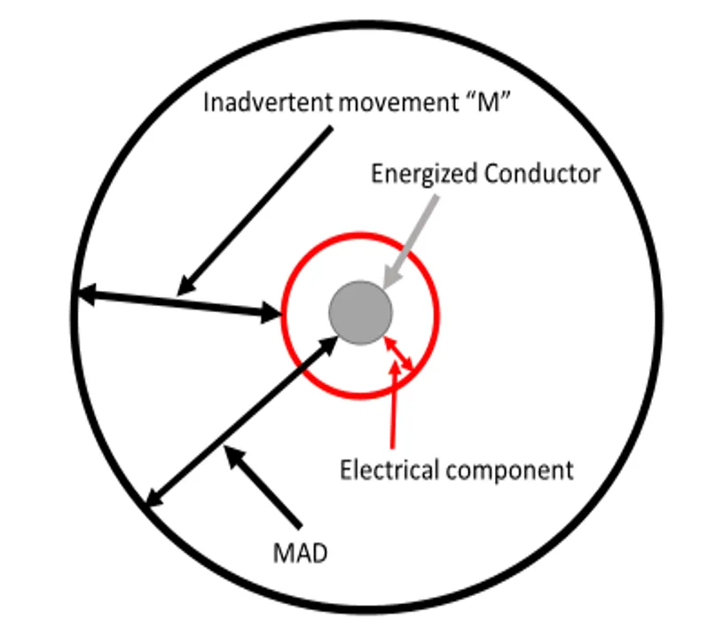
When calculation MAD, it is necessary to factor in the required electrical separation spacing as well as the potential inadvertent movement distance. A graphical depiction of these contributing components is illustrated in Fig. 8.
The calculation methodology for MAD is quite well established by IEEE. The following example to determine MAD for a 230 kV AC line is based on this method.
First, it is necessary to establish the maximum line-to-ground voltage (VL-G) for a 230 kV system, followed by calculating the maximum possible peak line-to-ground voltage (VL-Gpk). In this example, VL-L = 242 kV, therefore:
VL-G = VL-L/√3) = 242/√3 = 139.72 kV
VL-Gpk = √2*(VL-G)*T = √2*139.72*3.0 = 592.78 kV
One of the factors to consider when calculating MAD is the switching surge air saturation factor (a). This adjustment factor is used to compensate for any air saturation. This value is determined as follows:
a = (Vpeak – 635)*0.00000714 (8)
= (592.78 – 635)*0.00000714
= – 0.000301438
NOTE: When a < 0, then a = 0
In this example, the air saturation factor does not affect the necessary MAD value. This result can now be used to determine the minimum approach distance for this example using the following equation:
DMADL-G = ((C1 + a) * T * VL-G * A) + M (ft) (9)
The maximum switching overvoltage factor selected for this example is T = 3.0 p.u. This factor was selected on the basis that a hold off would be established preventing re-closing operations.
The following other parameters can be found in the above referenced document:
• M – Factor for inadvertent motion: M=1ft
• C1– 60 Hz rod gap withstand factor = 0.01 ft/kV
• A – Altitude correction factor A=1.02 (for an assumed altitude of 3100 ft)
MAD can now be calculated as follows:
DMADL-G = ((0.01 + 0) * 3 * 139.72 * 1.02) + 1 (ft)
DMADL-G = 5.2754 ft (1.6 m)
Conclusions
The ability to conduct LLW is gaining increasing interest among global utilities as an alternative work method, when planning to perform maintenance activities on a power line.
To utilize LLW methods it is necessary to consider the various aspects which must be addressed in order to conduct this type of work safely and efficiently. Some of these considerations include:
• determining the condition of line insulation
• using appropriate insulator inspection and test methods for each insulator type
• determining LLW methods and tools to be used
• calculating switching overvoltages
• calculating MAD
A proper approach to implementing LLW skills offers utilities and contractors an additional “tool in their work belt” that will complement their de-energized work techniques.
References
[1] A.J. Carreira, “Insulator Inspection”, INMR, Munich, Germany, October 2015.
[2] CIGRE WG B2.64, “Inspection and testing of tools, equipment and training for live-line work on overhead lines”, B2 Technical Brochure, Overhead Lines, Reference: 865, February 2022.
[3] CIGRE WG B2.87, “Live line and vicinity working on overhead lines: Safe Management Guidelines”, (in progress).
[4] A.J. Carreira, “Insulator Inspection”, INMR, Munich, Germany, October 2015.
[5] J. Kuffel, Overview of HV Insulators, Kinectrics presentation, Toronto, Canada, April 2003.
[6] Ontario Hydro Research, “Test report 78-281-H”, Toronto, Ontario, 1978.
[7] ESMOL Subcommittee 15.07, “Minimum Number of Good (Healthy) Porcelain or Glass Insulator Units in a String for Live Line Work”, IEEE Transactions on Power Delivery, Volume:17, Issue: 3, July 2002, Pp 809 – 814.
[8] IEEE Std 516-2021, “IEEE Guide for Maintenance Methods on Energized Lines”, September 23, 2021.
[9] A.J. Carreira, P. Komaromi, “State of the Art Transmission Live Line Maintenance and Techniques, CEATI Report No. T183700-3276, February 2020.
[10] A.J. Carreira, “Non-ceramic insulator condition detection”, INMR, Crete, Greece, May 2009.
[11] A.J. Carreira, et al, “Guidelines for Establishing Diagnostic Procedures for Live-Line Working of Nonceramic Insulators”, IEEE paper number: TPWRD-01176-2012, January 2014.
[12] Kinectrics, “Condition Assessment of In-Service Porcelain Insulators”, INMR Article, March 17, 2023.
[13] D. H. Shaffner, D. L. Ruff, G. H. Vaillancourt, “Experience with a Composite Insulator Testing Instrument Based on the Electric Field Method”, ESMO 2000, Montreal, Canada, October 8-12, 2000.
[14] A.J. Carreira, “Inspection and Testing of Non-ceramic Insulators”, Energy 21C, Melbourne, Australia, September 6-9, 2009.
[15] IEEE, “Guide for the Testing of Insulators Prior to Energized Work”, (in progress).
[16] IEEE/ESMOL, Application of the Minimum Approach Distances at Distribution Voltages, Draft 3, IEEE, February 21, 2019