The height of power transmission towers is usually from 10 to 40 m while the span between consecutive towers is typically between 200 and 400 m. Given this, the area of ground that needs to be considered in any simulation is large and the Finite Element Method (FEM) is not suitable for this application. Instead, the Boundary Element Method (BEM) is ideal for these types of open region problems.
The BEM method is based on discretization of Maxwell’s equations in integral form. Its distinctive strength lies in the ability to achieve a high degree of precision, both locally and across the entirety of the problem domain. Although suitable for open region problems, the BEM method does require a computer with large RAM and CPU power to obtain rapid results. Hence, it is important to develop a BEM formulation that can utilize and benefit from the mirror and/or angular symmetry and/or linear and/or angular periodicity in the model.
This contribution to INMR by experts at INTEGRATED Engineering Software refers to their 3D Electric Field Solver COULOMB™ for the simulation method and results presented, which are confined here to application of Symmetric Conditions.

For many high voltage power transmission models, there exists mirror symmetry about a plane and Symmetric Conditions can be applied to reduce the model size by half. This will reduce solution time by one-fourth versus for the full model without losing any accuracy. Moreover, the time taken will be less to prepare the reduced model to solve.
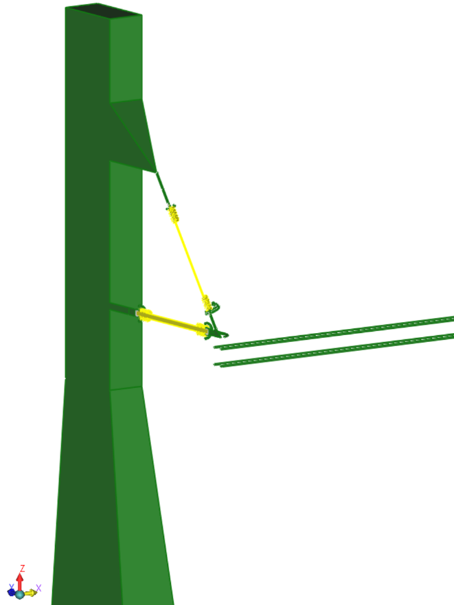
In the COULOMB™ program, Symmetric Conditions can be applied only to the principal planes: X=0, Y=0 and Z=0. Therefore, the model may need to be displaced accordingly. In this program, Symmetric Conditions about the three principal planes can be applied simultaneously. However, it is noteworthy that power transmission models typically exhibit symmetry about one plane or, at most, two planes. Fig. 1a, for example, shows a transmission tower supporting conductors using two insulator strings. In order to estimate E-fields at the insulators and on their associated corona rings, it is not necessary to model all the details of the tower. Hence, the tower shown is modeled as a solid vertical block. This model has mirror symmetry about the X=0 plane and therefore the model is cut by X=0 plane. Only that half in the X≥0 the region is retained (see Fig. 1b).
By applying symmetric conditions about one principal plane, the RAM requirement will be reduced by one-fourth and the solution time reduced by more than half that required for a full model. Fig. 2 shows the electric field arrow plot on the surface of the corona ring.
In the model shown in Fig. 3, mirror symmetry exists about X=0 and Z=0 principal planes. By applying Symmetric Conditions about two principal planes, the RAM requirement is reduced by one-sixteenth and solution time reduced by more than one-fourth versus that of the full model.