Station class arresters since 1980 have been based around various types of metal oxide varistors. Despite having been designed to withstand most power system surges, it is still possible for these varistors to become overloaded or fail such that fault current will flow through the arrester’s core. Since this is an expected event over its life cycle, the arrester is designed to both conduct and withstand fault currents at significant levels and not fracture violently risking collateral damage to nearby equipment. In this regard, it is important to assess if arresters are suitably rated for the system to which they are being applied. This edited contribution to INMR by Jonathan Woodworth explained the basic concepts in this regard.
Below are basic principles to note:
1. Fault (or short circuit) current is not the same as lightning current but is rather the current that flows from the power system when there is a short circuit. If the short circuit is within the arrester, this is understood to be an arrester-conducting fault current.
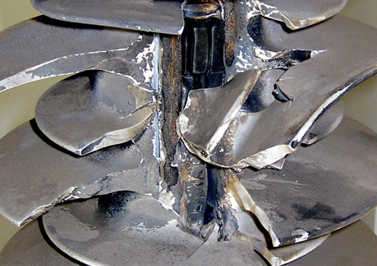
2. Violent rupture of an arrester is not caused by lightning current but rather by gases created when fault current heats up and vaporizes materials within the housing. Lightning current can lead to fault current but, without fault current flowing, there would not be a
3. Arresters are designed to conduct lightning current multiple times over their service life and these operations do not generally result in failure or If an arrester operation does lead to failure, it will likely become a very low impedance path to ground and result in fault current flowing.
4. Arresters are designed to conduct fault current one time at their end of life. Applying fault current to an arrester a second time, such as from reclosing a circuit, can result in violent rupture.
5. When selecting an arrester for a new or old application, it is important to check that the fault current available at the arrester’s location is compatible with the unit’s fault current withstand rating.

As with all critical arrester parameters, fault current withstand capability is verified by testing at high current laboratories. The relevant test procedure is found in the latest standards and the arrester tests are identical for both IEEE and IEC. To determine fault current withstand capability, the fundamental test procedure is to apply the specified fault current to the arrester, which is expected to take this current for the full duration without interruption.
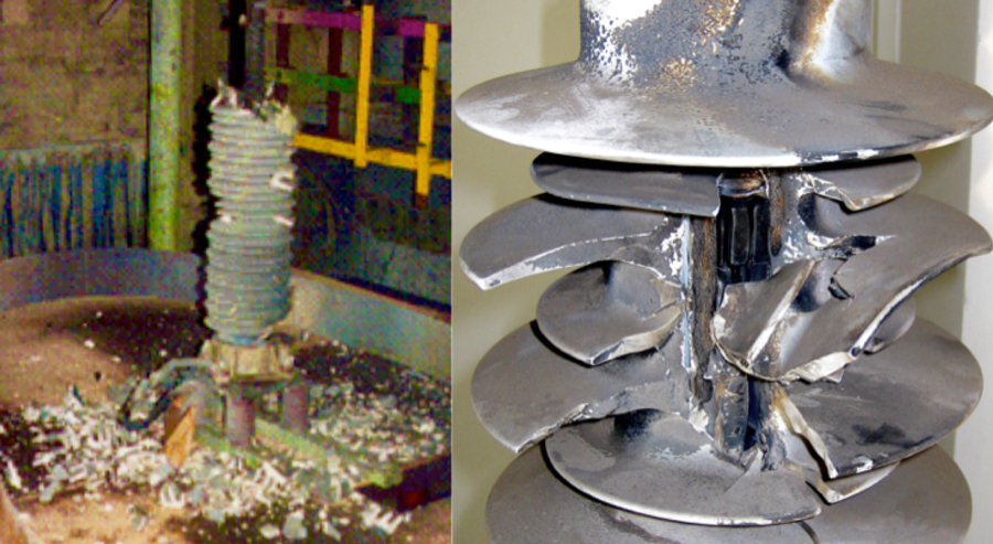

The arrester is permitted to fracture but parts cannot be expelled beyond a limit equal to a circular area with a diameter twice the unit’s height. Per both standards, all arresters must have a fault current or short circuit rating and must be tested at two or four current levels depending on their design.
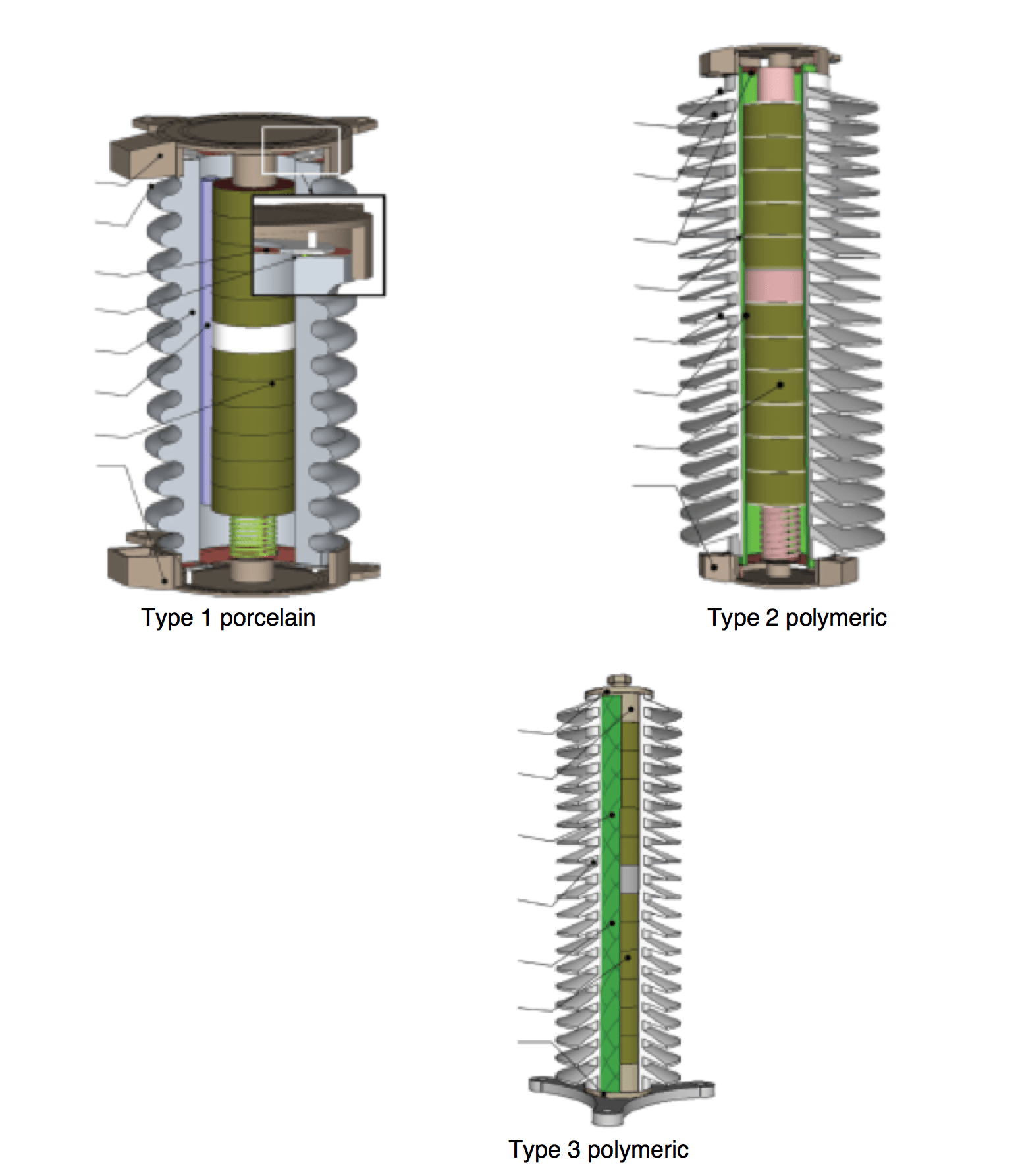
Arrester design A (Type 1 and Type 2) has substantial internal air volume while design B (Type 3) has no measurable internal air volume. The test currents most often used for design A station class arresters are: 63 kA, 25 kA and 12 kArms for 12 cycles and at 600 amps +/- 200 ampsrms for 1 second (peak levels are plotted in the graphic.) Design B would typically be tested only at 63 kA and 600 amps.
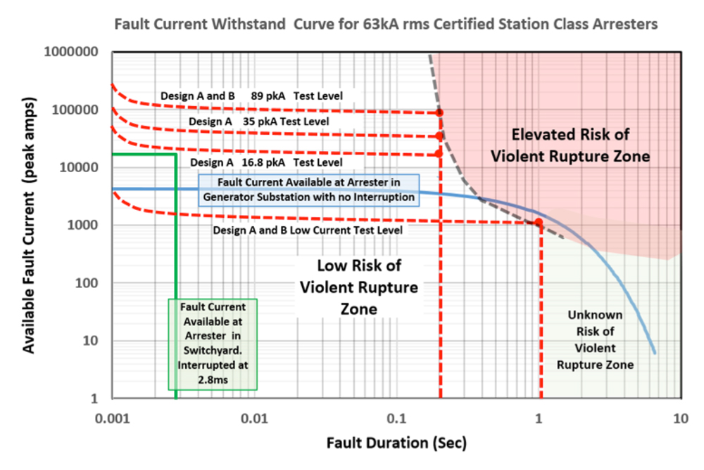
To help understand how to apply fault current test results, an Arrester Fault Current Withstand Curve shows the currents at which arresters are tested in the standards. The chart is divided into three zones – Elevated Risk of Violent Rupture, Low Risk of Violent Rupture and Unknown – that describe what might happen if an arrester is subjected to these fault current amplitudes and durations. End of life performance with respect to fault current can then be assessed by plotting expected fault current at the arrester’s location and analyzing the zones this passes through.

The plot shows the fault current experienced by two arresters – both certified to 63 kA short circuit capability – from two different circuits and compares how they react to fault current based on location. The green curve represents the fault current experienced by a switchyard arrester with 17,000 peak amps that is interrupted in .0028 seconds; the blue line represents the fault current an arrester at a generator substation might conduct during an end of life event. The current is not interrupted in this case but decays as the generator slows down.
For the switchyard arrester, it seems that the arrester should perform well and not rupture from the event. By contrast, the performance of the arrester at the generator station would be questionable and perhaps the supplier should be consulted since it passes into the zone of high rupture risk. As evident, what may seem a simple ‘yes’ or ‘no’ proposition can sometimes prove more complex.