Powerlink Queensland is a government owned network service provider that builds and operates the extensive transmission network in Queensland, Australia. Approximately 30,000 non-ceramic insulators (NCIs) are installed on this system that operates at 110 kV, 132 kV, 275 kV and 330 kV. This edited contribution to INMR by J.A. (Tony) Gillespie of Gillespie Power Consultancy and Glenn Stapleton, Principal Transmission Engineer at Powerlink, reviewed experience with NCIs over more than two decades and across the entire life cycle.


Electricity Environment
A high voltage AC network operated by the National Energy Market Operator interconnects the east coast of Australia and stretches some 4500 km from Cairns in North Queensland to Port Augusta in South Australia. About 1700 km of this network lies in coastal Queensland and is owned and operated by Powerlink. Installed circuit kilometers of all Powerlink transmission lines are:
• 700 km of 330 kV;
• 9800 km of 275 kV;
• 4400 km of 132 kV;
• 400 km of 110 kV.
Maximum demand in Queensland is just over 10,000 MW with little annual load growth but increasing reliance on renewable power sources. For example, about 1600 MW of renewable generation was either connected or under construction during 2017 & 2018. Financial penalties can be imposed by the Regulator should power flow become constrained, such as when lines have to be de-energized to replace insulators. Such constraints effectively raise market price for electricity. At present, a substantial share of Powerlink’s total population of NCIs is nearing the end of expected service life yet replacement will be difficult if lines have to be taken out of service in the process. Therefore, it is strategically important to be able to change NCIs live.
Background
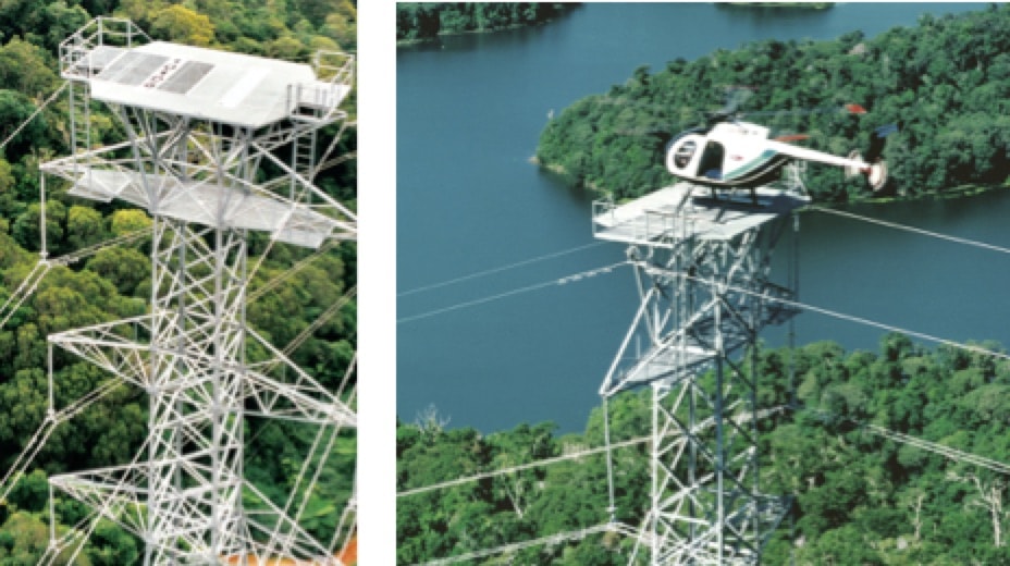
During the late 1970s and early 1980s, small populations of NCIs were installed in Queensland on a trial basis. Later, in 1992, approximately 1000 such units were installed on a new 275 kV transmission line passing through an environmentally sensitive rainforest.
CLICK TO ENLARGE
Pin corrosion has been the dominant failure mechanism for disc insulation on lines located close to the coast of northern Queensland. In extreme cases, service life has been less than 15 years. Fitting discs with zinc sleeves on pins has been successful in extending service life in such extreme environments exposed to onshore winds but by only about 20%, i.e. only 3 to 5 years. Given that NCIs experience lower leakage current than porcelain or glass, these were initially seen as a good alternative for such marine environments. Later, in 1997, Powerlink decided to adopt NCIs as standard insulation for all new projects and about 22,000 units were installed on lines built over the following five years. By 2002, however, insulator selection policy was again reviewed with particular regard to:
1. service life of NCIs not being fully known;
2. high susceptibility of NCIs to damage from bird pecking, first considered a threat before new lines are energized but later discovered to occur in high-risk areas at all times;
3. insufficient understanding on how best to diagnose condition of NCIs.
Standard design build therefore reverted back to glass and ceramic discs while NCIs were adopted only for specific applications. This strategy has continued to the present. Current application conditions that favour NCIs for new build or refurbishment projects include:
• assets situated near public areas for improved aesthetics;
• compact construction using insulated cross-arms;
• ‘like-for-like’ replacement as part of end-of-life refurbishments;
• areas with heavy to extreme pollution.

Impact of NCI Design Practices on End-of-Life
Insulator replacement typically makes up some 40% of transmission line maintenance budgets and the quality of new insulation must therefore assure high reliability. All of Powerlink’s insulation assemblies are designed to facilitate live maintenance.
Specification of NCIs
Prior to 1996, a range of early generation NCIs was installed in Queensland and this created logistical and maintenance problems. To facilitate and streamline like-for-like replacement, independent of supplier, and to reduce complexity in managing inventory of spares, specification of NCI long rods has become increasingly standardized to include:
• standard mechanical rating of 160 kN;
• standardization to IEC ball-eye end fittings for all applications, including suspension, strain and horizontal vee;
• one coupling length per voltage level with tolerance of ±75 mm for long rods and ± 25 mm for posts;
• two different creepage lengths, i.e. 23 mm/kV phase-to- phase for light and medium pollution and 31 mm/kV for heavy or very heavy pollution.
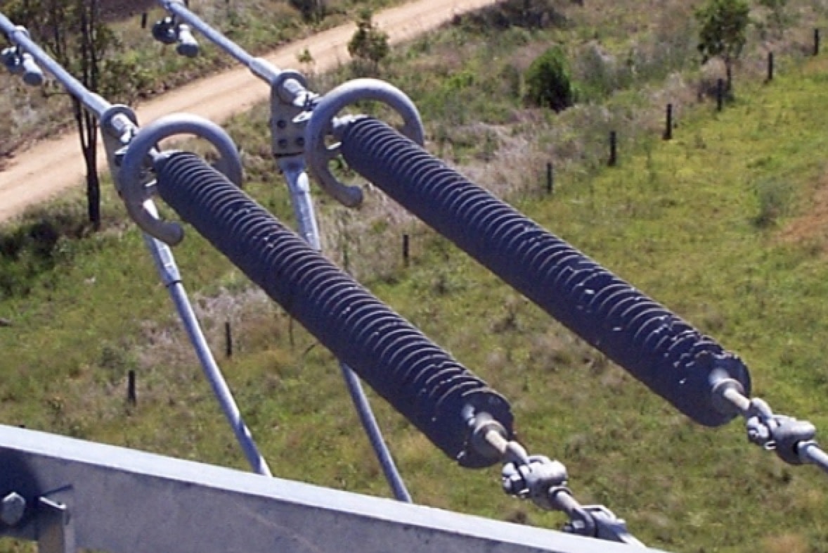
Powerlink requires all NCIs (both long rods and posts) be equipped with corona rings at 110 kV and above. NCIs are specified as silicone rubber with minimum sheath thickness of 3 mm. Bridging posts are used in strain positions to reduce jumper swing toward structures under high wind. A 63 mm diameter core rod has been found sufficient in the case of relatively light cantilever loading, e.g. up to twin conductor horizontal or vertical bundles, yielding a low weight post that is easy to handle live. Where possible, bridging posts are standardized and selected with shorter arcing distance than strain long rods to ensure flashover occurs across the post rather than across the more critical strain insulator. A universal post is used for line post and horizontal vee applications with associated increase in core diameter up to 88 mm. Different fabricated fittings are bolted to the ends of standardized flanges on universal posts to produce different types of assemblies. Both pivoting and fixed twin post, horizontal vees have been installed.
Powerlink Queensland has several lines up to 330 km in distance, operating at 275 kV and 330 kV. These long lines are subject to summer storms with high lightning activity and ground flash density in some parts of the network can be up to 4 strikes/km2/yr. All faults are investigated and, if any flashed insulators are discovered, the entire string is replaced. Arcing horns are not fitted to NCIs or disc insulator strings since these reduce arcing distance as well as lightning performance. Third generation NCIs on Powerlink’s network have displayed high reliability and there have so far been only rare, isolated failures. The conclusion is that the above design practices, combined with emphasis on standardization of dimensions and ratings, has resulted in performance that has met expectations during initial project design.

Impact of Construction Practices on End-of-Life
Construction Supervision & Quality Assurance
The high penetration of NCIs being installed over a relatively short time frame resulted in line contractors being exposed to a step change in insulator technology. This impacted construction methods and some initial problems attributed to contractor unfamiliarity with these insulators occurred during transport and handling as well as rigging and lifting NCIs onto towers, especially longer units for higher voltages. For example, torsional loading during termination of conductors into strain assemblies needed to be better considered. Similarly, it was necessary to ensure that lines workers did not walk on insulators to access conductors. To deal with these types of issues, a team of experienced inspectors worked alongside construction contractors to ensure everything was being performed in accordance with specifications. Moreover, regular training sessions were offered to inspectors on each project, covering usual topics as well as refreshers on NCI design, handling and precautions when erecting line materials. Indeed, the consistent reliable performance of Powerlink’s population of third generation NCIs can be largely attributed to the role that quality inspection and site supervision played during construction.
Bird Damage
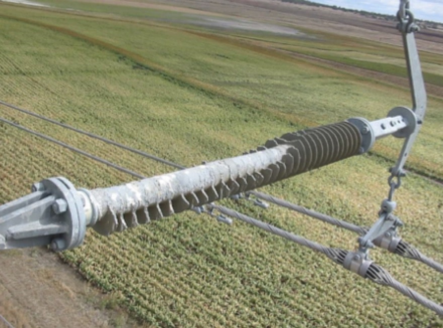
Bird damage to NCIs has been well documented, starting with construction projects dating back to 1998. Such damage was observed on most types of NCIs, including post insulators and long rods, but did not necessarily always occur during construction. Most affected insulators were long rods although a small quantity of bridging posts on tension structures were also affected. In the case of vertical suspension insulators, bird damage is almost exclusively at the tower end and at the live end adjacent to the corona ring. By contrast, horizontal tension strings have typically suffered shed and sheath damage all along the insulator, with greatest concern being those cases where the fibreglass core has become exposed. Unfortunately, sheath damage to suspension insulators adjacent to the corona ring is difficult to identify from helicopters or during ground-based inspection. Moreover, what caused significant alarm was the speed at which bird-chewing damage was recorded following erection of insulators. Ground surveys revealed that this problem was caused mostly by galahs and to a lesser extent by sulphur crested cockatoos – both species having sharp hooked beaks. These birds are prevalent mainly in areas where water is available, such as near creeks or dams, and also close to fields of growing grain. Nesting sites in trees close to a transmission line are considered a factor that increases local bird population.
CLICK TO ENLARGE
Various bird surveys and related risk assessments were performed at the time to assess suitability of NCIs on new transmission line assets. However, as highlighted by Fig. 1, deployment of large numbers of NCIs reduced significantly starting 2001. Although failure modes specifically attributed to bird damage during construction have not yet been encountered, the issue of bird pecking remained a concern. This was because it was difficult to detect such damage during aerial patrols aimed at identifying and replacing damaged units prior to energization. A particular concern was potential damage to the high electric field region of an NCI but that could be hidden from view by the corona ring.
CLICK TO ENLARGE
Observations During Operation & Maintenance Phases Installation of NCIs
Bird Damage to Energized NCIs
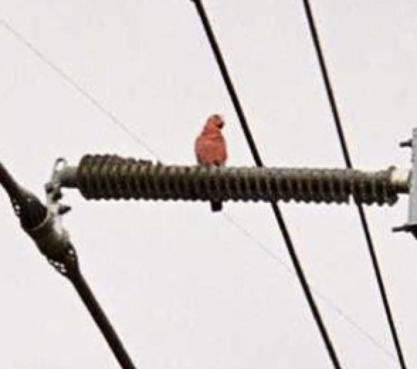
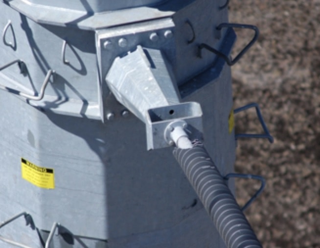
In early 2005, it was confirmed that birds were chewing live insulators on 110 kV and 330 kV lines on Darling Downs. For example, significant damage occurred to horizontal vee posts at 330 kV and 110 kV as well as to 110 kV line posts due to their favourable orientation in terms of accommodating bird perching. Damage was mainly in localized sections of these lines rather than on every structure and most extreme cases were observed on insulators installed near sources of food and water.
CLICK TO ENLARGE
Birds appear to favour a horizontal perch for chewing and have also damaged the dead ends of 330 kV horizontal line posts. By contrast, such damage has not been observed on the inclined long rods in horizontal vee assemblies.
Bird behaviour seems to have changed, with increased incidence of chewing damage to live insulators localized mostly in certain areas. As a result, Powerlink has become reluctant to install large numbers of NCIs on its transmission network until a solution to the problem has been identified. In this regard, porcelain posts have been investigated as replacement for chewed horizontal vee and line posts. Indeed, prototype replacements were installed and considered for new lines but ultimately rejected due to weight, poor aesthetics and risk of brittle failure under impact loading (e.g. from trees falling onto lines). Instead, external outer-rib style porcelain discs were installed on a western line for connection to a coal-fired power station. Previously, such an environment would have favoured selection of NCIs due to their superior contamination performance.

It has been found that aluminium sulphate dissolved in water and sprayed onto a structure and to the ends of NCIs deters birds from chewing but this solution did not prove economical given the need re-spray following rain. Field trials of various audible and ultrasonic devices to deter birds were also carried out and, while these do keep birds away, this approach is only able to protect a single structure. Modelling electric field of chewed NCI assemblies was undertaken as well to determine maximum comfortable field perception values for perched birds.
CLICK TO ENLARGE
CLICK TO ENLARGE
The bird-chewing problem has changed over time and is now thought to correlate with seasonal variations of climate. In particular, parrots have migrated closer to the coast during relatively dry years, bringing them near those assets where NCIs are typically installed. Nonetheless, bird chewing of live NCIs has reduced in frequency over recent years and there is now only occasional pecking damage being reported in maintenance notifications.
Mid-Life Service Experience
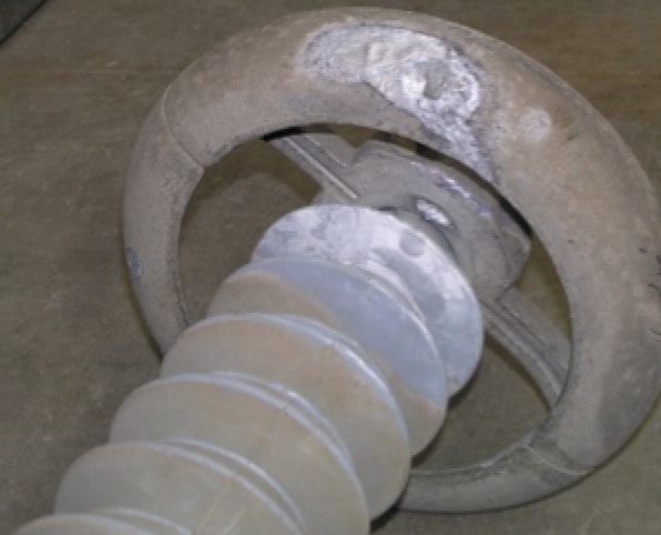
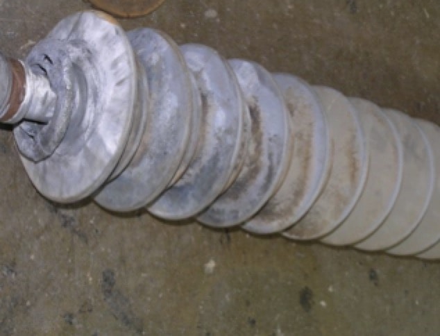
In October 2008, a lightning strike to a 275 kV line 1 km from Tarong Power Station caused a power follow earth fault current of 29 kA that was cleared in 120 milliseconds. The affected flashed NCI was retrieved and following damage was noted:
• arc damage to the corona rings and metal end fittings;
• rust on top metal fitting;
• whitening of sheds due to heat removal of silicone, leaving the aluminium trihydrate filler visible.
While none of this is considered serious and the insulator could well have remained in service, whenever such damage is noted during feeder patrols to identify fault locations, such NCI units are scheduled for eventual replacement with low to medium priority. The primary long-term concern for NCIs with arc damage is risk of corrosion inception on end fittings due to loss of galvanization during the flashover.
CLICK TO ENLARGE
CLICK TO ENLARGE
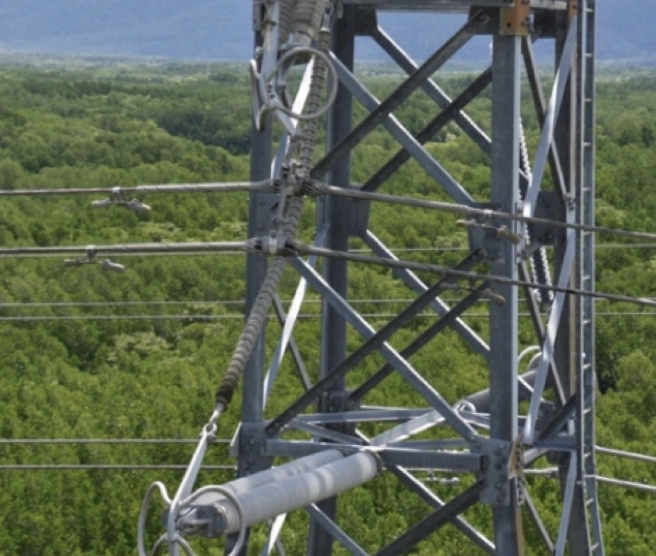
Moreover, apart from these situations, a small number of other types of failures have been recorded with third generation NCIs in service on Powerlink’s network. Predominant failure modes have included:
• mechanical failures during adverse weather due to dynamic loading from insulator cross-arm flip-over events affecting horizontal-vees;
• mechanical failures due to brittle fracture of the fiberglass rod resulting from inadvertently omitted or improperly positioned corona grading devices at 275 kV and above;
• isolated incidents where corona rings have inadvertently been left off the live end, causing blackening of nearby sheds.
CLICK TO ENLARGE
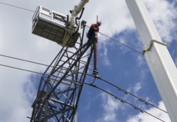
Live Working Considerations
All live work on the Queensland transmission system is well controlled. Methods are developed and practiced dead and, only when proven safe and effective, are prescribed in operating procedures. Visual inspection continues to be the primary method for assessing the condition of NCIs prior to any particular live working task. This represents a different mindset to condition and risk assessment of disc insulation and lines workers must therefore be suitably trained.
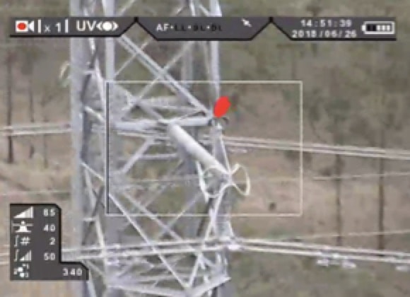
Different visual and risk assessment tools have been tried at different times over the service life of 3rd generation NCI units. These have included the prototype EPRI live working NCI tester as well as equipment to measure electric field profile along in service units. Even with advancement and evolution of these technologies, risk assessment is still based mainly on visual assessment by trained live line and bare hand workers. Energized insulators are examined visually to check for shed, sheath and end fitting damage. Seals at the triple point, where sheath, rod and end fitting meet, are checked for damage and for rust that may indicate moisture has penetrated within. Insulation defects are classified based on EPRI’s Insulator Visual Inspection Guide. Only insulators having defects with certain classifications can be changed live. Should assessment identify some uncertainty in ranking risk on insulator condition, more advanced site-specific techniques are adopted to better quantify risk. These include thermal scans to check for hot spots as an indicator of heating from excessive leakage current or use of a corona camera to identify possible partial discharge issues.
Population Assessment for Estimating End-of-Life & Prioritizing Replacement
As of 2019, all early generation, prototype and trial NCIs have been removed from service such that only third generation NCIs remain on Powerlink’s network. There are three predominant suppliers for this remaining population, of which a significant proportion are now approaching 20 years of service.
Fleet Strategy
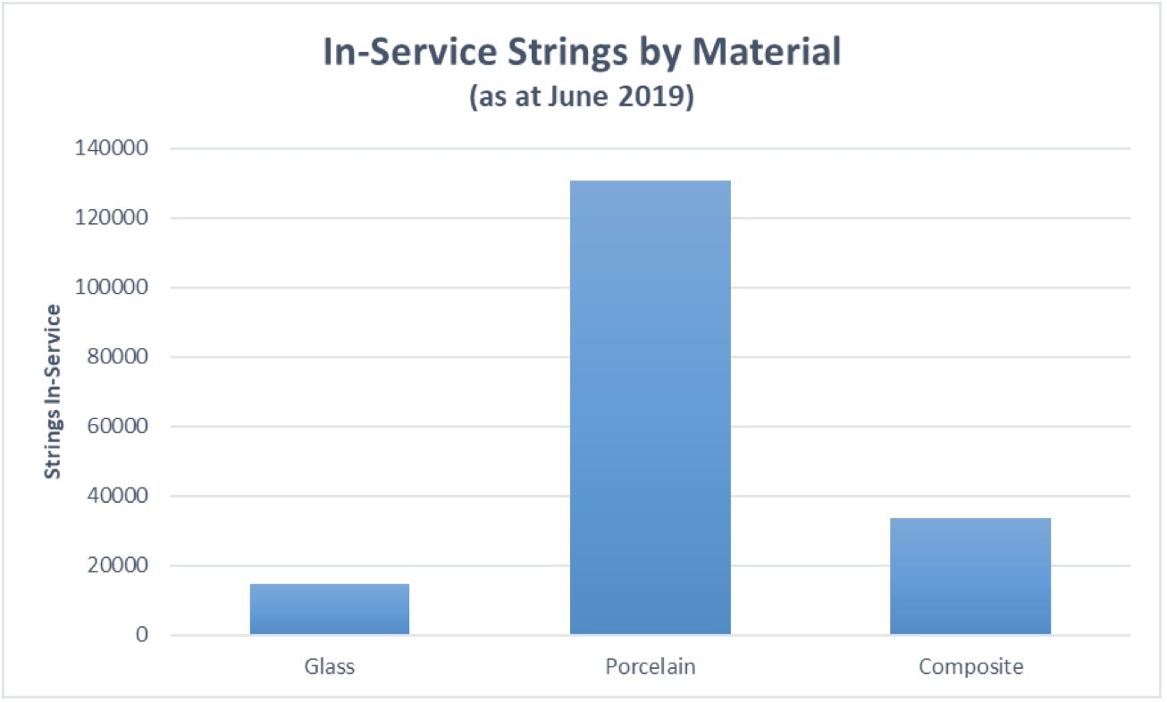
Fig. 2 provides a comparison of the relative proportions of different insulator types in the Powerlink fleet. In the case of NCIs, 99% of this population are made from silicone rubber with only a small number of EPDM and ESP materials still in service. The majority of this NCI population entered service within a compressed time frame between the late 1990s to mid 2000s. This population has displayed high reliability and there have been only rare, isolated instances of failures.
CLICK TO ENLARGE
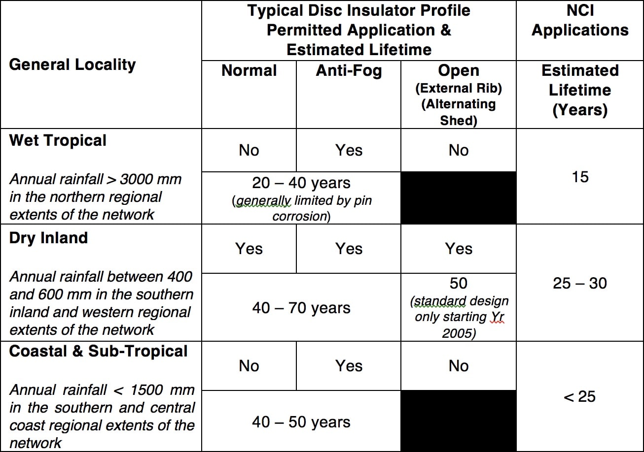
Environmental conditions vary across the network and specific regions are classified broadly in terms of average annual rainfall (most applicable for NCIs) or exposure to corrosion (most applicable to ceramic and glass insulators). Annual average rainfall is considered as correlating directly to corona performance and lifetime expectations for NCIs. This is due to the numbers of hours insulators remain wetted and associated possible degradation from water drop corona. Table 1 summarizes Powerlink’s regional classifications and typical service life expectations for application of both disc insulators and NCIs. A fleet management approach for the NCI population uses primarily condition assessment data from scheduled climbing inspections as well as helicopter patrols. This information becomes the primary input into an iterative derivation of a Health Index for any particular asset. Information from routine inspections can also assist in predicting whether degradation of any particular NCIs is progressing in-line with expectations from Table 1 or at an accelerated rate due to other site-specific factors such as bird chewing damage, microclimates, pollution sources, etc.
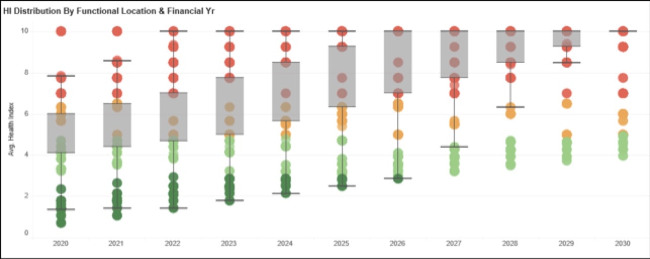
Fig. 3 highlights a typical Health Index representation for one particular sub-population of NCIs, showing the extrapolated trend for Health Index over time. These can be expressed as a box and whisker plot to represent the measure of spread for the particular population of interest. Business intelligence software tools are then used to visualize asset data repositories and provide a valuable means to better understand population performance for the time period of interest. Projecting health indices into the future assists better defining inspection protocols as well as prioritizing timing for replacement if necessary.
Periodic assessment of the condition of NCIs mainly takes the form of visual assessment, especially during the first half of their projected service life. Structures equipped with NCIs are patrolled predominantly by helicopter, supplemented by less frequent climbing and ground-based inspection. Climbing and aerial patrols are tasked with identifying visual indicators of condition including:
• shed and sheath cracking, with particular focus on the area close to the corona ring or in the high E-field region if there is no corona ring;
• darkening of rubber in the high E-field region;
• chalking and whitening;
• corrosion of end fittings, especially close to the metal/rubber interface;
• loss of rubber or erosion of housing material, with targeted focus near end fittings;
• qualitative assessment of integrity of seal interface between metal end fittings and rubber.
CLICK TO ENLARGE
As its NCI population has continued to age past anticipated half-life and towards end-of-life, Powerlink has employed a number of additional sampling and inspection measures to complement visual inspection data and help refine estimates for remaining service life. Such approaches are warranted to better prioritize and plan for replacement given finite labour resources to undertake the work as well as budget constraints linked to regulated operational expenses for transmission utilities in Australia. Such prioritization for replacement and fleet management has used predictive approaches to assess and rank the combined effects of:
• severity of installation location and environmental stresses (area classification as in Table 1);
• electrical and mechanical stresses in-service;
• predicted performance by supplier and material formulation, with the development of time to degradation and time to failure models on a per-supplier basis;
• development of health indices by supplier, taking the sensitivity of the above factors into account.
Replacement sequence and prioritization determined this way aims to implement replacement of all NCIs just in time and before progression of degradation (with sufficient safety margin) would reach the point that would no longer permit undertaking replacement live. Such an approach results in some sub-populations being removed from service before condition-based assessments would normally conclude that these have reached end-of-life.
CLICK TO ENLARGE
Population Assessment Phase 1: Onset of Degradation & Predicting End-of-Life
Powerlink has used detailed input both from EPRI for NCI insulator research delivered by Overhead Transmission Target 35 and from CIGRE publications by Working Group B2. For example, EPRI condition assessment tools, ageing chamber performance data, electric field calculation software and population assessment software tools have all supplemented Powerlink’s own observations from testing and inspection data. Combining these inputs, Powerlink was able to develop a specific population and NCI supplier assessment framework and methodology to identify:
• likely degradation modes by supplier, also looking at the year the NCIs entered service;
• types of failure modes associated with a range of degradation conditions observed during periodic inspection;
• typical times to onset of degradation, based on applicable environmental conditions, regional classification, corrosion region and design electrical and mechanical stresses;
• projected time between onset of degradation and in-service failure, to enable suitable timing and prioritization of NCI replacement projects.
The Phase 1 desktop study also enabled a sensitivity study to be undertaken to better understand influence on degradation onset and time to failure from such factors as:
• impact of increased or decreased creepage distance on all NCI types in the fleet;
• omission or incorrect installation of corona rings;
• variation in electric field stresses on end fittings, rod and sheath, based on particular installation configuration;
• variations in isokeraunic levels for different line locations;
• increased or decreased electromechanical loads in-service for various applications and configurations;
• contamination hot spots and local microclimates, e.g. by comparing ratio between estimated pollution deposition level and NCI design pollution level.
CLICK TO ENLARGE
Population Assessment Phase 2: Model Enhancement & Calibration by Sampling & EHV Laboratory Testing
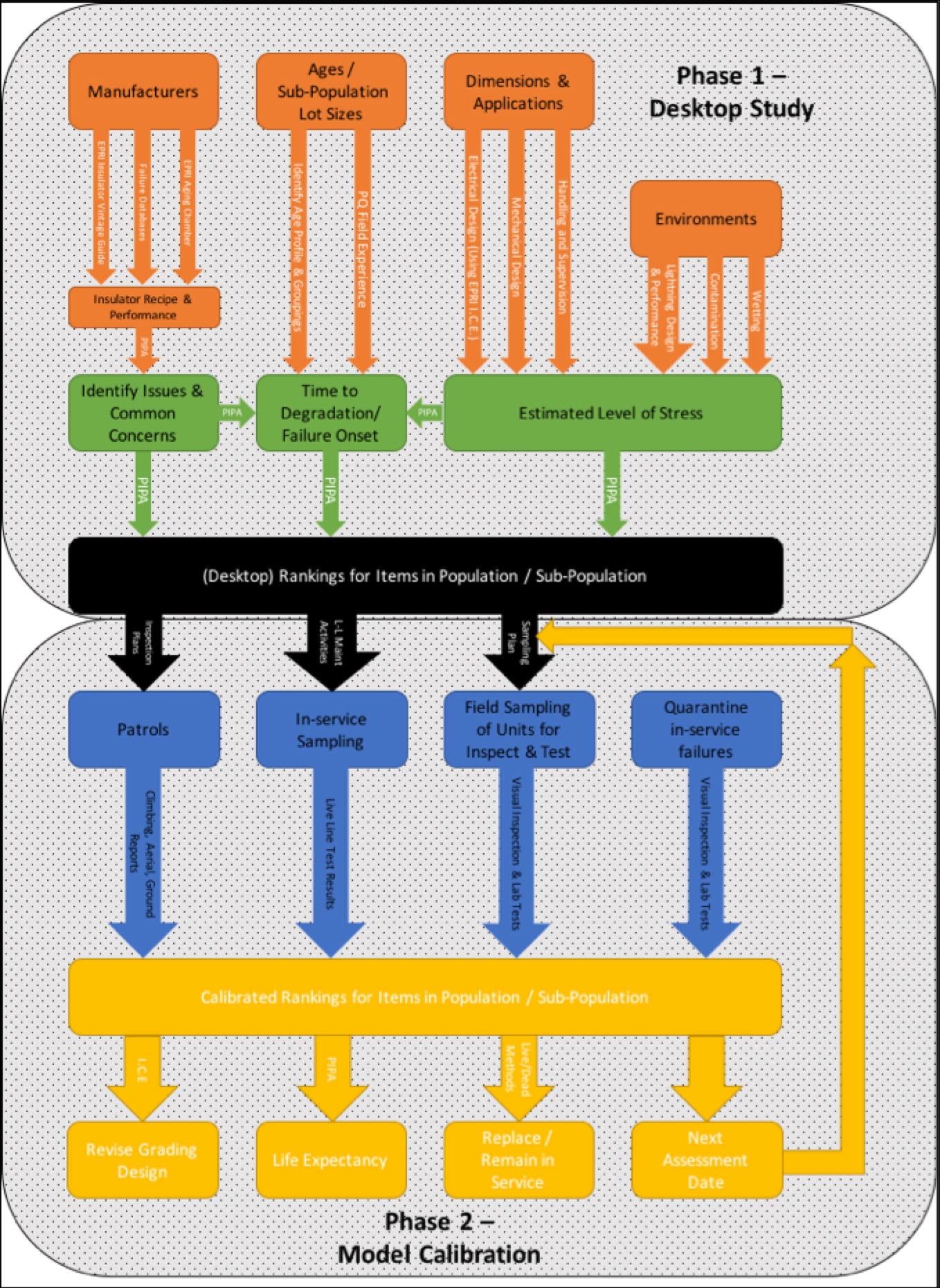
For each insulator sub-population, the Phase 1 desktop study provided an indication of relative probability of failure, associated timing for onset of potential degradation modes and corresponding time to failure following onset of such degradation. This offered a nominal time window to dictate ideal timing for replacement once initial degradation conditions are noted. Actual stresses, such as degree of surface contamination (leakage current), pollution sources and time of wetting are all subjective assumptions in the desktop assessment – especially when allowing for the effects of micro versus macroclimatic conditions. Therefore, a structured inspection, sampling and testing regime is required to assess actual condition versus estimated condition. Fig. 5 summarizes the typical investigation framework that combines Phase 1 and Phase 2 to allow ranking end-of-life and prioritizing need for replacement.
CLICK TO ENLARGE
CLICK TO ENLARGE
CLICK TO ENLARGE
A number of units were also removed from service for targeted EHV testing in a laboratory. Such testing also included a number of additional strings changed out in the past due to identified lightning flashover activity or minor cosmetic damage in order to maximize sample size.
Routine visual inspection performed in service as well as on recovered samples for laboratory testing did not flag heightened concern. These inspections focused primarily on integrity of the triple point seals versus time in service and compared results for all key NCI suppliers. Laboratory inspection and testing was then developed to focus on acceleration of potential failure modes internal to the samples recovered, based on the condition these seals displayed given their years in service. Tests were also scheduled to directly compare insulators recovered from the field to these same insulators that were kept in storage. These never used spares were of a similar age profile and manufacturing vintage but never energized. Performance testing in the laboratory therefore also aimed to compare ‘new’ units to units recovered from the field. Three primary types of laboratory tests were undertaken:
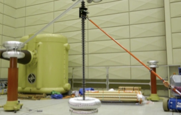
a. Power frequency test performed on complete insulator to measure resistive and capacitive components of leakage current:
These were carried out on each unit at maximum phase-to-earth system voltage. Tests were undertaken dry to simplify set-up and to assist in interpretation and repeatability of results. These were non-destructive and done at the start of the test sequence and as a follow-up check following the more destructive tests considered below. Such testing was used to provide a qualitative comparison of units by voltage and supplier, noting variation between new units and field-aged units. Pass/fail criteria of this test were subjective;
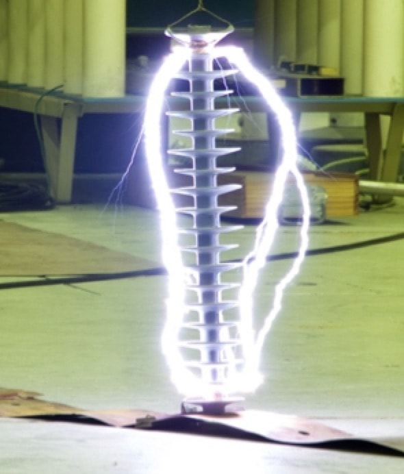
b. Steep front impulse tests on complete insulator units but performed sequentially along discrete 500 mm sections, given limitations in impulse voltage test set capability:
This test, performed in accordance with AS 62217 and with steepness of at least 1000 kV/µs, was mainly to assess internal condition of the insulator. It focused on adherence of sheath to rod and whether testing could lead to internal voids within this interface and resulting flashunder. Tests were conducted on both ‘new’ and recovered insulators.
c. Steep front impulse tests on cut and pre-conditioned units:
This test also involved steep fronted tests on units but applied this instead to cut 500 mm sections of NCIs that had been pre-conditioned by boiling in salt water in accordance with the CIGRE approach. The severity of this test was again looking to promote flashunder by artificially ageing the sample compared to the unconditioned tests described in b
d. E-Field Profiling:
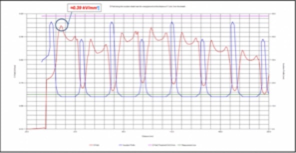
During energization of test samples in part a, described above, voltage profile was taken along each insulator. Profiles were also taken before and after steep fronted impulse tests in part b, but only on complete and intact samples.
CLICK TO ENLARGE
CLICK TO ENLARGE
EDITOR’S NOTE: Part 2 of this Article will appear in next week’s INMR WEEKLY TECHNICAL REVIEW and offer a case history of how Powerlink has applied its NCI condition monitoring and replacement prioritization strategy. It will also offer the Key Conclusions arising from two decades of experience with composite insulators on its transmission system.


