Test stations have been acknowledged as an important tool for evaluating insulator performance under different service environments. Typically, these stations are sited in areas having severe pollution problems and therefore allow accelerated accumulation of contamination.
As explained in this past contribution to INMR by industry expert, Dr. Frank Schmuck, test stations have allowed the behaviour of an insulator’s geometry and applied specific voltage stress to be investigated within a reasonably short timeframe.
With growing worldwide application of composite insulator technology on distribution and transmission networks, the usual two test parameters – ‘insulator geometry’ and ‘specific voltage stress’ have been supplemented by the additional aspect of ‘material performance’. Whereas creepage distance and shed profile have been the most important factors for glass and porcelain insulators, outdoor test stations allow investigating complex possible different ageing mechanisms that might affect composite insulators.
Simultaneous to acceptance of composite insulators, the suitability of various laboratory methods to test them has also been extensively studied and indeed remains an ongoing process. Two chamber tests, i.e. the salt fog and the multi-stress stress test as well as a wheel test are agreed methodologies to predict ageing of the shed material for a given insulator design (IEC 62217). Scientific investigations in recent years have also focused on quantifying hydrophobicity resistance and transfer properties (i.e. recovery) of various polymeric materials. This work has been considered important to better understand how insulator materials can be optimized, for example with respect to fillers and surface structures in nano or close to nano size.

Laboratory Testing Versus Test Station
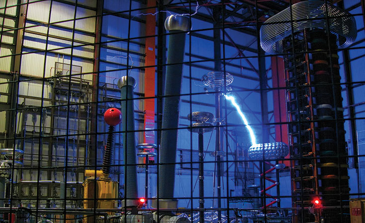
The many combinations of differing service parameters that can influence an insulator’s behaviour over its lifetime are difficult to simulate artificially and then to accelerate under laboratory conditions. For this reason the validity of laboratory test results is sometimes questioned. Users justifiably ask whether the procedures applied in the lab really take into consideration all the relevant factors that are encountered in service (e.g. intensity and duration of UV radiation, in-situ pollution deposition) while also perhaps over-emphasizing other factors. The situation becomes even more complex when taking into account the broad range of different polymeric materials as well as the industry trend toward cost reduction in manufacturing.
Much of this uncertainty can be compensated for by evaluating insulator performance at a naturally-polluted outdoor test station. Ideally, this should be done in combination with the requirement of passing all the ageing procedures described in relevant standards. Given the results of both – artificial laboratory testing and outdoor test stations – predicting insulator performance becomes that much more reliable.

Test Station Guide
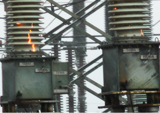
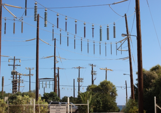
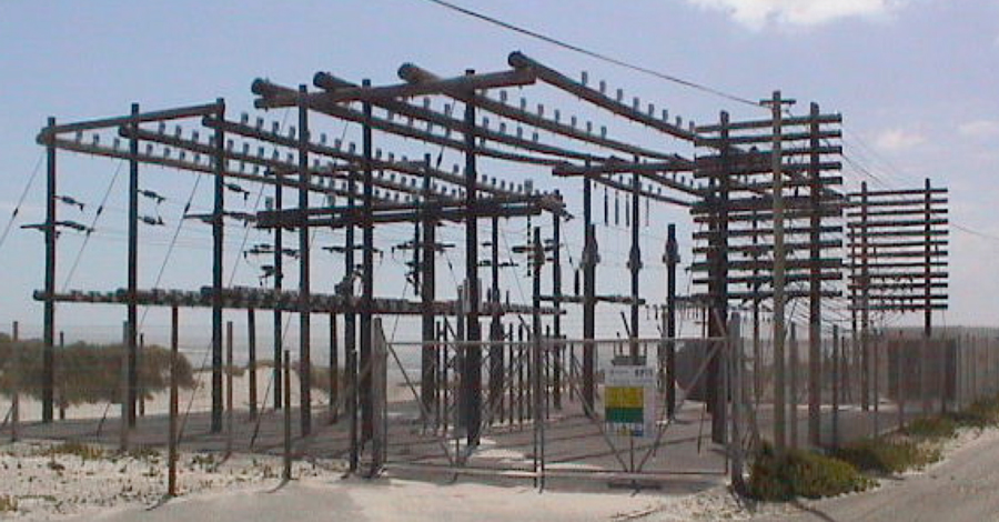
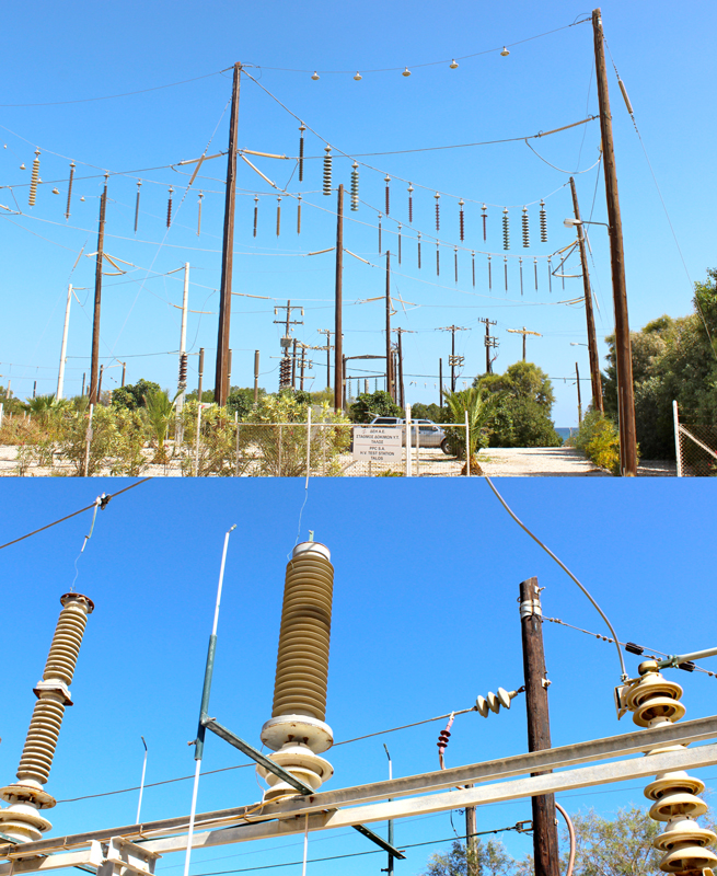
A former CIGRE WG prepared a paper: Guide for the Establishment of Naturally Polluted Insulator Testing Stations. This document, which can be used when constructing a test station to compare performance of alternative insulator designs, also provides recommendations for detailed inspection of specimens as well as for criteria to be looked at when selecting the most appropriate insulation for a particular application. This Guide was based in large part on practical experience with test stations in South Africa, in particular the now de-commissioned Koeberg facility first established in 1974 (see Fig. 1). Experience over years at this test station covered long rod, post and hollow core insulators (Fig. 3).
The Guide provides information from site selection for a test station to interpretation of results, including:
• Site Selection;
• Station Configuration;
• Power Supply;
• Test Specimen Arrangement;
• Measurements and Instrumentation;
• Insulator Inspection;
• Comparison of Results.
Photos and sketches enrich this document, providing for greater understanding of the topic. The photos in Ch. 8 of the Guide provide an overview of the variety of different insulator ageing modes, which allows it to also be used as a visual guide to help correctly interpret failure modes of any test specimens.
Required Input Data
Users of the Guide are asked to install a comprehensive data acquisition system consisting of:
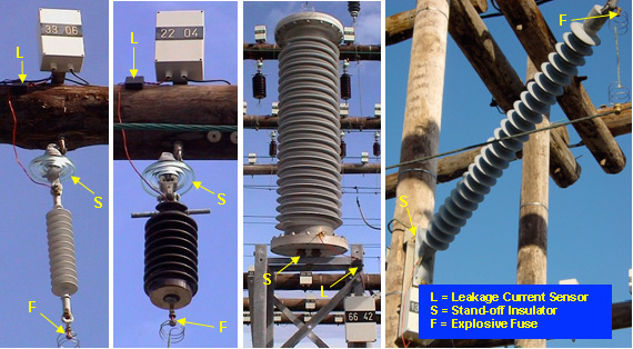
• leakage current activity;
• climatic (meteorological) conditions;
• pollution severity.
Due to possible flashovers of test specimens, data safety has to be guaranteed under such circumstances. Moreover, any partial discharge activity on one measurement channel should not be allowed to influence another channel. The availability of these data sets is an important precondition for correct interpretation of individual insulator test results. It has also been confirmed empirically that visual inspection and photo documentation during the test cycle help estimate risk of damage due to ageing, i.e. finding out whether there is progression or an end to any observed ageing.