A compendium of T&D images and their stories.
Lightning is a leading cause of transmission and distribution disruptions in many countries. In Mexico, for example, the Comisíon Federal de Electricidad has estimated that more than 50% of line failures have traditionally been linked to lightning. To reduce these outages, starting about 2000 CFE began a program of widespread application of line arresters. The externally gapped (EGLA) type was selected due to perceived advantages such as failures not adding to the system, pollution level not being a problem and no risk of disconnector device failure. Another important consideration was that EGLAs available in the local market were regarded as offering an excellent cost-benefit ratio along with less installation requirements.
Over the past 10-12 years, CFE’s 230 kV & 400 kV network has grown from about 47,000 km to almost 60,000 km while outage rate during this period decreased from 1.17 to 0.57 at 400 kV and from 1.27 to 0.59 at the lower transmission voltage. In the case of the 13 kV, 23 kV and 138 kV systems, which together grew during this period from about 369,000 km to more than 831,000 km, both gapless and EGLA type arresters are being utilized. However, the proportion of EGLA types has increased steadily due to difficulties in identifying gapless arrester failure from varistor block degradation or moisture ingress. Either could mean possible permanent failure on systems. More than 400,000 EGLAs have so far been installed on CFE’s T&D system from 13 kV to 400 kV, of which more than 85,000 were in service at 115 kV and almost 10,000 at 230 kV and 400 kV as of the end of 2017. Performance has shown this to be an economic as well as technical solution with not only improved reliability but also decreased outages and interruption time due to lightning.

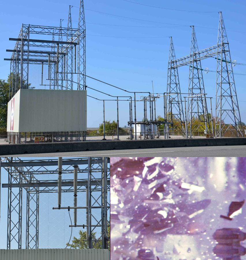
Self-supporting, fluid-filled terminations have been used since the advent of HV cables and continue to be the first choice among network operators due to excellent long-term performance. Recently, composite housings have begun to replace porcelain in such applications, especially when installations are sited near public areas. The basic design of these latest generation fluid-filled terminations consists of a hollow core composite housing and a silicone rubber stress cone installed onto the cable insulation. The remaining volume is usually filled with a silicone oil compound – one of the most environmentally friendly choice among alternative insulation media. The main advantages of this design are its ease of application across a range of different cable sizes and types as well as its adaptability to the service environment and mechanical requirements of any installation.
Although these types of terminations are reliable and safe, isolated cases of electrical breakdown can never be totally excluded. The worst-case failure mode results from a high temperature internal power arc that causes rapid vaporization and thermal expansion of the insulating medium. During a power arc inside a termination, the electrical discharge channel in the form of plasma leads to rapid transition of the insulating medium from liquid to vapor. The result is a sudden increase in pressure of the vapor phase, generating shock waves that stress the entire construction. If these dynamic stresses surpass the maximum mechanical strength of any of the termination’s components (i.e. its hollow insulator housing, top and bottom flanges or the bolts that fasten it to the support structure), mechanical breakdown can occur. Debris can then be ejected at high velocity all around the installation, threatening collateral damage to nearby network equipment while also presenting a threat to the public. Given this, cable accessory manufacturers have been trying to reduce these risks by minimizing possible consequences. The result has been development of explosion resistant terminations that provide a cost-effective as well as reliable solution in applications where terminations are sited in sensitive locations.
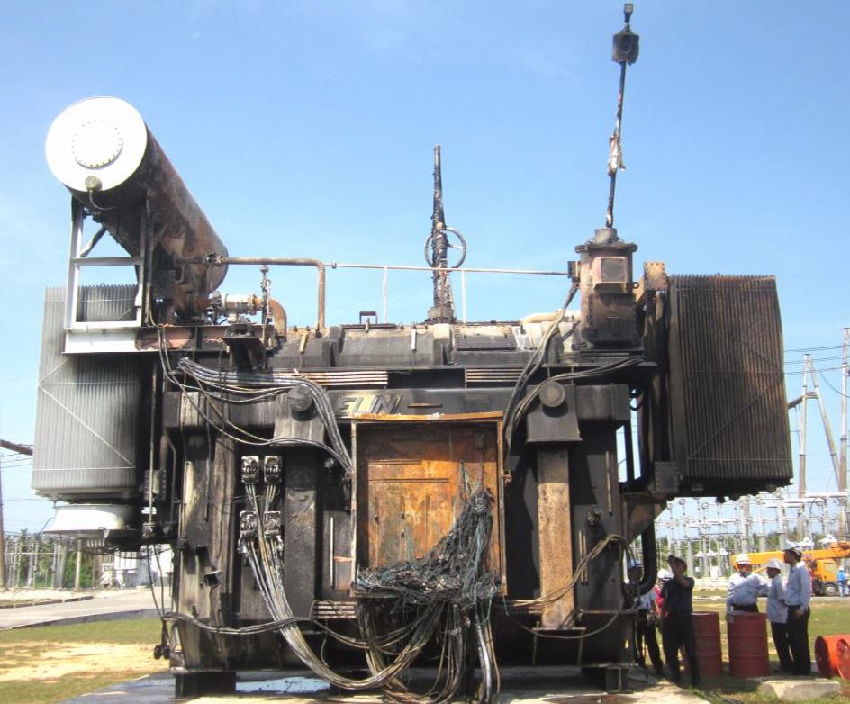
A high voltage bushing is a critical component in a power transformer and failure statistics confirm that bushings are among the three main contributors to transformer failure. Since bushing failures can have such huge impact on reliability and safety of a power system, major utilities in south-east Asia embarked on a bushing reliability survey with the goal of jointly formulating suitable mitigation measures to improve performance. That survey confirmed that, despite some variation in local strategies and techniques, the most common methods to assess condition of a bushing involved using dissipation factor, power factor and capacitance measurement. Test results were compared to nameplate values or previous tests and any increase or decrease from reference values were regarded as an indication of contamination and/or deterioration of the insulation system. Since limits for maximum permissible change tend to be manufacturer and type specific, interpretation limits in each case were usually based on statistical data from the entire bushing population.
While the basic design of an OIP bushing and a RIP bushing is the same, there are specific differences resulting in different ageing parameters. In the case of an OIP bushing, increase in power factor is a known ageing parameter. In addition, dissolved gas analysis might give further information about operational reliability. Any increase in capacitance, C1, indicates a partial breakdown, however the first partial breakdown might be followed directly by complete insulation breakdown and catastrophic failure. Therefore, C1 is not really an adequate ageing parameter. For an RIP bushing, partial breakdown is limited to its position without interaction with the remainder of the core. This is due to the fact that the condenser core is solid, in contrast to an OIP bushing where generated gases and contaminated oil can distribute to the entire condenser core. Since RIP bushings do not contain oil, no ageing of oil can occur and increase in power factor is not caused directly by ageing but rather by humidity ingress that weakens the insulation. This is usually not relevant for installed bushings, but might occur with improper storage conditions. With a drying procedure, humidity ingress into the condenser core can be removed. For both bushings, OIP and RIP bushing types, influence of stray capacitances should be taken into consideration if the measured values are compared with the routine test values. A fingerprint measurement taken after installation of the bushing in its final position is the best reference for any subsequent measurement.

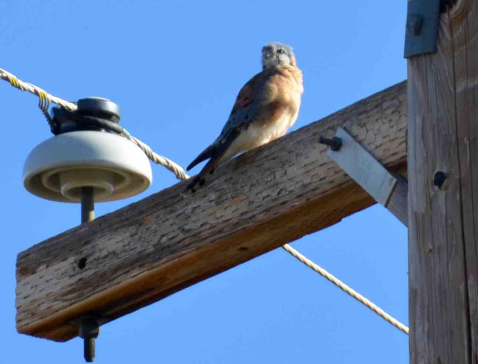
A large proportion of outages on overhead lines can somehow be linked to birds. But any discussion of such problems must distinguish the situation for distribution voltages from that in the case of transmission. The two are vastly different problems with entirely different solutions. In the case of distribution systems, the central problem is electrocution of birds and estimates of the numbers of birds killed each year are shocking. What makes the situation the more tragic is that the threat to birds has long been documented and there is adequate knowledge on how to solve or largely reduce the problem by insulating conductors close to the tower using protective devices of different shape and design. The principal requirement for such devices, usually made of polymeric materials, is that they have a service life similar to that of the components they are intended to protect, whether conductors, insulators, arresters. In this regard, they must be resistant to deterioration from weathering and UV. Experience with such devices has generally been positive and the only issue is the cost necessary to provide sufficient protection in areas known to have high concentrations of birds. Unlike the widespread carnage of birds along distribution lines, transmission networks face a much different challenge. Here, flashovers of suspension strings by streamer-type excretions are relatively common and can affect lines up to 500 kV. In these cases, birds fly away unharmed (though stressed by the flashover) while network equipment has to be relied on to quickly restore the line.
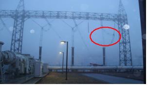
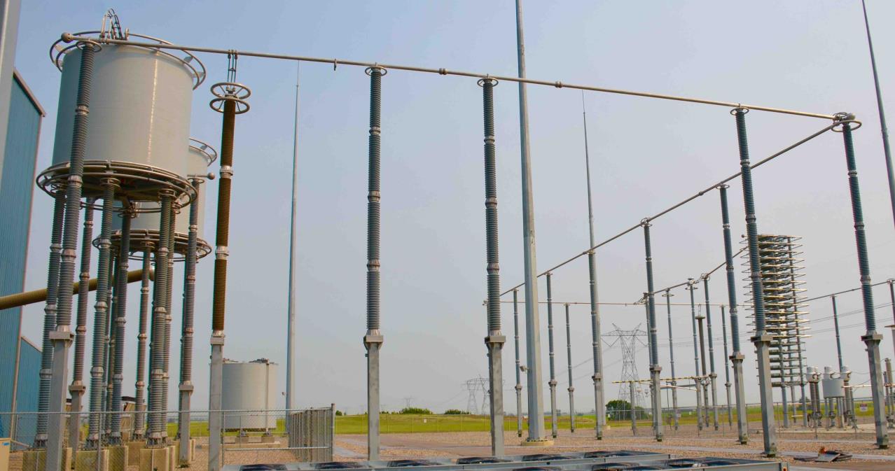
The advent of polymeric-housed station class surge arresters has opened up new possibilities in substation design since these can more easily be installed other than in the classical upright base-mounted position. Suspended mounting, for example, offers opportunities to reduce substation footprint and requires only minimal mechanical strength for the units. But substation construction in this case must be designed to support the additional weight of the arresters and this is often not the case for existing installations. Such mounting alternatives should therefore be considered early on in the planning process.
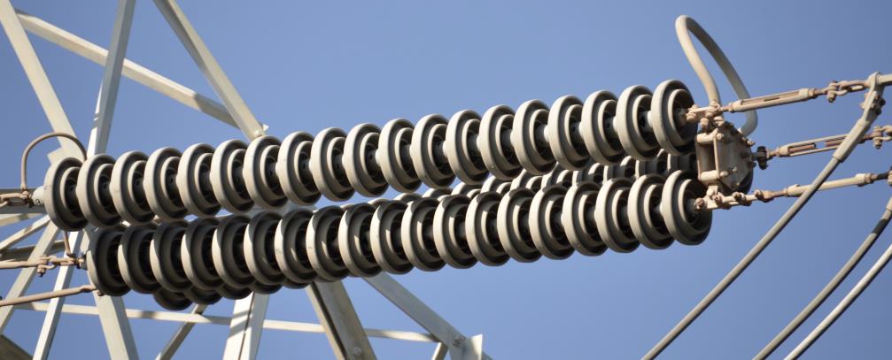
Among the notable trends in in recent years has been growing application of glass insulators pre-coated in the factory with an RTV silicone material. The goal is to combine the performance and maintenance benefits of toughened glass with the pollution performance of silicone. Service experience at Italian TSO, Terna – the world’s largest user of such insulators – has shown that failure rate of RTV-coated glass insulator strings is in line with that of uncoated insulators. If RTV-coated insulators do lose the enhanced performance offered by the coating, the string is only subject to de-rating, whereby it electrical performance becomes similar to that of the same uncoated string. Based on service experience in Italy, damage to a coating does not alter behavior of the string under contamination provided such damage is limited to only a few units. Moreover, there have never been reports of widely damaged strings, even after more than 10 years of operation.
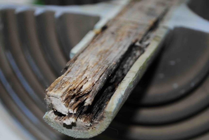
Wood pole framing is common on transmission networks across the globe. However, while the typical service life of such poles is normally between 50 and 60 years, damage caused by species of woodpeckers has, in extreme cases, required these to be replaced in only a fraction that time. Moreover, poles in affected line corridors may also need a more frequent inspection cycle since incidence of hole pecking occurs over a narrower time frame than most other problems. All this has made the activity of these birds a growing asset management problem. Moving to steel or concrete poles is an obvious solution but comes with the challenge of transporting and erecting much heavier structures, often at remote sites that are not easily accessible by road. Both materials also offer less BIL than wood and can impact an existing line’s electrical characteristics. A better option may be composite fiberglass poles that are light and offer lower installation costs than steel or concrete alternatives. Moreover, like wood framing, composite poles do not require special civil engineering to prepare foundations and are simply buried in place. Yet such structures are generally far more costly and not as easy to climb as wood poles and therefore may require bucket trucks for maintenance. Another question to be assessed by each power utility considering their use is how long a service life they offer under exposure to service conditions such as high UV and constant wetting as well as how easy they prove to be in terms of handling and drilling.
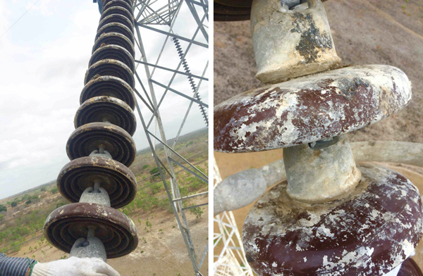
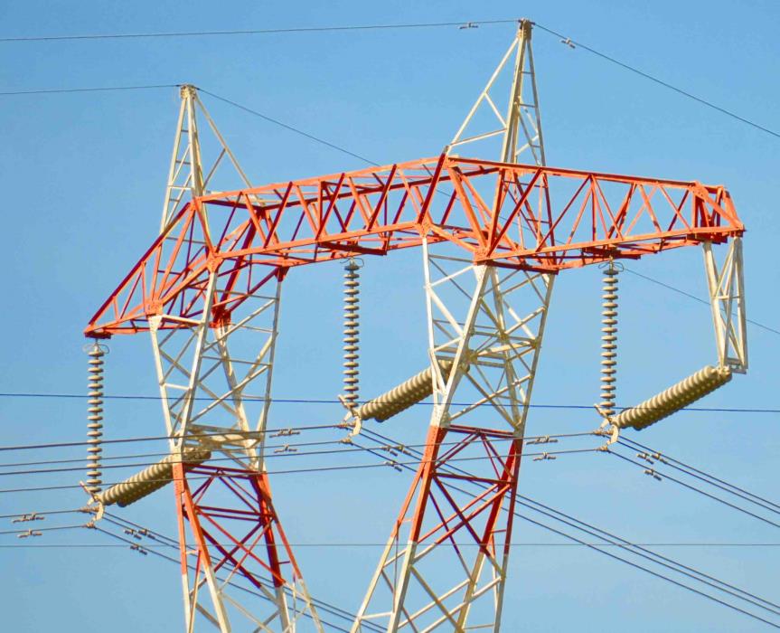
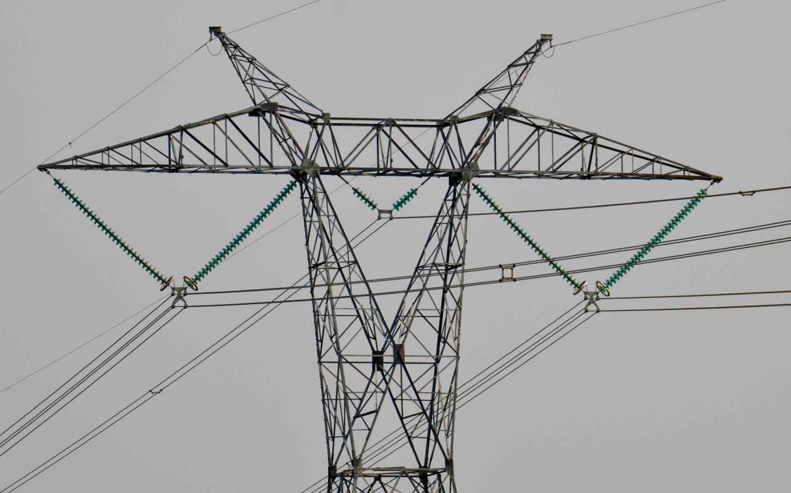
Pollution flashover takes place on an insulator string when bird guano builds up over a period of weeks or months during dry conditions with little to no rain to wash the surface. Birds favour certain places to perch and this is often at the extremity of a lattice tower arm directly above an insulator string. Over time, build-up of guano can be considerable but while conditions are hot and dry the relatively small individual amounts of liquid guano quickly dry and surface resistance level is not greatly altered. Flashover can occur when mist, fog or rain first returns and changes the dried guano into a semi-liquid state that greatly reduces surface resistance of the porcelain or glass. If the build-up of guano is sufficient and moisture is present to change conductivity of the whole insulator string, flashover will result.
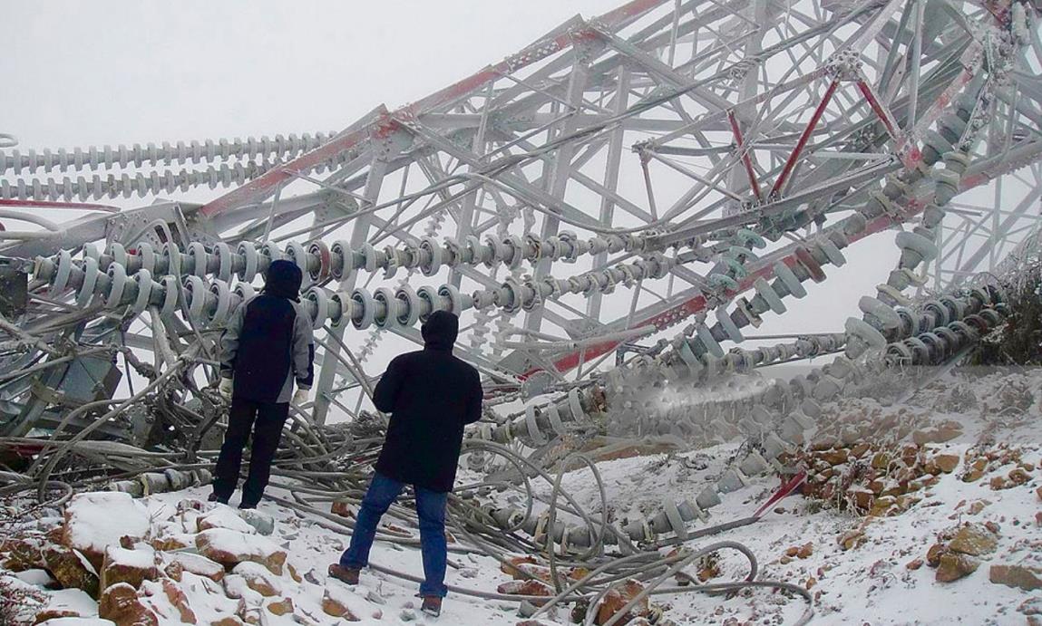
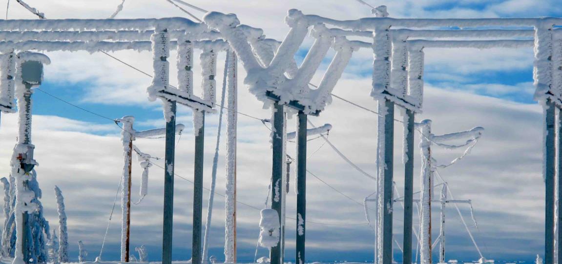
The impact of climate change is imposing new hazards for power infrastructure and among the threats that most affect overhead lines is wet snow – a type of snowfall characterized by snowflakes with high liquid water content that adhere easily to the surface of conductors and ground wires. This phenomenon develops under air temperatures in the range of 0°C to 2°C and a liquid water content greater than 30% of total snow mass. When precipitation rate exceeds 2 to 3 mm/h, an initial layer is deposited onto the conductor surface and constitutes the foundation over which a snow sleeve builds up. The phenomenon is often initially asymmetrical since snow accumulates more on the side exposed to wind. This shifts the centre of gravity and generates progressive conductor rotation around its axis. The rotation process is the root cause of the cylindrical shape of sleeves, whose densities can range from 150 to 500 kg/m3. When ambient temperature falls below 0°C, sleeves freeze and becomes highly compact. If snow accumulation generates mechanical loads exceeding the tensile strength of the conductor and causing mechanical strain, the combined effect under wind worsens the situation, either collapsing lattice towers or jeopardizing ground clearances. Moreover, abrupt detachment of a sleeve can result in violent rebound of conductors as well as ground wire, causing a permanent line trip. These types of events cannot be avoided but efforts can still be made to predict their occurrence in order to limit resulting contingencies and mitigate consequences.
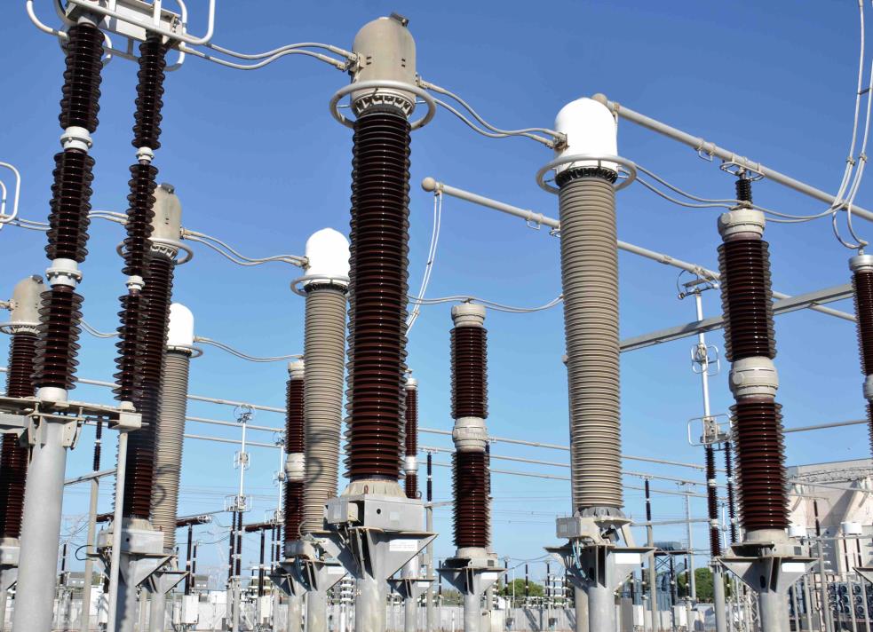
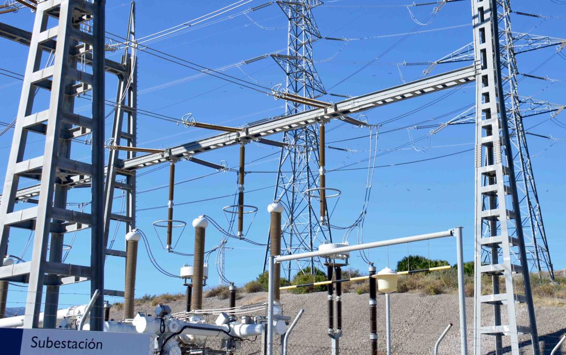
CTs and VTs in service at the connection of the valve hall with the AC substation at the Latina Converter Station in Italy demonstrate a fundamental change that has taken place among European utilities such as Terna when it comes to insulation philosophy. While the Italian TSO used to require only brown glaze porcelain insulators for such equipment, today, safety and security against risk of explosion from internal arcing have made composite housings mandatory for all new installations as well as whenever refurbishing or replacing old porcelain-housed units. In Italy, these composite hollow core insulators must pass specific tests such as a 2000-hour test and a recommended DC inclined plane test. The latter is necessary even for hollow core insulators intended for AC applications. Moreover, a specific maximum tangential electric field on the composite insulator surface is also required.
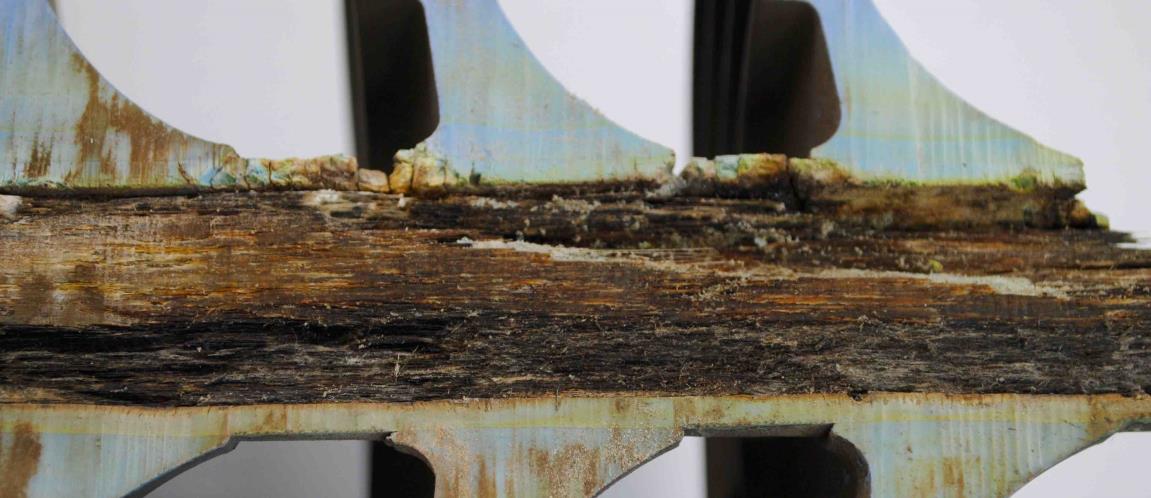
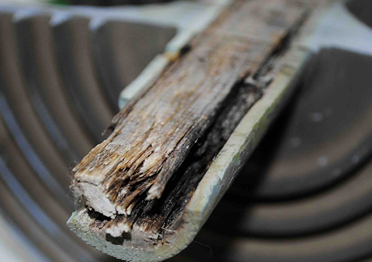
Unlike porcelain, composite insulators are not normally at risk of puncture since the electrodes of different potential are separated by a long fiberglass rod. However, punctures in the form of holes in the housing provide access for moisture to enter the core. Tracking along the rod under the housing material can then occur, resulting in permanent loss of electrical strength. If the internal tracking is considerable, the insulator will not be able to support the electrical stress and the rod will become carbonized along its length. This mode of failure, referred to as ‘flashunder’, can also result from damage to the polymeric housing from corona or from mishandling during transport and installation.
Here, the failed 225 kN insulator had been in service for about 7 years as part of a V-string in the 765 kV switchyard of a Korean power plant located in a highly contaminated coastal area. Investigation by the affected utility found that calculated E-field from the end fitting to 390 mm along the unit exceeded industry guidelines for composite type insulators. In particular, the highest calculated E-field value was 0.72 kV/mm at 165 mm from the end fitting and 0.45 kV/mm at the point of fracture. Corona from continuous wetting can cause excessive E-field on a polymeric housing and sharply accelerate ageing in contaminated environments. As such, control of corona activity is critical to prevent failures under these types of adverse service conditions. Full-scale testing of corona ring and end fitting design is therefore seen as essential ahead of both production and installation of such insulators.

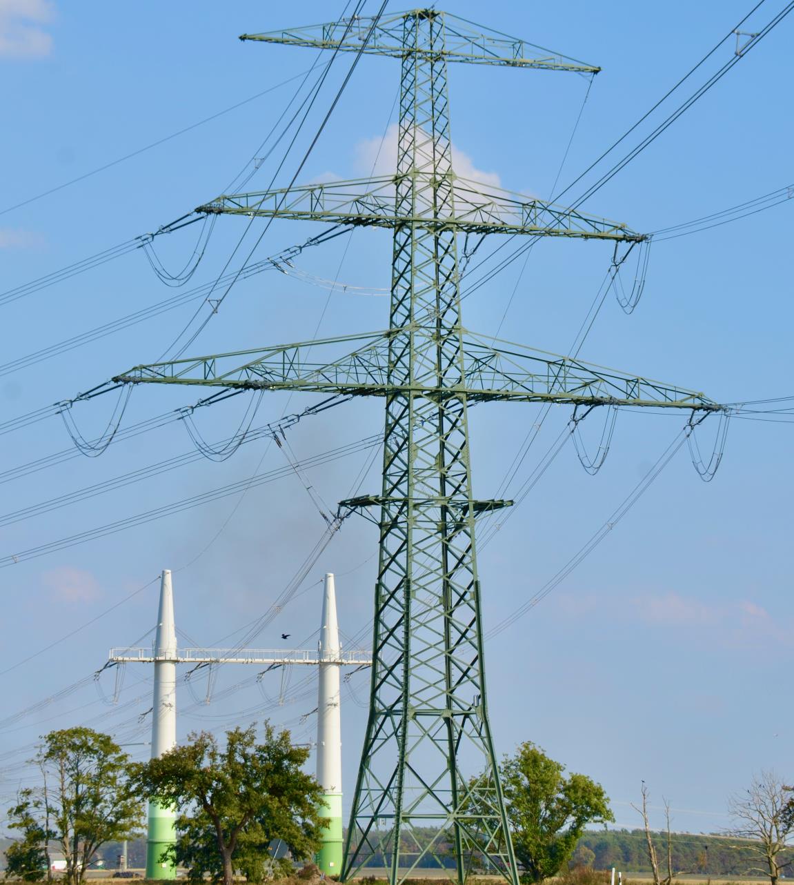
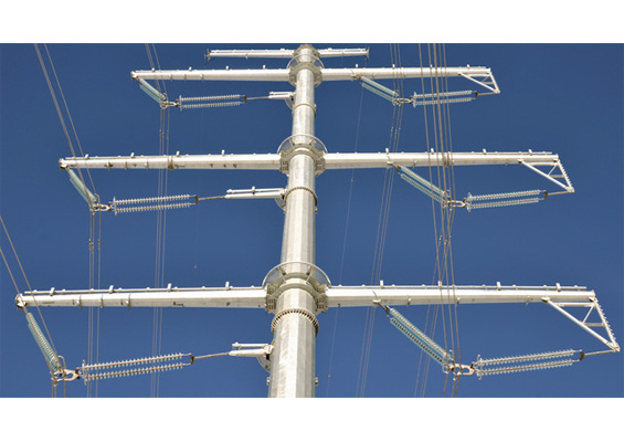
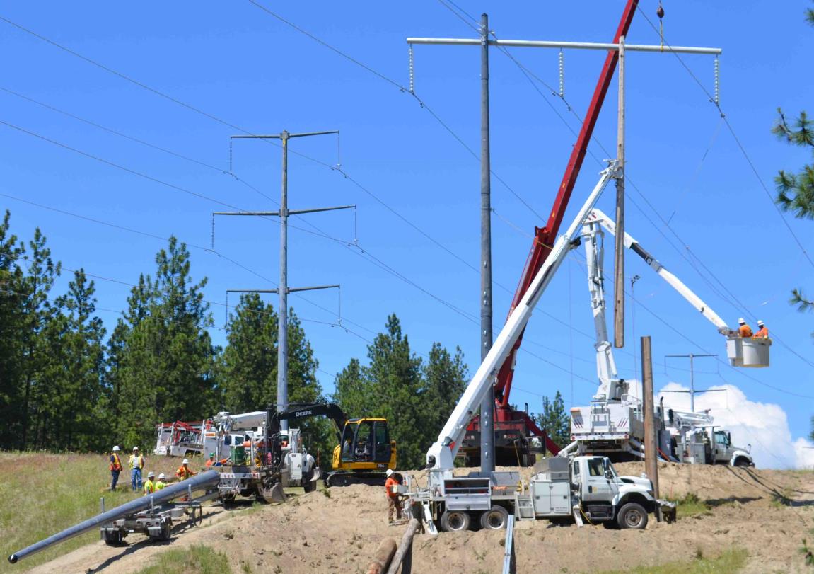
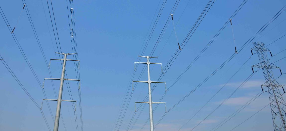
A survey conducted in Germany revealed that the dominant local objection to overhead line structures revolves around how much their height impairs local landscapes. As part of the effort to promote greater public acceptance of much needed new overhead lines, an entirely new approach was developed to limit tower height by significantly reducing normal conductor sag on typical spans. Here, at the connection point between a typical 400 kV tower design and the proposed new compact structure, the difference achieved in height reduction is abundantly evident.
Galloping problems in the Canadian Province of Alberta tend to be concentrated during the months of April and May when there is a critical combination of ice and high wind. A family of specially strengthened towers has been developed to better cope with such stresses and to improve their ability to handle icing up to a radius of 70 mm. Specifications for related line hardware have also been raised beyond typical ANSI requirements to 300 kN and even higher. Interphase spacers have also been installed. While these do not stop galloping, they prevent phases from clashing during galloping conditions and thereby reduce related outages. Galloping of 240 kV and 500 kV lines has also been dealt with by increased application of self-damping wires, which are lighter than conventional conductors and where the inner core is free to move inside the outer jacket. Tighter stringing and lower structures then become possible.
There are important differences between development of pollution flashovers under AC and DC energization. DC energized insulators typically accumulate more pollution than AC energized ones. Under low wind speed conditions, the electrostatic attraction of pollution particles under the unidirectional DC electric field overrules deposition by aerodynamic action. On AC energized insulation, there is little to no attraction of pollution by the alternating electric field. Field measurements indicate that the ratio of AC to DC pollution deposition can vary from 1 to as much as 10. With the absence of voltage zeros, dry band arcing under DC is more likely to grow into flashover than would be the case under AC, where dry band arcs need to re-ignite after each voltage zero. DC dry band arcs are also more mobile and more likely to leave the insulator surface to propagate through air. This necessitates development of special DC profiles to ensure effectiveness of the creepage distance. Another consequence of this difference in flashover development is the fact that the relative flashover strength of DC insulation deteriorates more than for AC insulation for any given increase in the pollution severity. Relative to other stresses, pollution performance is often the parameter that dictates the insulation design of HVDC systems. This is different from AC systems where insulation distances are typically determined by required lightning or switching performance of the line or substation. In polluted areas, extreme insulation lengths may be necessary in certain cases. This could force system planners to reconsider the whole conceptual design of a project to evaluate alternatives such as different line routes to avoid severely polluted areas or implementing cables or indoor switchyards to minimize the number of external insulation surfaces. There is thus a clear need to already consider insulation design for HVDC systems at an early stage in a project and certainly much earlier than customary for AC systems. It is also much more important to follow a detailed design process for DC systems because of the potential cost implications of either over-dimensioned or under-performing insulation.
Developments in improved station post insulator technologies are focused on minimizing arcing distances needed at busbars, disconnectors and similar apparatus, thereby contributing to more flexible substation design. Station posts can be optimized through better materials, decreased diameters, maximized mechanical strength and stiffness, less intermediate flanges and improved shed profiles as well as creepage factors. In the case of EHV and UHV applications, three station post alternatives are available: traditional and advanced porcelain solutions; composite insulator solutions; and hybrid insulator solutions. Most porcelain station posts continue to rely on relatively inexpensive stacking technology whereby posts having 1 to 2 m arcing distance are assembled to reach what is needed. This solution has greatest field experience, which confirms its reliability, especially from a mechanical standpoint. More advanced porcelain solutions now allow single post insulators up to several meters in height, thereby removing the need for intermediate flanges. Optimized profiles also offer reduced shed thickness and tip radius.
The composite insulator solution, having hydrophobicity transfer material (HTM) properties, also permits single post insulators of required length without flanges and offers additional advantages such as less weight and superior performance under pollution and seismic conditions. But these must be specifically designed to comply with all mechanical requirements, such as minimal deflection at the top in the case of disconnector applications. The hybrid solution, based on a porcelain core and a silicone housing, shares the advantages and disadvantages of the other solutions. One of the drawbacks of newer solutions is higher cost versus traditional stacked porcelain technology, where a competitive supply situation ensures pressure on prices. Pollution dominates design in the case of porcelain insulation, even when considering high creepage factors that are difficult to reach. Moreover, extreme heights could be necessary with such insulators, often making such a solution impractical or even impossible – especially for heavy pollution and high system voltage. More reasonable heights would be required for hybrid and composite insulator solutions, the latter being preferable in case of strict seismic requirements. Post type insulators with HTM properties are therefore the best solution for HVDC applications and their future development will depend on the pace of expansion of such systems worldwide.

Flashover problems across the globe confirm that ice and snow can significantly diminish insulator performance and impact grid reliability. Research published on this topic has confirmed that proper design of insulators for these types of service environments is critical and the deterministic approach reflected in IEEE 1783-2009 that forms the basis for most design might be overly conservative and lead to unnecessarily long insulators. The problem can best be looked at from a statistical viewpoint using an approach similar to that applied for contaminated conditions. Firstly, different environmental parameters need to be defined since these affect insulator performance. When characterizing ice and snow, the most important are: width (S), mass density (ρ) and equivalent water conductivity (σ in μS/cm, which also takes into account any presence of contamination). Each is characterized by a statistical distribution. It is also important to estimate how many critical events occur during a typical year (i.e. number of days with presence of ice and snow under conditions favoring flashover). Then, probabilistic insulator withstand characteristics have to be determined, usually expressed in terms of ISP (ice stress product) and SSP (snow stress product), that also take into account factors such as type of voltage stress (AC, DC+, DC-), insulator diameter, altitude, insulator inclination and number of insulators in parallel subject to this environment. Finally, acceptable number of flashovers per year has to be defined based on criticality of these various service phenomena as well as relative importance of the system under study. It is immediately clear that much data is needed. Often, such information is limited and provisional reasonable assumptions have to be made when trying to apply a statistical approach. More work may be needed to define ice and snow mapping (as already being done for pollution) and to determine insulator strength as a function of insulator inclination, for both ice and snow. Application of the statistical approach could help users better understand the importance of all different parameters and, once calibrated, could serve as an efficient tool when designing new lines.