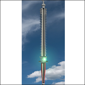
Magnetic torque couplings use magnetic field to transfer torque from one side (prime mover or driver) to another (load or follower). This technology is used in the power utility industry but also in sectors such as medical, automotive, aviation and research. The most common examples, called synchronous torque couplings, see the driver and follower rotate at the same speed. Often, a barrier is placed between the two to isolate their environments (e.g. high vs. low pressure; different media; hazardous vs. benign environments; vacuum vs. atmosphere).
Compared to mechanical shaft couplings, magnetic couplings are not subject to wear-and-tear and better withstand high tolerance of axial, radial and angular misalignment between prime mover and load. Moreover, they transfer mechanical energy through a continuous barrier without need for seals, thus avoiding risk of seal failure.

In the past, design of magnetic torque couplings used to be a trial-and-error process and highly empirical. Now, with availability of finite element analysis packages, experienced users can take up this task with relative ease.
This article contributed to INMR, written by Dr. Bo Zhang of Dexter Magnetic Technologies, outlines general synchronous magnetic torque coupling design, in this case using Integrated Engineering Software’s Inducto™, Lorentz-EM™, and Faraday™ Boundary Element Analysis (BEA) packages. Specifically, the focus is on coaxial type synchronous couplings. Face-to-face type coupling is designed in a similar fashion but not in 2D.

2D Design
The obvious advantage of designing in 2D is short computation time and fast iterations, which enable rapid design optimization. Inducto™-2D, for example, is ideal for this purpose. Here, a torque coupling is to be designed to meet the requirements shown below.
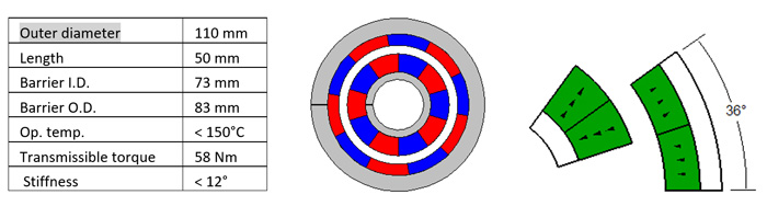
With this software program package, the design engineer sets up the model geometry taking advantage of its angular anti-periodicity. This way, only a 36°-slice is modeled for a 10-pole coupling. It is important to give thought to how magnet regions are represented, i.e. magnets should be partitioned along the centerline such that two 18° sections each from two neighboring magnets make into the model (as per Fig. 1). Note that the barrier is assumed non-magnetic and not shown.
Permanent magnet orientation direction is usually straight across, pointing out from or in toward the center for each magnet segment. This is different from being truly radial so as to be most economical and readily sourced. One side of the coupling (driver or follower) is rotated by 18° mechanical angle (90° electrical angle) with respect to the other side (follower or driver) for maximum transmissible torque. Segment lines on periodic boundaries are selected for assignment of an anti-periodicity boundary condition. The model is solved using FEA or BEA and the torque calculated. Note that the torque value reported is for the complete coupling assembly and not just for the 36° sector shown.

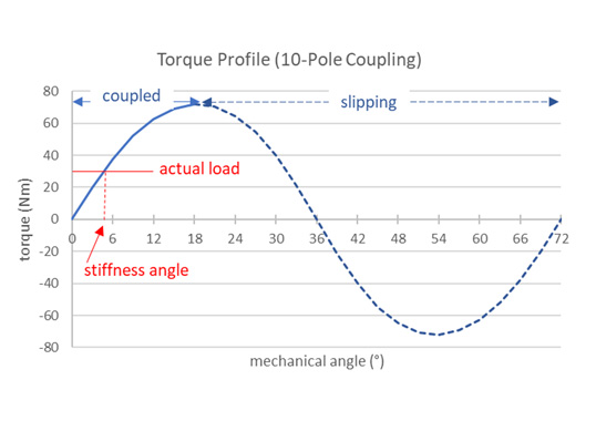
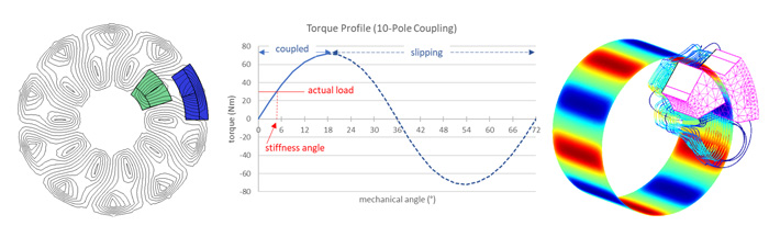
Changes to the model, e.g. in any of the diameters, magnet and backiron materials, operating temperature (affecting magnet Br and Hc properties), number of poles, etc., can be made to maximize torque (or minimize package size). Parametric analysis is employed, as necessary, to streamline the iterations and is helpful to plot torque versus angular displacement (between driver and follower) profile, across 0~18° mechanical angle (0~90° electrical angle) range (for 10-pole coupling), to understand torque characteristics and find the stiffness angle under a particular torque load.
The center shaft, and especially the outer backiron, are flux carriers and key components in the magnetic circuit. If made of low-carbon steel, they magnetically saturate at around 1.8T. The backiron is sized so that it operates slightly above saturation (~2.0T) to obtain the ‘most bang for the buck’.

3D Design
Since fringing (end) effect is not accounted for in 2D design, Lorentz-EM™ or Faraday™ software can be used for 3D analysis. Design parameters from the Inducto-2D™ model are transferred and the 3D model set-up. Angular periodicity and symmetry boundary conditions are both utilized, as necessary, to expedite the analysis. As the model is solved and the streamlines plotted, it becomes evident that magnetic flux lines toward the ends of the coupling bend out into the air instead of traveling through the magnetic components. These fluxes do not contribute to torque generation. Maximum torque calculated from the 3D model is 60 Nm (versus 72 Nm obtained from 2D model) and more realistic.
The barrier affects coupling torque in different ways. Should the barrier be made of magnetic material, it exhibits a shunting effect. This reduces the magnetic flux that travels from driver to follower (and vice versa), thereby reducing coupling torque. Alternatively, if the barrier is electrically conductive, any relative movement between barrier and driver/follower system will generate eddy current loss resulting in coupling torque loss. Eddy current loss can be analyzed using Inducto™ 2D or 3D.
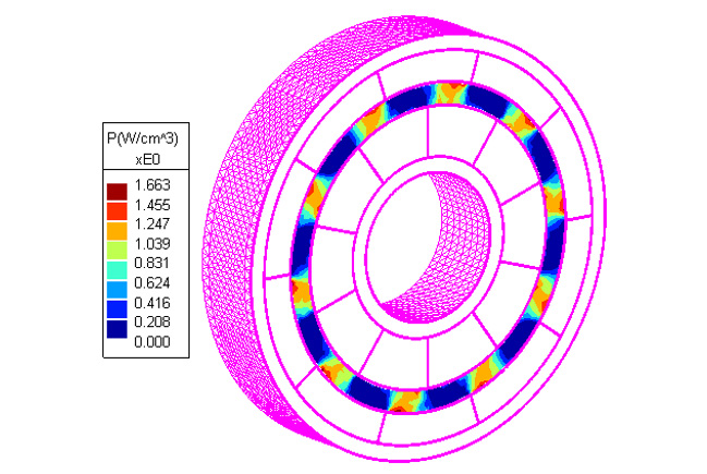
For example, with a Ti-6Al-4V titanium barrier and 500 rpm rotation speed, the eddy current loss in the barrier is calculated as 21 W, which amounts to 0.4 Nm transmissible torque loss to the coupling. Power density due to eddy current loss in the barrier region is then plotted, as shown in Fig. 3. As demonstrated, these electromagnetic analysis packages are ideal tools for magnetic coupling design.