While surge arresters are the foundation of insulation coordination and critical components in power systems, they are not always fully appreciated due to their standardized integration, relatively low complexity (compared to other equipment) and lower costs. Despite this, modern power systems could not operate reliably without high-quality metal oxide (MO) surge arresters. These play a vital role in sustaining both current and future power demands, especially as grids evolve with renewable energy sources and interconnected networks. Surge arresters help ensure an uninterrupted supply of electricity, even in the presence of overvoltages caused by lightning or switching surges.
This edited contribution to INMR by Florent Giraudet of Metarresters explains that the core of today’s surge arresters is the metal oxide varistor (MOV), which has become the backbone of surge protection devices for the electrical power industry. MOV technology, which became prevalent in the 1980s, is now dominant and its development reflects new challenges and innovations since that time. Today, there is ongoing R&D focused on improving performance, reliability and long-term stability, while also adapting to new applications.
Surge Arresters in Changing Energy Landscape
MOV technologies are adapting to best address evolution of electrical networks and other industry trends and thereby going beyond their original functions. For example, HVDC networks require compatibility with direct current and high energy absorption capabilities. The shift towards HVDC transmission for long-distance power transfer and complex applications such as interconnecting asynchronous networks and offshore wind farms has led to need for advanced HVDC circuit breakers. Specialized MOV applications play a major role in HVDC circuit breaker development, where these systems need to isolate faulted segments quickly without a natural current zero. This prevents large-scale outages and supports reliable operation of multi-gigawatt DC networks.
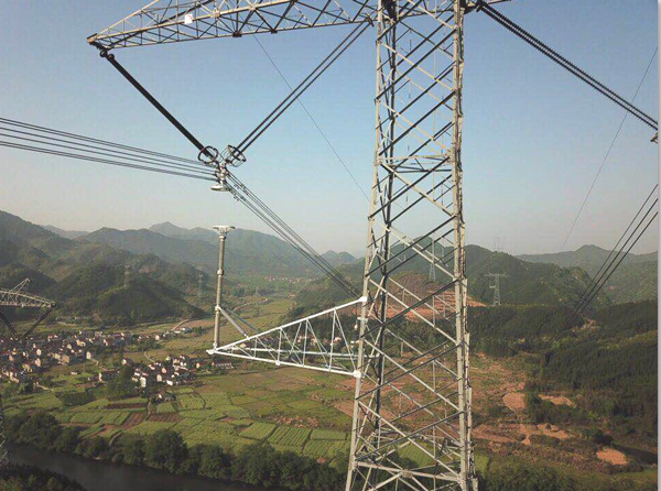
Similarly, interconnection of networks requires reconsideration of line architecture, prompting construction of new high voltage lines or upgrading existing ones to transport energy more reliably. Integration of renewable sources, often located far from urban centers, requires highly sensitive and reliable new transmission structures. These developments also demand innovations from surge arrester and MOV manufacturers to tailor make solutions to meet these demands.
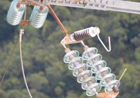
Moreover, in recent years line surge arresters, particularly externally gapped line arresters (EGLAs), have been garnering renewed attention. Previously overlooked, EGLAs are now experiencing a resurgence, leading to a re-evaluation of the role of MOVs. Unlike traditional MOV applications, which constantly experience voltage across their terminals, these newer applications require greater charge transfer capabilities to handle lightning discharges.
MOV Technology
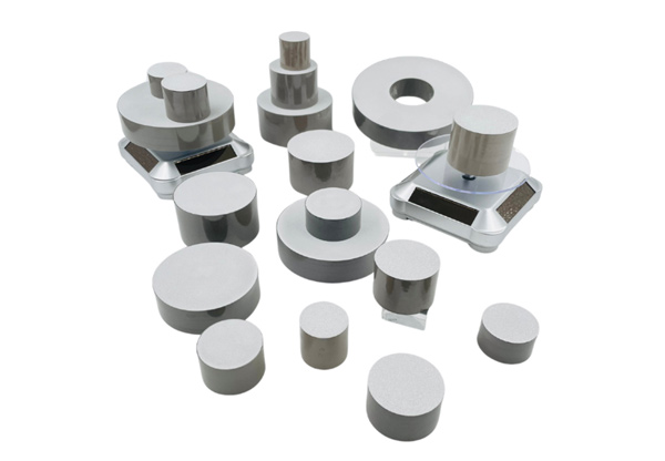
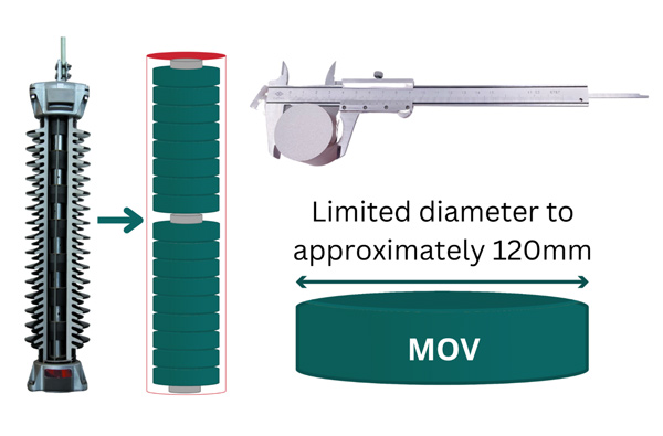
The core of every modern surge arrester is a simple assembly of MOVs. These MOVs are strategically stacked to form one or multiple columns, each designed according to specific requirements for protection levels (residual voltage), energy absorption capability, charge transfer ratings, and voltage ratings to handle temporary overvoltages.
While the number of MOVs in a single column typically correlates with voltage ratings, a full MOV stack can comprise multiple columns in parallel to achieve specific energy or charge ratings. Supporting current flow depends on having the right number of parallel paths within the MOV(s).
Ratings for energy, charge or protection levels are controlled by selecting appropriate MOV diameter or total number of parallel columns. For construction reasons, diameter is generally limited to circa 120 mm per MOV column. Multiple MOV columns can be contained within one or more surge arrester housings, depending on application. MOV diameter directly influences an arrester’s ability to handle high current densities from transient surges without sustaining damage.
Voltage ratings are essential for ensuring long-term stability of the MOV stack under continuous operating voltage or specific temporary overvoltage conditions. Although MOVs are not always under continuous voltage, this remains the case for most applications today.
Breakdown voltage of a boundary layer between two ZnO grains is approximately 3V, depending on structure. To reach the desired breakdown voltage for a specific application, an MOV must therefore contain the appropriate number of serial grain boundaries. However, due to limitations in production and testing, MOV height (independent of manufacturer) is generally restricted to about 45 mm. Therefore, in high voltage surge arresters, multiple MOV blocks are stacked vertically to meet performance requirements.
Manufacturing Process
In general, there are seven major steps involved in production:
1. Weighing & Mixing
The primary constituent of MOVs is zinc oxide (ZnO), making up roughly 90% of the total mass. The remaining 10% is comprised of oxide additives, which serve multiple functions, e.g. they fine-tune the non-linear V-I characteristics, control grain growth, maintain electrical stability of the MOVs and facilitate manufacturing. In this first step, the zinc oxide is mixed with additives, which are prepared in advance, depending on product specifications and requirements, to achieve different functions. In this regard, a typical MOV for an AC distribution system will not have the same constituents as an MOV for HVDC circuit breakers. A slurry is then obtained by incorporating organic solvents and binders.
2. Dehumidification or Spray Drying
Next, a dehumidification process (also known as spray drying) prepares the material by removing moisture. The slurry obtained during mixing is injected into spray dryers to remove the liquid content and yield a final powder. Production of oxidized granulation powder will directly affect the electrical properties of MOVs. Factors such as particle size of the granulation powder, internal temperature of the granulation tower and uniformity of various component concentrations can significantly impact MOV performance.
3. Pressing or Forming
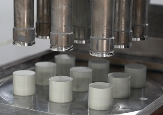
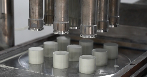
In this visually significant step, the dehumidified powder is pressed into the preliminary shape of the block. This dry pressing process is where the MOV begins to take form. At this stage, each block must be meticulously weighed and controlled to ensure precision and quality.
4. Pyrolyzing & Sintering
Once the MOV has its initial shape, it undergoes pyrolyzing and sintering in high-temperature tunnel furnaces. The pyrolyzing process removes organic solvents and binders from the block, resulting in a ‘green block’, due to the natural color of MOVs. In the subsequent sintering process, temperatures reach up to 1050°C, causing blocks to turn black externally, although the inner part remains green. This sintering step forms the grains and grain boundaries to meet desired electrical performance requirements. These processes remove certain compounds, causing the MOV to lose approximately 17% of its initial volume.

5. Passivation or Coating
In this step, a specialized passivation layer is applied to the lateral surface of the MOV. This layer is crucial for protecting the MOV from environmental factors and enhancing its flashover resistance. This is a highly sensitive process, requiring expertise to produce high quality MOVs. While different materials and processes can be used, glass coating represents the cutting edge MOV technology.
6. Surface Preparation & Electrode Application
After coating, the front surfaces must be smoothed to facilitate electrode application. These surfaces may not be entirely flat, since residual coating material can remain. A grinding machine, combined with water, achieves a completely flat surface, essential for the stacking process. Once a clean and flat surface is obtained, metal electrodes, often made of aluminum, are applied. The aluminum layer, typically about 0.1 mm thick, ensures proper conductivity between MOV blocks, allowing the energy or current impulse to be evenly distributed across the MOV surfaces.

7. Final Verification & Testing
Electrical tests are conducted to verify that the MOV meets specified characteristics for electrical performance and charge transfer capability. As in the case of a complete surge arrester, individual MOVs undergo typical electrical tests, such as reference voltage and residual voltage. For MOV manufacturers, an additional routine test — the long-duration current impulse test — is critical to ensure proper block characteristics, including the properties of the grains and boundaries. Reject rate is closely tracked at this stage.
Quality Control
Quality assurance & control is critical throughout the MOV manufacturing process, with several key steps designed to ensure consistent performance and reliability.
A primary focus is on incoming raw material inspection, especially the zinc oxide and various additives. Rigorous testing is applied to verify that all sub-suppliers meet stringent quality expectations, safeguarding the foundational integrity of the MOVs from the start.
Another critical control point is final powder inspection, conducted right before pressing and forming of the MOV blocks. Each batch intended for pressing undergoes extensive testing to confirm that the correct production processes were followed and that the oxidized granulation powder exhibits the necessary electrical properties. This is essential to maintain intended performance and prevent any compromise in reliability.
Beyond these initial controls, in-process testing plays a vital role in validating product consistency. Samples selected from each batch are subjected to specialized tests, such as high-current impulse and long-duration current impulse to ensure resilience under various operational stresses. Additionally, an accelerated ageing test, often referred to as the long-term stability test, is conducted to simulate extended performance and verify that the MOV blocks retain their properties over time.
These comprehensive quality assurance measures collectively uphold MOV reliability, ensuring that each unit is ready for demanding applications in power systems.

Conclusion: Unsung Heroes of Power Grids
Surge arresters and metal oxide varistors (MOVs) are essential, foundational components that sustain the reliability and resilience of modern power systems. As grids evolve to meet the demands of renewable energy, interconnected networks, and advanced technologies such as HVDC transmission, MOVs are being adapted to meet these challenges, highlighting both their versatility and importance.
Understanding the ‘journey’ of MOVs—from meticulous mixing of raw materials to precise final testing—highlights the expertise and commitment embedded into each protective component. These processes ensure that MOVs can withstand extreme conditions and perform their crucial function, i.e. safeguarding power systems against disruptive surges.
MOV technology remains a quiet guardian, but one without which the stability of the electrical grid would be compromised. With every new advancement, MOVs continue to fortify energy infrastructure. In this regard, it is correct to think of them as unsung yet indispensable heroes of the the modern power landscape.
Learn more by watching this 25-min educational video on MOV technology and Surge Arresters:

