As explained in this edited past contribution to INMR by Prof. Ravi S. Gorur, composite insulators are now a mature technology with service experience of about 50 years. Silicone rubber has become the material of choice for housings and failures due to inherent weaknesses in materials, processing, design, or manufacturing have mostly been eliminated. While sporadic cases of failure still occur, most can be traced back to factors such as misapplication, improper storage, mishandling, or insufficient quality control during production.
Yet some users are still reluctant to specify composite insulators for critical transmission lines. To overcome such hesitation, certain issues remain to be addressed, including:
1. condition assessment to determine suitable maintenance practices and safety of live-line working, and
2. better ranking the different designs to help utility engineers develop more comprehensive specifications.
Resolving these issues will increase confidence in composite insulators to the same level as porcelain and glass and the only criterion for selection of insulator technology will become life-cycle cost. In this regard, it is expected that all insulator technologies will remain valid since each has its own unique advantages and also limitations. Users will probably find that a combination of different insulator technologies provides the most cost-effective solution for their applications.

Composite insulators for transmission voltages were launched during the 1970s and some of these early designs are actually still in service. Composite insulators today are mature products, with life expectancy comparable to porcelain and glass and suitable for use at all voltage levels for line as well as substation applications. Their main advantages are:
1. Non-brittle and light to help lower construction costs;
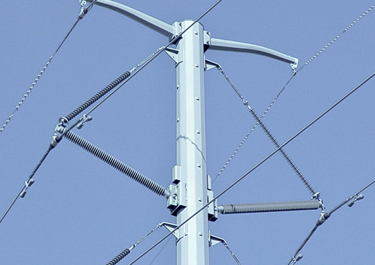
2. Ideal for compact line construction with line post insulators that reduce right-of-way requirements and provide other cost savings; 3. Improved seismic, safety and contamination performance at substations.
Constructional Aspects
The following are the main aspects of composite insulators design and construction:
Core Rods
For suspension insulators, both E-glass and E-CR (electrical grade, corrosion resistant) glass reinforced cores are offered. The number of insulator manufacturers that use E-CR cores has increased while for line post and apparatus insulators, an E-glass core is basically standard.
Housing
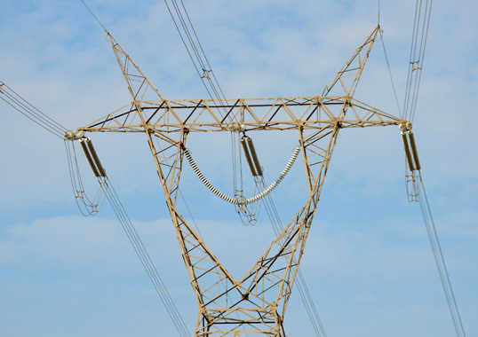
The silicone rubber family is the material of choice for transmission voltages and also for apparatus with a large range of different formulations available. The most common designs feature alternating shed diameters.
End Fittings
Crimped on (or swaged) end fittings are used for line insulators and many suppliers employ special equipment to detect rods that crack if not performed properly. While this quality control check can detect rods with serious cracking, cracks that are not advanced could go undetected. This has contributed to brittle fracture failures where the origin has been found to be within the end fitting.
Rod-Housing Interface
Direct bonding between rod and housing material is by far the most common. Use of a live interface with the space between rod and housing filled with a silicone compound has also been employed for some transmission insulators.

Service Experience
Overall service experience has been excellent and periodic failures have been due mostly to factors stemming from human error during quality control, storage, handling and installation. Principal failures modes are:
Brittle Fracture
This is the most serious type of failure since it can lead to line drop. Such failures have occurred on suspension insulators at all transmission voltages, starting from 115 kV. Some have been found to be due to misapplication, such as installing 230 kV insulators at high altitudes without corona rings; others have occurred at voltages from 115 kV to 161 kV where in the past it was thought that corona rings were not required.
Such failures have alerted users and manufacturers alike that corona rings are recommended even at voltages from 69 kV to 161 kV, depending on location and configuration (e.g. dead-end structures). There have also been documented cases of brittle fracture of line post insulators. Even though this is rare, it is nevertheless important since the rods involved are much larger (i.e. 75 mm to 90 mm) compared to suspension insulators (16 mm to 30 mm). Brittle fracture of large line post insulators was initially thought to be almost impossible.
Mechanical Failure in Coastal Locations
Past cases of composite insulator failures in severely polluted conditions have been linked to erosion of the housing due to high discharge activity. This erosion exposed the core rod, causing subsequent tracking and burning, and has occurred at voltages from 161 kV to 500 kV.
Some utilities have therefore decided to employ RTV-silicone coated glass or porcelain insulators in areas of heavy contamination, expecting to combine surface hydrophobicity with the stability of an inorganic dielectric. Should hydrophobicity be lost and leakage current activity increase to levels that degrade the coating, the underlying glass or porcelain body (unlike the FRP core rod of a composite insulator) is resistant to discharges.
Ageing
Ageing or gradual reduction in key properties due to electrical, mechanical and environmental stresses was once considered a major factor limiting useful life of composite insulators. A variety of material and product test procedures were developed and many are now part of national and international standards. Weaknesses in material properties can largely be compensated for by adequate leakage distance as well as proper shed spacing. Composite insulators that comply with all standards and employ conservative design principals have typically not experienced failure linked to premature ageing.
User Concerns
Core Specification
Users are long accustomed to toughened glass and porcelain and all aspects of these insulators have been standardized. Users need only mention the relevant standard and they feel assured that the product will perform for the intended application. In general, this same comfort level does not always exist for composite insulators due to their more recent entry onto the market. Development of this technology also coincided with many utilities losing experienced staff due to retirement, attrition and downsizing. Consequently, most users have come to rely on manufacturers as well as independent test laboratories for many aspects. For example, while ASTM standard D 578 for glass fiber strands provided the chemical composition range of E-glass fibers, variations were still possible (see Table 1).
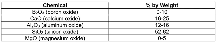
Boron is responsible for the weak chemical resistance of glass, especially to acids, and brittle fracture of composite insulators has been largely attributed to this. Elimination of boron is therefore key in E-CR glass – the ASTM nomenclature ‘for boron-free modified E-glass compositions for improved resistance to corrosion by most acids’. Glass manufacturers state that resistance of E-CR glass to acids is about 7 times greater than for E-glass.
Removal of boron requires equipment that tolerates high temperature and therefore E-CR glass is more costly than E-glass. Moreover, removal of defects (or seeds) from E-CR glass fibers is also more difficult than with E-glass. Some core rods made of E-CR glass have in the past been found to contain voids within the fibers that could lead to punctures and premature failure due to partial discharge. E-CR glass cores exposed to the environment due to defective or inadequate seals or damage to the housing will fail by tracking in a short time. This is true for E-glass as well. As such, specifying E-CR glass alone will not eliminate all failures of composite insulators but rather only delay the time to failure by this mode. At the same time, it will do nothing to eliminate other kinds of rod failure due to puncture, tracking and burning.
Simple visual observation is sufficient to realize that differences exist in compositional details of both the E-glass and E-CR glass in use today. Detection of boron content is challenging due to its low atomic weight. Specialized equipment such as a scanning electron microscope with energy dispersive x-ray analyzer and a trained operator are essential. Similarly, there is no standard test to evaluate resistance to brittle fracture.
Experienced users of composite insulators typically have the data and knowledge to evaluate differences that can arise from use of different core rods. However, it may present a problem for new users and increase their reluctance to purchase composite insulators.
Housing Material
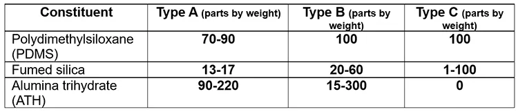
The family of silicone rubber consists of numerous varieties of 1. high temperature vulcanized (HTV or HCR) compositions; 2. room temperature vulcanized (RTV) compositions; and 3. liquid silicone rubber (LSR) based compositions. All find use as housings for insulators.
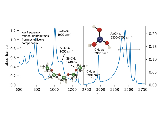
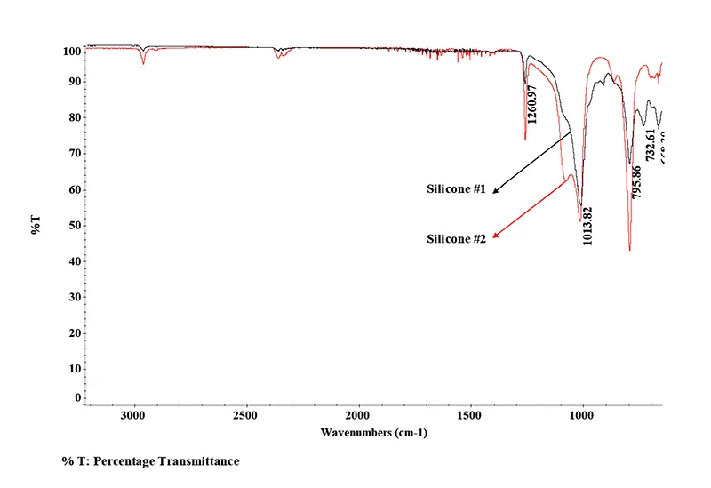
Fig. 1 shows the infrared spectrographs of two silicone housings from commercial insulators and clear differences are evident in details of their formulations. Several ingredients are used to achieve desirable properties and also to control cost. Table 2 shows that wide variation is possible in the three major constituents used in these types of silicone rubber for outdoor applications. Moreover, a large number of different formulations are possible for each type as well.
Performance and cost are known to depend on formulation yet specifying composition is beyond the expertise of average users. At the same time, standardizing formulation details is not desirable since this will stifle innovation. Since manufacturers sometimes make formulation changes that are not always performance related, there may be a need to establish minimum requirements and quick diagnostic tests to confirm that these are being satisfied by every batch of products. While meeting IEC 61109 test requirements for materials is an acceptable minimum, it does not help users to rank alternative housings and select the best product since all will probably pass. With so many formulations of silicone rubber currently available, technical data may be needed to assist utilities in evaluating the pros and cons of each and making the best selection. For most service locations, selecting a generic silicone rubber composition and design may prove sufficient. But for special locations and critical lines, it is prudent to select the best product available.

Corona Ring Design
The corona ring accounts for a significant share of an insulator’s total manufacturing cost and is also important for the user since it can have a major bearing on performance and service life. Generally, manufacturers all have different corona ring designs in aspects such as cross-sectional diameter, ring diameter, height from point of mounting, method of attachment, material, method of manufacture and test method used to qualify performance. Sophisticated 3-D computational packages are routinely used for corona ring design that consider asymmetries introduced due to factors such as conductor and tower hardware, presence of water droplets, etc. But these are time consuming tasks and require skilled professionals. By providing a safe upper limit of electrical stress, ring dimensions can be optimized. Final design is ultimately verified by laboratory tests using corona detection cameras.
The corona inception and extinction voltages with new rings having polished surfaces will be higher than for a weathered ring in the presence of moisture and contamination as is more typical of actual service. It is therefore important to perform testing under realistic conditions and these should become part of the corona test standard.
Condition Monitoring
Perhaps the greatest impediment to even more widespread application of composite insulators on critical transmission lines is assessing their condition in service. National safety codes require establishing minimum distances prior to live line working. For glass and porcelain string insulators, this translates into a certain number of discs that are electrically sound. Due to differences in constructional aspects (i.e. absence of intermediate metal electrodes), diagnostic tools developed to identify punctured porcelain are not suitable to detect composite insulators with hidden defects. In most parts of the world, the transmission network is a major bottleneck with most lines operating to capacity. Taking a line out of service for maintenance is costly and often not feasible. Hence utilities follow one or more of the following approaches:
1. Selecting only high quality insulators with a proven record of reliability;
2. Specifying only insulators of the type that can easily be detected if they become defective; and
3. Choosing only insulators that permit live-line working.

Developments in Condition Monitoring
There are three methodologies that have undergone successive improvement over the years:
1. infrared (IR) thermography;
2. electric field probe; and
3. corona detection using UV cameras.
Each has advantages and limitations and is based on different phenomena so a combination of these may be ideal to confidently identify all faulty composite insulators in service.
IR thermography helps to indicate the presence of any internal conductive defects. For example, partial tracking along the core rod or the presence of moisture in the rod or rod-housing interface could both be detected by higher temperatures in these regions. Such inspection can be done from the ground. An electric field probe can also identify hidden defects such as tracking or torn sheds. However, such inspection needs to be done from the tower cross-arm or from a bucket truck. Corona cameras can be used from the ground to detect presence of corona near an insulator. These cameras are operable even in daylight.
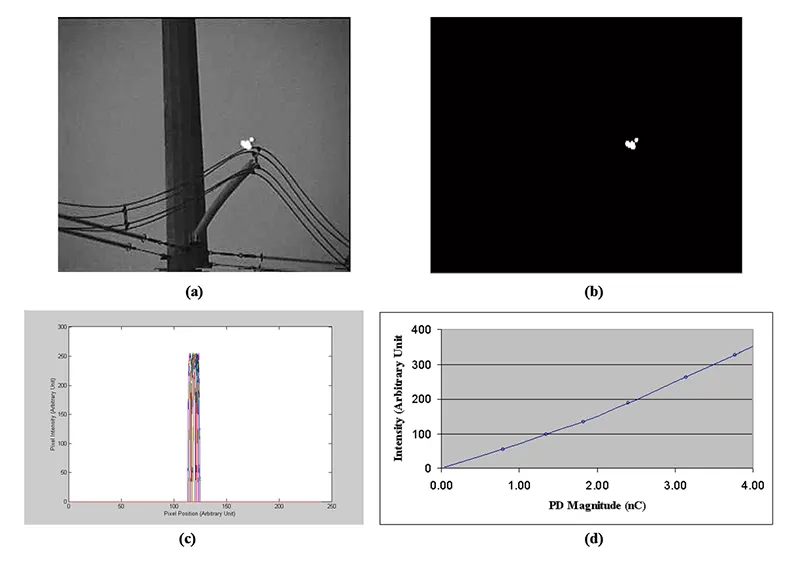
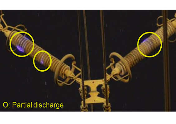
These techniques are increasingly refined, and work has progressed toward the goal that they provide a clear ‘go/no-go’ decision. For example, in the past it has not been possible to measure discharge intensity using a corona camera image. If this could be estimated, line inspection personnel would be in a much better position to assess whether the corona is damaging to the material or not.
Fig. 2 presents past research aimed at quantifying corona images. Based on a combination of processing corona images obtained from field inspection and partial discharge measurements in the laboratory, it was possible to estimate discharge magnitude. Such information, along with corona tests on materials, can then be used to estimate damage limits and assess insulator condition.

Laboratory Testing
Significant developments have occurred in the last 25 years with regards to evaluating contamination performance and ageing in a multi-stress environment. These tests are not standardized due to elaborate experimental features and proprietary details by those who developed them. It is therefore difficult to have several laboratories perform the same test to meet the criterion of reproducibility. Still, each such test will provide important information about expected performance in service.