As in places such as Japan where lightning accounts for more than 50% of power system failures, a high proportion of all transmission line trippings in China are due to lightning strike. For example, operating data for 500 kV lines across five provinces within the China Southern Power Grid showed that, of the 62 total trip-outs registered during one year, 87% were linked to lightning. Moreover, average lightning trip-out rate on this transmission grid over a recent five-year period stood at about 62% of all trip-out faults.
Fortunately, polymeric zinc oxide surge arresters have been developed since the 1980s and are now increasingly put into service on transmission lines. In parallel with insulators, these deliver excellent performance in terms of limiting such overvoltages and improving lightning performance of transmission lines. This edited past contribution to INMR by Professor HE Jinliang of the Dept. of Electrical Engineering at Tsinghua University in Beijing, offered a Chinese perspective on key issues in lightning protection using transmission line surge arresters.

Series Gap Design Line Surge Arresters
Design of the series gap in a line surge arrester includes selecting the gap structure as well as determining length of the gap, which directly determines protection characteristics. Gap distance between the two electrodes of the arrester must remain basically unchanged under all external forces such as wind or conductor swing. This is necessary to keep the discharge voltage across the series gap stable and within only a small dispersion.
Two different types of series gap structures have been developed. The first is the separated gap, designed in Japan, where the two discharge electrodes are isolated only by air. The second is called the fixed or integrated gap, whereby the two discharge rings are fixed using a composite insulator. This keeps their distance unchanged, even under conditions such as heavy wind loading. The fixed gap also means that the arrester unit and the series gap are assembled into a single body, as shown in Fig. 1a. Ordinarily, a composite insulator is fixed to the bottom of the arrester and two ring-shaped discharge electrodes are fixed onto the insulator’s two terminals. The advantage of this kind of series gap is that the distance between the two electrodes can no longer be influenced by external factors. Most of the transmission line arresters used in China have adopted this type of series gap.
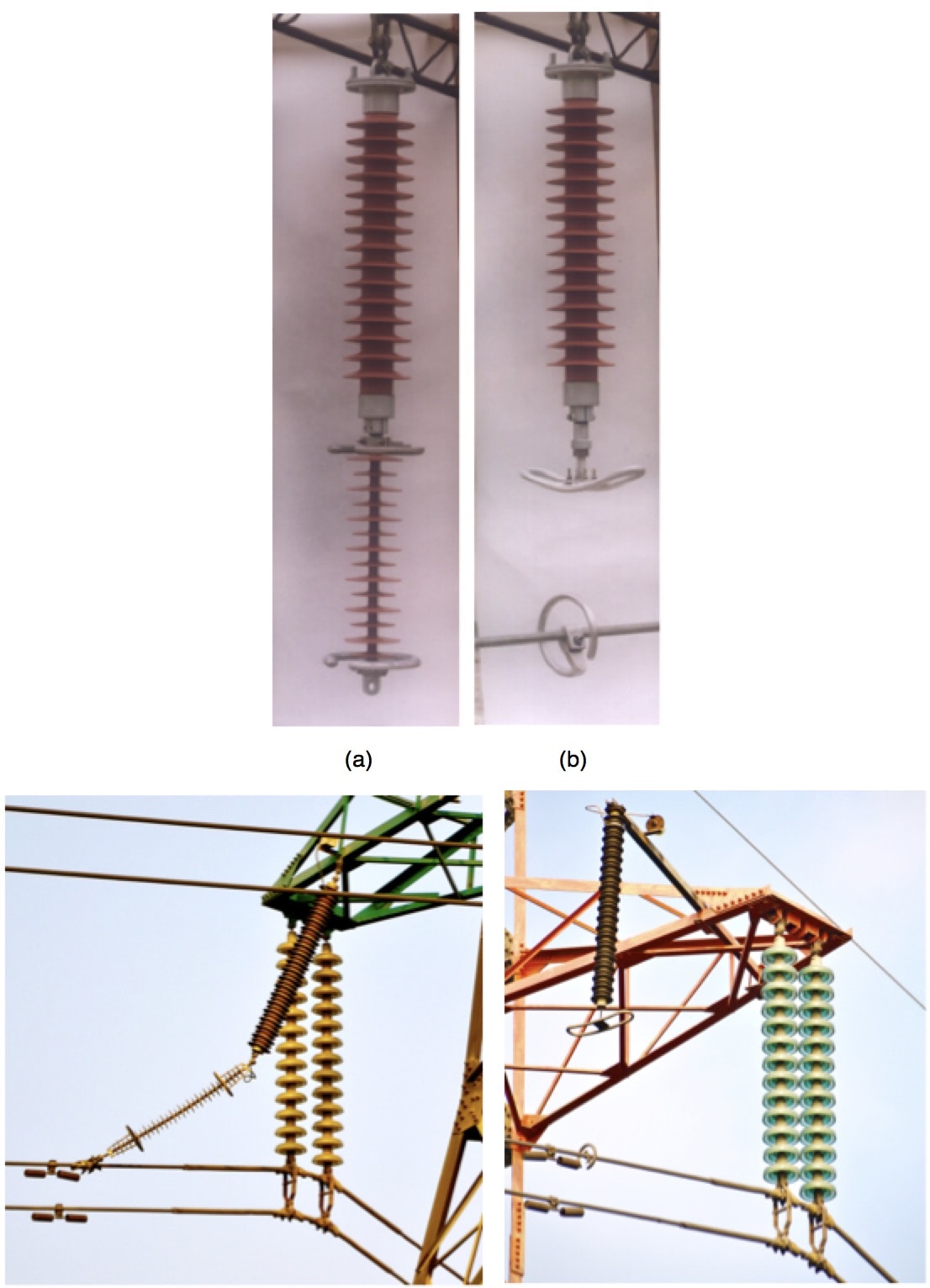
In the case of the separated gap design, one of the discharge electrodes is fixed to the bottom of the arrester while the other is fixed onto the phase conductor. As discussed, the gap separating the two discharge electrodes must be constant, even under the influence of various external factors. To ensure this distance remains unchanged, discharge electrodes should ideally be manufactured in a complex arc shape, as in Fig. 1b. Japanese line surge arresters for 77 kV, 275 kV and 500 kV applications employ this kind of series gap.
Since the fixed gap design line arrester is supported by a composite insulator, the power frequency operating voltage applied to the arrester and the fixed gap during normal operating conditions is calculated based on their capacitances. For example, the capacitance of the fixed gap of a 110 kV line surge arrester with 500 mm length is 0.4 pF while the capacitance per 70 mm diameter ZnO disk is 1040 pF. There are 28 disks used in such an arrester and total capacitance is 37 pF.
The composite insulator fixing the series gap must be able to endure almost all the continuous operating voltage. Since the insulators employed in China for 110 kV fixed gap line arresters are the same as used for 35 kV applications, potential problems with these insulators include degraded performance due to ageing under continuous power frequency overvoltage. As such, the composite insulator can become the weak point of a polymeric line arrester with fixed gap design. Nevertheless, this design may still prove the preferred choice to increase overall operating stability.

Insulation Coordination of Line Arrester with Insulator String for Lightning Protection
The principles necessary to determine correct gap distance include:
(a) Coordination of lightning impulse discharging voltages between insulator string and line arrester. The 50% discharge voltage of the insulator should be 20% higher than the discharge voltage of the line arrester.
(b) The line arrester should withstand switching impulse overvoltage without discharging and the series gap should withstand switching impulse if the arrester has failed;
(c) Conversely, the line arrester should withstand 1.4 times power frequency overvoltage for 1 minute, e.g. 444 kV in the case of a 500 kV line surge arrester. The line arrester should also be able to cut off the AC power frequency follow current.

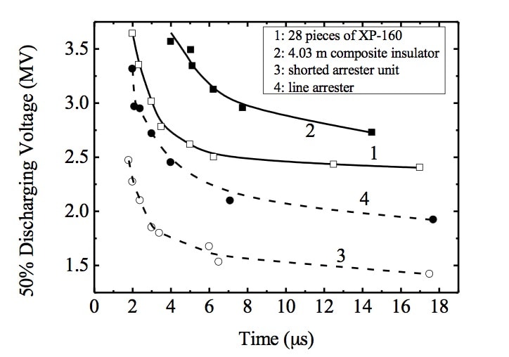
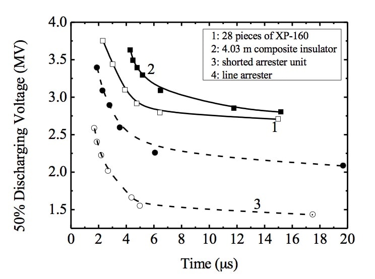
When line surge arresters are installed for lightning protection of transmission lines, the insulators being protected should not experience flashover during lightning strikes. This way, the lightning impulse voltage versus time characteristic curve of the arrester with series gap and that of the insulator string should be approximately in parallel, with no crossover point. Table 1 illustrates tested 50% lightning discharge voltages of insulators and arresters. The 50% lightning discharge voltages of the arrester under positive or negative lightning strike are 20% less than that of the composite insulator. This therefore satisfies requirements for their insulation coordination. The 50% lightning discharge voltage of a porcelain insulator is 18% higher than that of the arrester under positive lightning when the series gap is set at 1800 mm. However, considering a 3% discharge deviation and comparing the discharge voltage ratio based on the 50% lightning discharge voltage of the arrester, the 50% lightning discharge voltage of the arrester still satisfies the demands of insulation coordination. As such, if the series gap distance of the line arrester is set at 1800 mm, it can coordinate with either porcelain or composite insulators.

Figs. 2 and 3 respectively compare the lightning impulse characteristics of insulator and line surge arrester with series gap of 1800 mm. Under positive or negative lightning strike and with a series gap of this length, the voltage-time characteristic of the arrester coordinates well with those of both composite and porcelain insulators. When gap length increases to 2000 mm however, as shown in Figs. 6 and 7, the arrester will no longer coordinate well with the insulator under positive lightning. The correct gap distance is thus determined as 1800 mm. Moreover, it has been observed that the voltage-time characteristic of the line arrester can be well coordinated with that of the insulator if the arrester unit has failed.
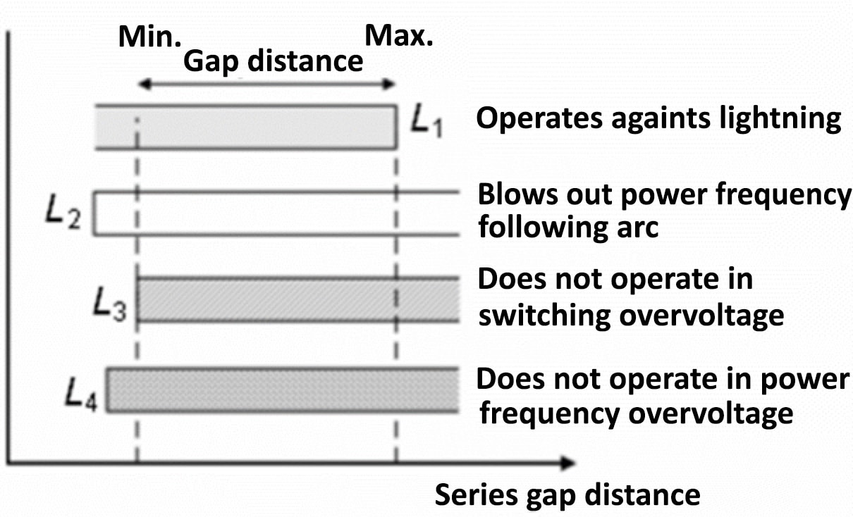
In addition to insulation coordination of line arresters with insulator strings for lightning protection, the arrester’s series gap length should also have suitable withstand capability in regard to power frequency and switching overvoltages. As illustrated in Fig. 4, required lengths of the series gap for different purposes are not the same. For example, in order to suppress lightning overvoltage, length of the series gap should be set shorter than L1 while, to extinguish power frequency follow current, length of the series gap must be longer than L2. Moreover, length of the series gap must be longer than both L3 and L4 to guarantee that the arrester does not operate under switching or power frequency overvoltage.
In the case of 500 kV line arresters where length of the series gap is 1800 mm, positive switching impulse 50% discharge voltage reaches 1676 kV. The wave of the applied switching impulse voltage is 250/2500 ms and both negative and positive switching impulse withstand voltages of the series gap exceed 1000 kV. Even if the arrester has failed, the negative and positive switching impulse withstand of the series gap still reach 950 kV. This satisfies the insulation coordination requirements discussed above and a line arrester with series gap of 1800 mm can therefore be suitable for application on 500 kV transmission lines with 1.8 times statistical switching overvoltage.
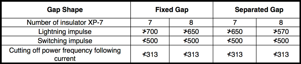
A line arrester must also withstand 1.4 times power frequency AC overvoltage for 1 minute, i.e. applied voltage of 444 kV (effective value), and line surge arresters being developed have passed this test. Detailed values of required series gap lengths for a 110 kV line surge arrester are shown in Table 2. As shown, fixed and separated gaps lengths determined in the case of these arresters should be 550 mm and 500 mm (±5%). Table 3 shows performance parameters for line arresters with series gaps.
Distance Between Line Arrester & Insulator String
A line surge arrester must maintain its distance from insulator strings installed in parallel. If the line arrester is located too close to the insulator string, lightning discharge would take place in the gap between the upper discharge ring of the line arrester and the bottom grading ring of the insulator string, such that no discharge occurs across the arresters’ series gap. In such cases, the insulator string can flashover and the line arrester has not provided the protection required for the insulator. This phenomenon, called ‘transverse discharge’, is caused by the proximity effect of the line arrester’s discharge ring and has been simulated in high voltage laboratories.
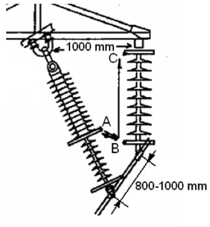
In the typical arrangement of a 110 kV line arrester, as shown in Fig. 5, there is a distance of about 1 m between the suspension locations of the arrester and insulator. Since the arrester in this case is about 1 m long and the series gap between its two discharge rings is 0.56 m, total arrester length is about 1.5 m. Yet insulator string length is only about 1.1 m. Therefore the longer line arrester must be installed inclined such that the distance between the fixing locations of the arrester and the insulator with phase conductor is about 0.8 to 1.0 m. Discharge ring diameter for a 110 kV line arrester is 0.245 m. As such, the closest point between the upper discharge ring (A) of the arrester and the bottom grading ring (B) of the composite insulator is only about 0.6 m. This is much less than 1.0 m distance between the suspension locations of the arrester and the insulator string. Distance between A of the line arrester and C of the insulator’s upper grading ring is less than 0.8 m.
The gap between the two discharge rings or grading rings can be treated as for a conductor-conductor gap. But the gap between discharge ring A of the line arrester and grading rings B or C of the insulator string must be treated as an arc conductor to arc conductor gap, similar to a special rod to rod gap. If the line arrester is located too close to the insulator string, electric field in this gap becomes distorted by the influence of the discharge and grading rings. Discharge across this gap then becomes easier than across the gap between the arrester’s two discharge rings. Basically, if the distance between line arrester and insulator string is small, lightning discharge takes place across gap AB, between the arrester’s upper discharge ring (A) and the insulator’s bottom grading ring (B) such that there is no discharge across the arrester’s series gap, i.e. the ‘transverse discharge’ phenomenon. In this case, the arrester unit of the line arrester is put into operation and protects the insulator string although the discharge gap does not function. Moreover, due to the proximity effect of the arrester’s upper discharge ring, the lightning impulse flashover voltage of the insulator decrease substantially compared to what it would be without this effect.
If the insulator string is polluted, its lightning flashover voltage under humid conditions is low. When lightning strikes the tower, transverse discharge takes place in the gap AB. Since the residual voltage of the arrester under high lightning current is high, grading ring B of the insulator has the same high potential as discharge ring A of the arrester. As a result, with the superposition effect of the AC power frequency phase voltage, flashover would take place through the insulator string, meaning the discharge route would be: A→B→C. If lightning strikes the phase conductor, this is a shielding failure and transverse discharge will be from B to A and flashover takes place through the insulator string from B to C, i.e. the discharge routes would be: B→A and B→C. Thus, the protection of the line arrester is rendered ineffective even though the arrester portion of the line arrester is still put into operation. Finally, when a line arrester is located very close to the insulator string, lightning discharge would take place in the gap AB as well as in gap AC between the upper discharge ring A of arrester and the upper grading ring C of the insulator. In this situation, if lightning strikes the tower, the discharge route would be: C→A→B. If lightning strikes the conductor, the discharge route would be: B→A→C. During the discharge, flashover may pass through a portion of the insulator string’s surface. In such case, the line arrester does not function as intended and gives no protection to the insulator string.
As mentioned, the transverse discharge phenomenon has been simulated in the high voltage laboratory. Experimental results suggest that minimum horizontal distance between the lateral portions of a line arrester and the insulator should be greater than 0.8 m for a 110 kV line and 1.3 m in the case of a 220 kV line.

High Voltage Gradient ZnO Varistors for Line Arresters
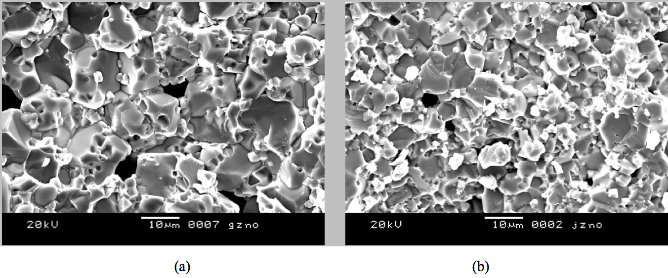
Since the line surge arrester is typically longer than the insulator string in parallel, it has proven challenging to install these arresters on transmission lines. This has motivated development of high gradient ZnO varistors so as to shorten the length required by these units. Usually, commonly used ZnO varistors have a voltage gradient of 200 V/mm. However, electrical and structural parameters of such varistors can be modified by doping with various rare earth oxides. When such oxides are added to ZnO varistors, growth speed slows due to stabilization of new spinel phases formed in the grain-boundary and grain size becomes smaller. Innovative ZnO varistor samples sintered with such optimized additives have a voltage gradient of 492 V/mm and a non-linearity coefficient of 76. Yet their leakage current is only 1 mA, meaning it becomes easier to control length of surge arresters. Fig. 6 shows scanning electron microscope (SEM) images of conventional and high voltage gradient ZnO varistors.
Line Surge Arrester Development & Application in China
Polymer-housed surge arresters for 6 kV and 10 kV distribution networks were developed in China in 1988 and now virtually all newly installed such arresters are polymeric. Suspended-type polymeric arresters without gaps used for 110 kV and 220 kV transmission lines and substations to suppress lightning and switching overvoltages were developed in 1992 and several such 110 kV arresters were put into operation at a substation the following year. Development of 110 kV and 220 kV polymeric transmission line arresters with gaps took place in China in May 1995 and 500 kV arresters with series gap for transmission line application were developed by Tsinghua University in September 1999 and applied in the field shortly thereafter. For example, the 500 kV Chang-Fang compact transmission line was put into operation in November 1999. Compared with conventional 500 kV transmission lines, capacity increased 34% to 1340 MW while right of way was reduced to only 17.9 m. The conductors of the three phases of this line are all arranged within the same tower window, without use of cross-arms, and phase-to-phase clearance is therefore greatly reduced from 12.3 m in the case of conventional lines to only 6.7 m. The number of sub-conductors is 6 and total bundle diameter is 750 mm. Since this compact line passes through a mountainous area with very high soil resistivity, the impulse grounding impedances of grounding devices for towers was also very high. As a result, it was decided to install line surge arresters to improve the line’s lightning protection performance.
Maximum allowed switching overvoltage on Chinese 110 kV to 220 kV power networks is 3.0 pu and polymer-housed gapless arresters are used in such applications mainly to limit lightning overvoltage. However, for 330 kV and 500 kV power networks, permitted overvoltages become 2.2 pu and 2.0 pu respectively and polymer-housed gapless arresters are used in this case to limit both lightning and switching overvoltages.
Since 1995, polymer-housed metal oxide arresters with series gaps have been developed and put into service on 35 kV, 66 kV, 110 kV, 220 kV, 330 kV and 500 kV networks. These types of line arresters are used only to limit lightning overvoltages.
References
• Furukawa, O. Usuda, T. Isozaki, and T. Irie, “Development and application of lightning arresters for transmission lines,” IEEE Transactions on Power Delivery, Vol. 4, no. 4, pp. 2121-2129, Oct. 1999.
• Jinliang He, Xi Wang, Zhanqing Yu and Rong Zeng, “Statistical Analysis on Lightning Performance of Transmission Lines in Several Regions of China,” IEEE Transactions on Power Delivery, Vol.30, no.3, pp.1543-1551, June 2015.
• E. Koch, J.A. Timoshenko, J.G. Anderson, and C. H. Shih, “Design of zinc oxide transmission line arresters for application on 138 kV towers,” IEEE Trans. Power Apparatus and System, Vol. 104, no. 10, pp. 2675-2680, Oct. 1985.
• J. Tarasiewicz, F. Rimmer, A. S. Morched, “Transmission line arrester energy, cost, and risk of failure analysis for partially shielded transmission lines,” IEEE Transactions on Power Delivery,vol.15, no.3, pp.919-924, July 2004.
• Sadovic, R. Joulie, S. Tartier, E. Brocard, “Use of line surge arresters for the improvement of the lightning performance of 63 kV and 90 kV shielded and unshielded transmission lines,” IEEE Transactions on Power Delivery, vol.12, no.3, pp.1232-1240, July 1997.
• Ishida, K. Dokai, T. Tsozaki, T. Irie, T. Nakayama, H. Fujita, K. Arakawa, Y. Aihara, “Development of a 500 kV transmission line arrester and its characteristics,” IEEE Transactions on Power Delivery, vol.7, no.3, pp.1265-1274, July 1992.
• Yamada, J. Sawada, E. Zaima, T. Irie, T. Ohashi, S. Yoshida, T. Kawamura, “Development of suspension-type arresters for transmission lines,” IEEE Transactions on Power Delivery, vol.8, no.3, pp.1052-1060, July 1993.
• J. L. He, R. Zeng, S. M. Chen, Z. C. Guan, “Potential distribution analysis of suspended-type metal-oxide surge arresters,” IEEE Transactions on Power Delivery,18, no.4, pp.1214-1220, Oct. 2003.
• J. L. He, R. Zeng, S. M. Chen, P. Tu, “Thermal characteristics of high voltage whole-solid-insulated polymeric ZnO surge arrester,” IEEE Trans. on PWRD, vol.18, no.3, pp. 1221-1227, July 2003.
• Jinliang He, Shuiming Chen, Rong Zeng, Jun Hu, and Chenggang Deng, “Development of Polymeric Surge ZnO Arresters for 500-kV Compact Transmission Line,” IEEE Transactions on Power Delivery, vol.21, no.1, pp.113-120, Jan. 2006.
• Jinliang He, Jun Hu, Shuiming Chen, and Rong Zeng. Influence of Series-Gap Structures on Lightning Impulse Characteristics of 110-kV Line Metal-Oxide Surge Arresters. IEEE Transactions on Power Delivery, vol.23, no.2, pp.703-709, April 2008.
• Jinliang He, Jun Hu, Yonghua Chen, Shuiming Chen, and Rong Zeng, “Minimum Distance of Lightning Protection between Insulator String and Line Surge Arrester in Parallel,” IEEE Transactions on Power Delivery, vol.24, no.2, pp.656-663, April 2009.
• Jinliang He, Jun Hu, Yuanhua Lin, “ZnO Varistors with High Voltage Gradient and Low Leakage Current by Doping Rare-earth Oxide,” Science in China, Series E, Technological Sciences, vol.51, no.6, pp.693-701, Jun. 2008.
[inline_ad_block]