The Belgian transmission system is an integral part of the European Network of Transmission System Operators (ENSTO-E). It was therefore vital that the country’s TSO, Elia, made provisions for increasing energy imports and exports. Another key driver has been providing capacity to cope with the planned closure of nuclear plants by 2025 along with the associated expected increase in renewables. This edited past contribution to INMR by Jean-François Goffinet of Elia, discussed experience with insulated cross-arms gained during the Stevin Project.
Stevin Project
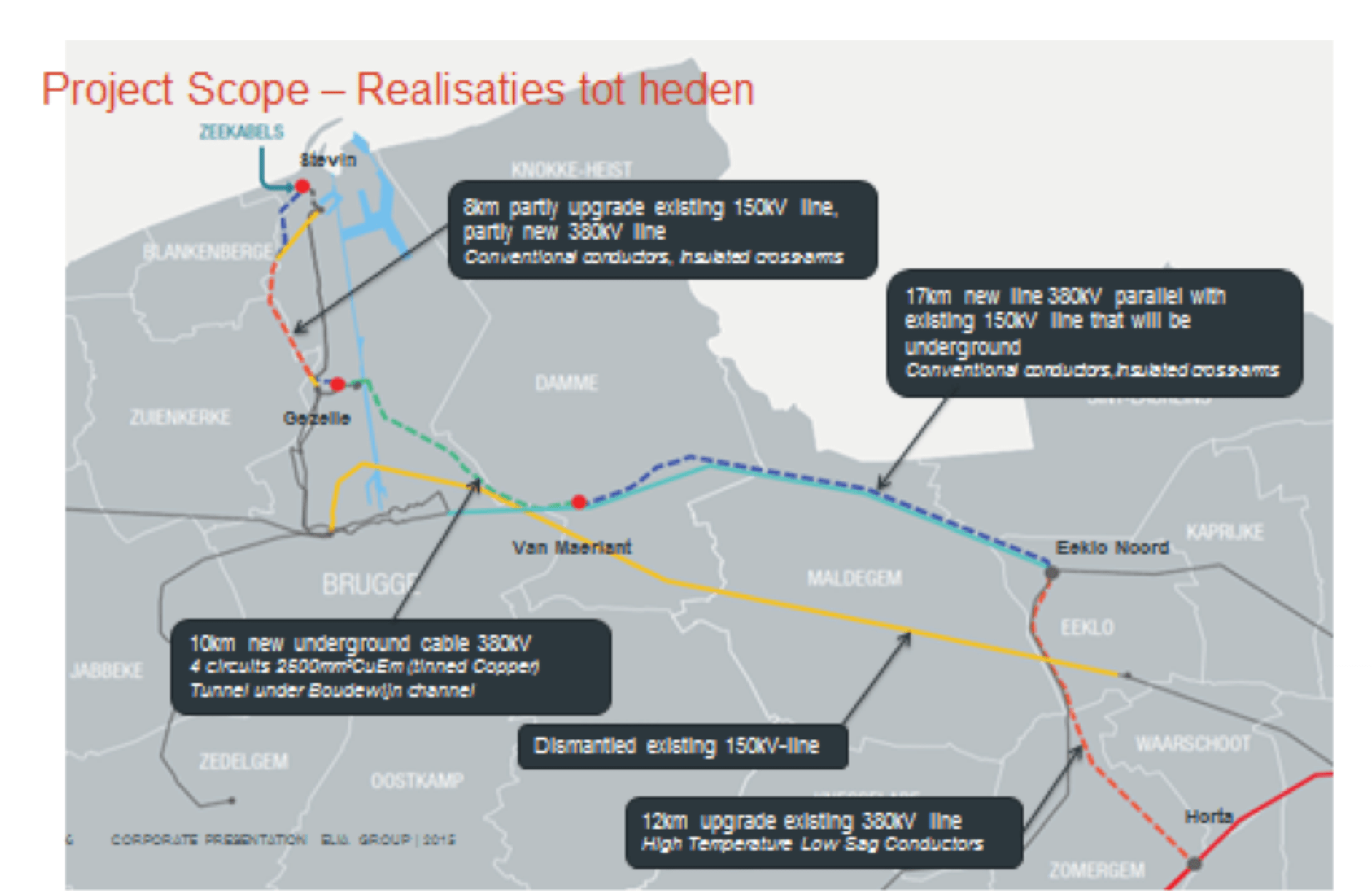
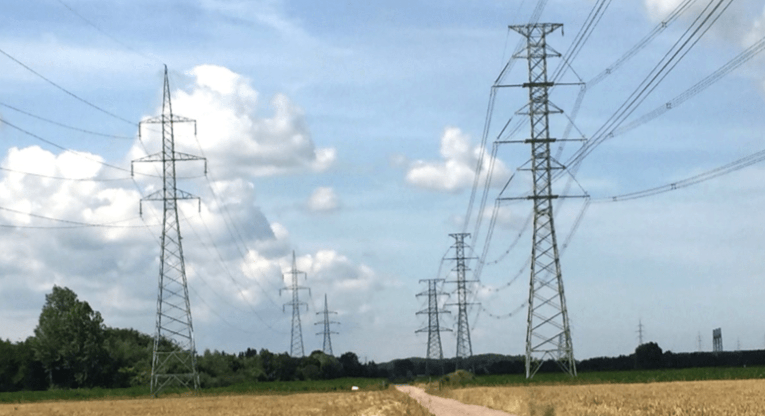
The existing 150 kV grid in the coastal region of Belgium was deemed insufficient to meet future energy needs. As a result, the Stevin Project had the goal of creating a new 380 kV connection between the coast and Elia’s existing 380 kV backbone grid. It addressed several key needs, of which connection to growing offshore wind generation in the North Sea (up to 2200 MW) and a new interconnection capability (1000 MW) with the U.K. were among the most important. A high diversity of technical and innovative solutions – such as a compact line with insulated cross-arms – were seen as necessary to promote public acceptance and facilitate obtaining the necessary permits to realize the project.
transporting about 10 times more electricity.

Design & Testing Insulated Cross-Arms
Application of this relatively new technology, i.e. a compact line based on composite insulated cross-arms, resulted in a comprehensive project that included a number of distinct phases:
• Development of proper specifications;
• Analysis of proposals for the tender;
• Quality control of manufacturers;
• Evaluation of different designs from the viewpoint of maximum permissible E-field;
• Type testing according to specifications;
• Development of new test methods and verification of complete design;
• Demonstration & construction
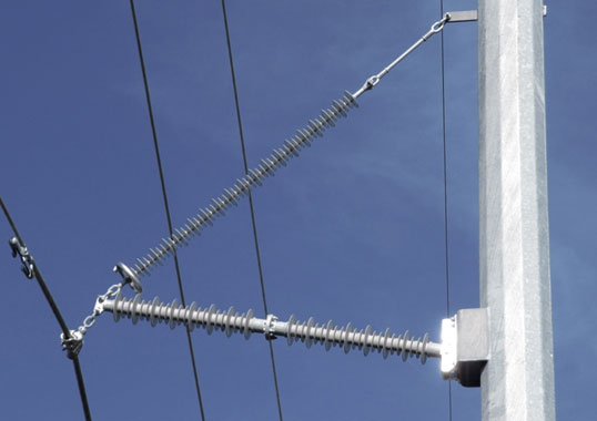
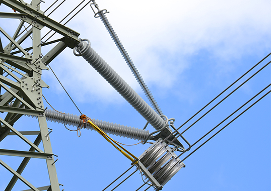
In order to maintain as much of the existing tower silhouettes as possible on complete sections and also to be able to withstand high compression loads, Elia decided to employ pivoting Vees (PV) for tangent towers (up to 3 gon running angle) and a non-pivoting Vee (NPV) design for small running angles of < 10 gon.
Application of NPVs was also used to limit section lengths with PVs in order to avoid stability risks, according to the IEEE guide.
Building the Compact Line
To build new compact lines within the framework of the Stevin Project, four contractors were selected. Initially, the work was perceived as highly challenging since it required completely new cross-arms erected with innovative work methods and tools. Only one of these contractors already had related experience with this kind of construction, used in the past in Italy.
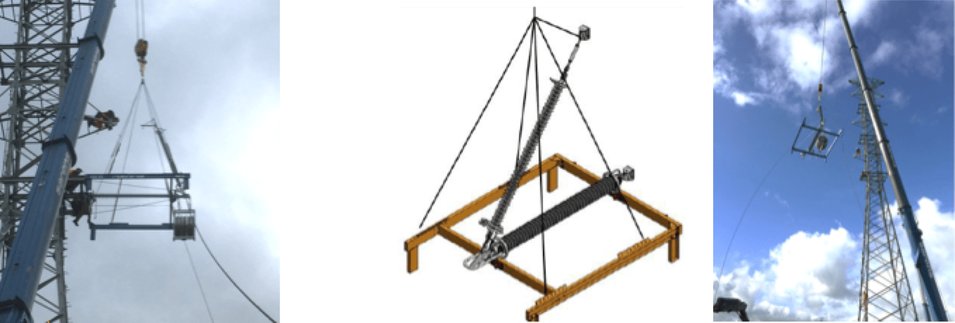
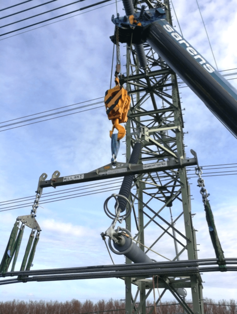
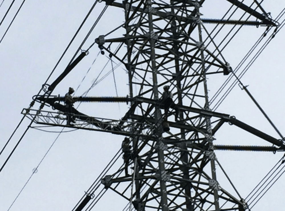
One contractor, for example, developed a flexible mounting platform that fits both the pivoting and non-pivoting cross-arms from both selected suppliers. This safe method initially required some adaptations that resulted in quicker installation time and eventually three cross-arms could be erected per hour. That covered one structure in about half a day, taking into account the time needed to shift from tower to tower. Two other contractors proposed attaching the insulated cross-arms directly to tower sections on the ground so as to be able to erect each level in a single movement. This was seen as more efficient but required greater focus on safety and co-ordination at ground level. It was also regarded as riskier in terms of the potential for damaging the composite insulators. The work method chosen also depended on delivery planning of the different components, from towers to insulated cross-arms.
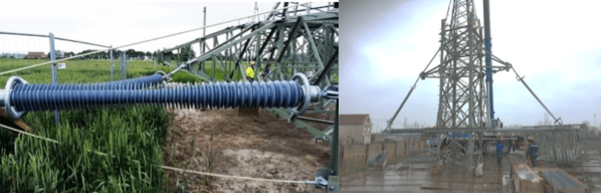
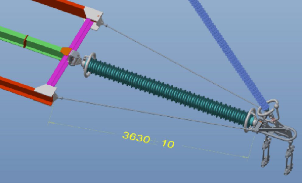
To avoid pivoting of the cross-arms during pulling operations, a blocking system made of guy insulators without silicone housings was developed and proved efficient. Even through there were risks in manipulating unprotected guy insulators (e.g. gloves were requested), this was seen as a better means of ensuring that there was no damage to the core and that it could fulfill the requirements. This would not otherwise have been possible.
Lessons Learned
By using both types of insulated cross-arms, i.e. pivoting vee and non-pivoting vee, some lessons were learned during installation of both types.
Pivoting Vee
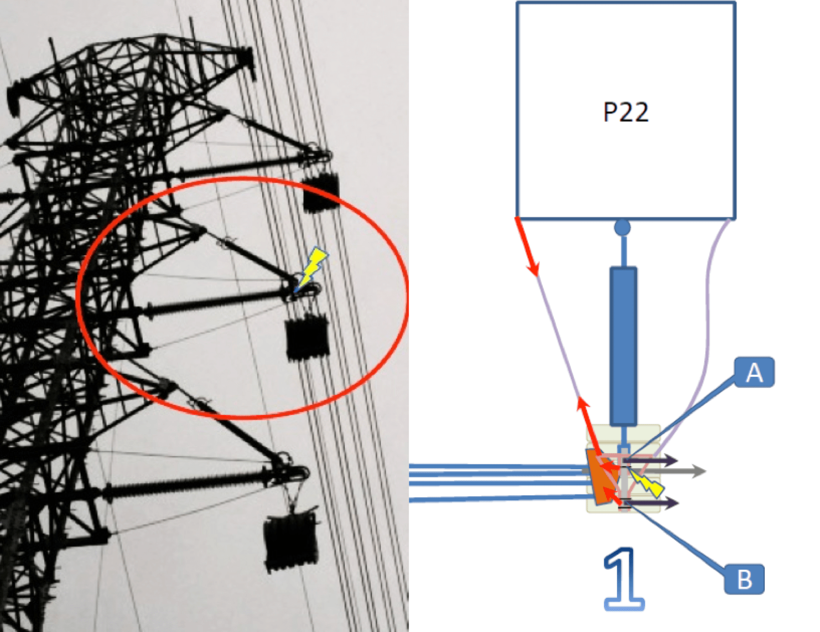
There was one incident, for example, with the blocking system during pulling operations. The pulling yoke had blocked in the pulley and caused a balancing problem. Given too high a force applied to the left guy insulator and its connection to the pivoting vee yoke, this caused failure. For safety reasons, the pivoting vee was therefore replaced with a new blocking system. From this experience, it was deemed advisable to work with only one safe short hanging point for the pulley in order to allow it greater freedom. It was also considered important to slow pulling speed when passing the pulley and to use only one pulling machine for the 4-bundle conductor.
A special clamping method was also used since there was no metallic fixed point to hoist conductors. This was combined with use of bucket trucks for workers to access the conductors.
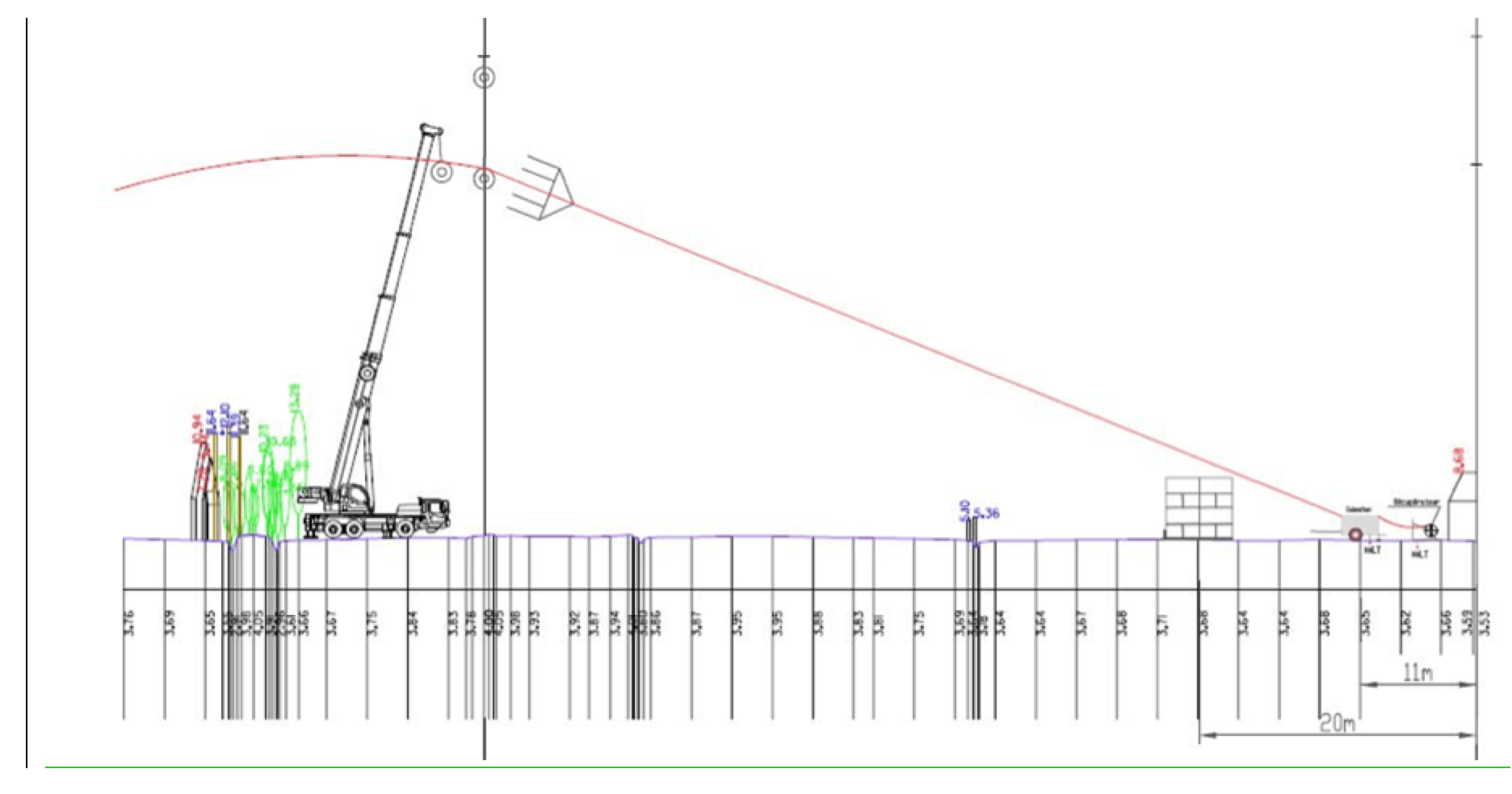
Normally, it was not allowed to put a pulling machine just after a pivoting vee but rather only after a dead-end tower. Due to some difficulty at one location, another work method was tested that appeared satisfactory although not ideal. This saw a crane used not only to limit vertical force but also any longitudinal imbalance on the pivoting vee.
Non-Pivoting Vee
This type of configuration had been foreseen for small running angles (< 10 gon) but clamping the conductors proved challenging due to swinging of the pulley. This required pulling the pulley from ground level and into a vertical position before starting to get the conductors out of the pulleys and clamping them. For an upcoming similar project named Brabo, a running angle up to 15 gon will be used. This will require special work methods with adapted tools still under development since pulling the pulley up from the ground will not always be possible.

Maintenance Needs
This was among the first questions posed by maintenance teams. Therefore, they had a representative in the original working group established to address all questions from the field. Development of a suitable access workbench was a part of the project as well as adapting some towers at Elia’s training centre in order to conduct pre-testing. Being able to install prototypes of cross-arms in a safe environment without time pressure as well as performing some tests with prototypes of the workbench were seen as musts. Adjusting work procedures to take into account all possible maintenance interventions on such a tower required meetings with competent staff. Moreover, 3D drawings were used to simulate all possible maintenance needs for these complex structures.
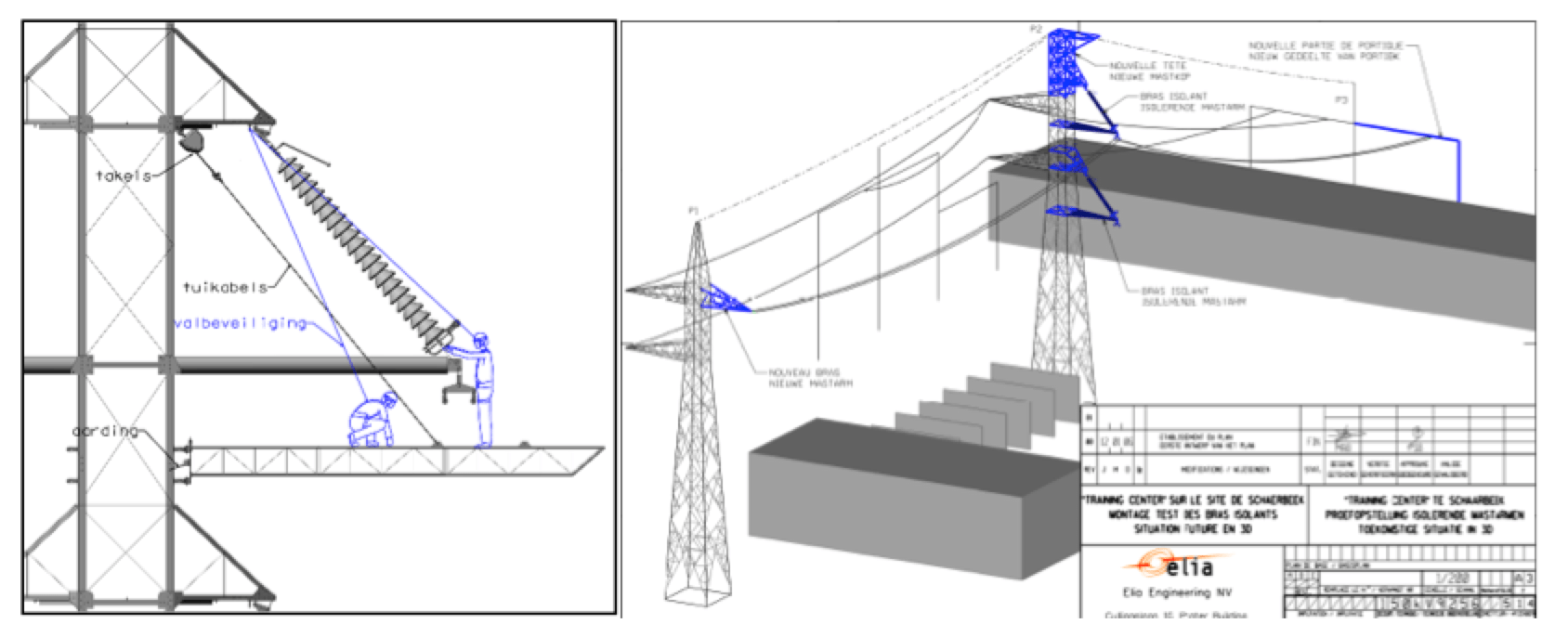
Having the possibility to access the ends of cross-arms without heavy trucks or cranes was seen as mandatory since not every tower is easily accessible from a road. The final workbench was developed with an external supplier and took some time to realize an optimal design that could be mastered quickly by field crews. Final tests with this prototype took place several months before construction on site and in the end minor adaptations were needed before delivery of work benches.
Composite insulators are still relatively new in Belgium and it therefore also became Elia’s responsibility to provide contractors with information regarding proper handling in order to avoid risk of damage during various operations. As such, Elia included in their specification that supply of handling and assembly instructions must be part of the order such that suppliers provide guidelines to all contractors. Cigre’s composite insulator handling Guide is still used as a reference and has recently been reviewed by WG B2.57. Along with other TSOs, Elia has also sponsored a document from STRI that gives clear guidelines for handling composite insulators.

Inspection
Having proper inspection procedures is one of the main challenges whenever introducing a new technology into the grid. Up to now, one of the main disadvantages of composite insulators is uncertainty in regard to how best to inspect them, with what frequency and with which types of devices. Firstly, Elia has asked suppliers to provide a 10-year guarantee for their composite insulators. Secondly, suppliers must deliver instructions and guidelines during the so-called ‘maintenance-free’ period as well as suggestions on which measures to apply after expiry of this period. Since not all suppliers are completely familiar with these issues, Elia participated in a project with other utilities, coordinated by STRI, with the goal of delivering proper inspection guidelines as well as documentation on any damaged composite insulators detected. This will then offer a solid base for future field inspection performed by Elia’s maintenance teams.
Conclusions
The two circuits of the compact line between Eeklo Noord and Van Maerlandt were successfully energized in June 2017 and this marked the end of a long journey. Elia encourages innovation but keeps a focus on ensuring the same level of reliability for the public as well as guaranteeing safety of its staff and contractors. Internal expertise may not always be sufficient in each area. Therefore reliance on numerous industry connections as well as on expertise of contractors can contribute to safe and efficient installation methods. For these kinds of complex transmission structures, simulation and testing are key to achieving the mechanical and electrical performance expected over the long-term as well as a safe operation and maintenance. Moreover, from the start this type of project requires good internal communications as well as close collaboration between different departments.