As demand for reliable power continues to grow worldwide, improving the lightning reliability of distribution systems becomes more and more common. Jonathan Woodworth, Chair IEEE WG 3.3.11 (Standard C62.11) and Co-Chair of IEC TC37 MT4 (Standard 60099-4,6,8) reviews options to improve system reliability through optimized application of surge arresters. Most examples discussed are from systems found in the U.S. and Canada but are also equally applicable to any system.
In North America, distribution systems are often of the 4-wire configuration with three phase conductors and one neutral. The neutrals are typically grounded at equipment locations. For systems located in high lightning regions, the neutral is also grounded where line arresters are installed. The most common distribution system configurations are 4-wire solidly grounded and three-wire grounded at the source only.
Best Practice 1: Tank Mounted Arrester
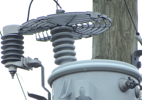
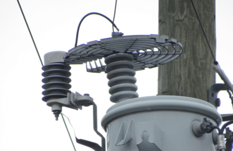
Protecting distribution transformers is nearly a universal application and Fig. 1 shows the most common configuration used. In this example, several best practices (BP) can be observed. BP1 is installation of the arresters directly on the can of the transformer. The benefits of this configuration include:
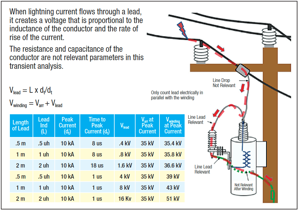
1. Shortest possible line leads achievable on a distribution transformer results in least degradation to protection offered by arrester (Fig. 3);
2. Arrester ground is part of steel tank and bracket holding arrester;
3. Arrester can come pre-installed on transformer with no extra installation cost;
4. Configuration is compact with no long conductors to be managed.
Best Practice 2: Wildlife Protection
Also shown in Fig. 1 is BP2, namely proper wildlife protection. In this case both the transformer and the arresters are properly protected to reduce the risk of a fault due to wildlife. Two important aspects are:
1. Wildlife guard is large enough to completely encompass critical flash points around top of arrester;
2. Connection lead enters top of arresters and bushings to minimize possibility of touch by wildlife standing on earth, e.g. can of transformer.
The rationale for a wildlife protector to be part of best practices for lightning protection is that anything that makes arresters more effective is in fact also making lightning protection more reliable.
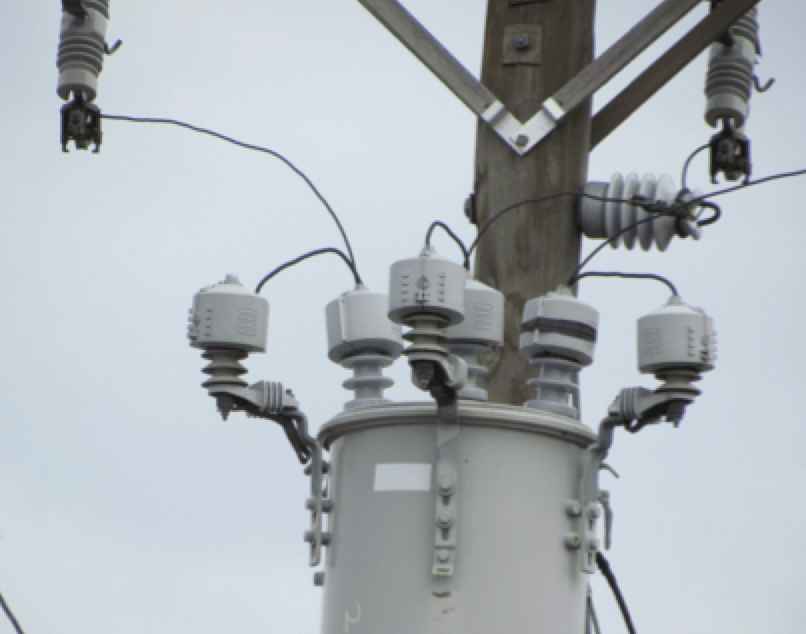
Fig. 2 is another example of BP2 with a wildlife guard that is effective on either arresters or transformer bushings. The dish style guard is easy to install and keeps all sizes of animals away from shorting the top of the arrester to earth.
CLICK TO ENLARGE
CLICK TO ENLARGE
Best Practice 3: Polymer-Housed Arresters
Polymer-housed units have dominated sales of distribution arresters since the early 1990s. Nevertheless, there are still millions of porcelain-housed arresters still in service. Using polymer-housed arresters is considered best practice due to superior safety. During an overload situation, a porcelain housed arrester has high likelihood of shattering and sending high velocity shards in all directions and over a wide area. By contrast, overload of a polymer-housed arrester has high probability of not fragmenting or expelling any parts, thus making it much safer.
Best Practice 4: Virtual Shield with Arresters
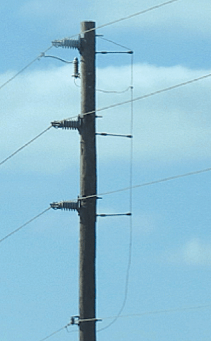
Fig. 4 shows a distribution system with a virtual shield wire. On this 25 kV system, the top phase is arrester protected, which means thet the top phase insulators will never flashover from a lightning surge. Because this is a vertical configuration, the top phase shields the two lower phases from direct lightning strikes. On the right side of the pole, fiberglass standoff insulators keep the arrester down ground wire about 0.4 meters from the pole. Per IEEE 1410 (no IEC equivalent as yet), this standoff insulator adds about 200 kV critical flashover voltage (CFO) to existing insulators, rated at about 160 kV CFO. With this configuration, the top phase has infinite CFO (less the reliability of the arrester) while the bottom two phases have about 360 kV CFO. A CFO of this level means two things: first, this installation is essentially immune to flashover from a nearby strike; second, the probability of a backflash during a direct strike is nearly zero. Ground resistance of the pole is important in this example but, if kept below 25 ohms, the backflash probability is extremely low. With addition of one arrester at the top of each pole and isolating the down ground with 200 kV, this system is virtually lightning proof. Unfortunately, this scheme does not work for horizontal configurations unless the center phase is higher (0.75 m to 1 m) than the two outside phases.
Installing Arresters Every 4-5 Spans to Increase Reliability
There is a false rule of thumb used on distribution systems that dates back many years. Essentially, it states that if arresters are placed on each phase at about every 4 -5 spans, this will reduce the line’s lightning outage rate. This is true. But it will only improve flashover rate of nearby indirect strikes and will have no effect on direct strikes. Unfortunately, direct strike flashover rate is much higher than indirect strike flashover rate on all distribution systems. This means that only a small reliability increase can be achieved using this dubious thinking.
Best Practice 5: Preventing Backflash on Underbuilt Lines
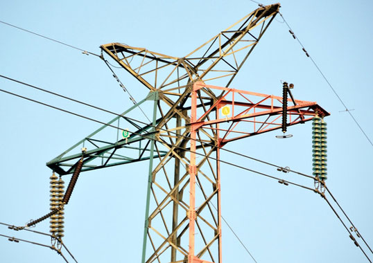
In the example shown in Fig. 5, each phase of each circuit is arrester protected. In a high ground flash density area, tall structures have a much higher lightning collection rate than shorter towers. By putting a distribution line on a tall tower, the lower voltage line will have a much higher risk of backflash from tower to phase during each high voltage line strike. This is true whether the high voltage line is well shielded or not.
Backflash is the phenomenon where, during a lightning strike, voltage at the pole end of distribution insulators increases by many kV. This voltage rise at the base of the insulators can increase to levels high enough to flashover the insulator backwards, i.e. from tower to phase. After the lightning backflash, a power frequency fault occurs causing an undesired momentary system outage.
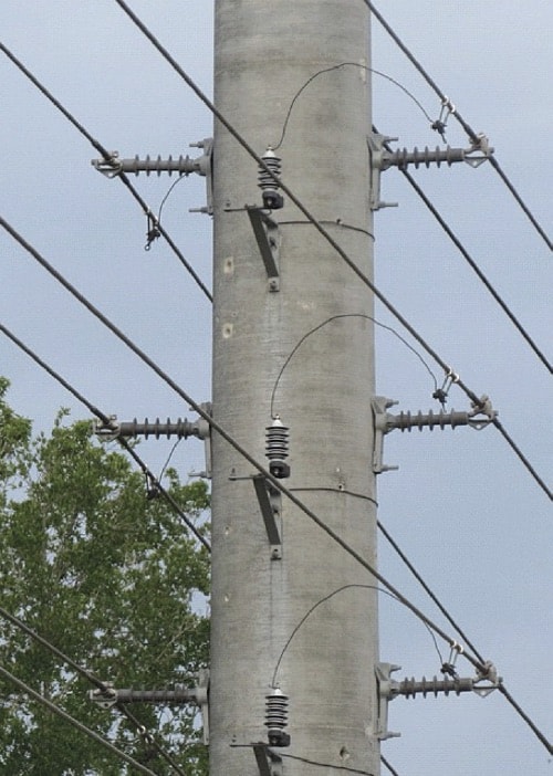
transmission line.
Best Practice 6: Surge Capacitors & Arresters on Generator Terminals
Power system generators often have 500 V to 15 kV output voltages and are usually far enough from lightning induced traveling waves that they do not need to be protected from that source. But there are often generator breakers in the circuit. If a breaker ages or malfunctions, a fast rising switching surge can make its way to the generator terminals. Generators are notoriously low in surge withstand and the consequence of a failure is so severe that application of a surge pack (Arrester-Cap Combo as shown in Fig. 6) seems a good choice. In this photo, a simple 3-phase capacitor and three separate arresters are used to make the generator 100% surge proof.
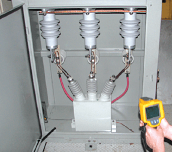
protecting generators.
Best Practice 7: Riser Pole Arresters
Use of arresters at junction poles between overhead and underground circuits is nearly universal – for good reason. Since cable is made up of non-recoverable insulation, this means that if it punctures it will not regain its insulating properties without attention. This is different from air insulators that recover insulating properties after a disruptive discharge around the insulator. Because the consequence of cable failure is so high, the practice of applying arresters where possible to protect the cable is important. Another aspect of this best practice is to keep lead wires above and below the arrester as short as possible. As seen in Fig. 7, the line and ground leads are very short. An important consideration for underground circuits is the impact of traveling waves on the end point of the circuit. When lightning strikes a system, the surge it creates does not appear over the entire circuit at the same time. Instead, it travels in all directions at nearly the speed of light. This traveling phenomenon results in significant voltage rises at points in the circuit where it hits a dead end or open point. At these locations, the surge travels to the end point and is reflected back from where it came. During the reflection event, the reflected voltage and parts of the incoming surge add together, thereby creating a voltage peak that can be double the initial voltage. Because of this voltage doubling phenomenon, using the best protection possible at the riser pole can be extremely important. For solidly grounded circuits, the ratings of a standard arrester can work well at the riser pole. But for delta and impedance grounded systems, special arresters using the best possible internal MOV disks are used to offer ‘premium protection’.
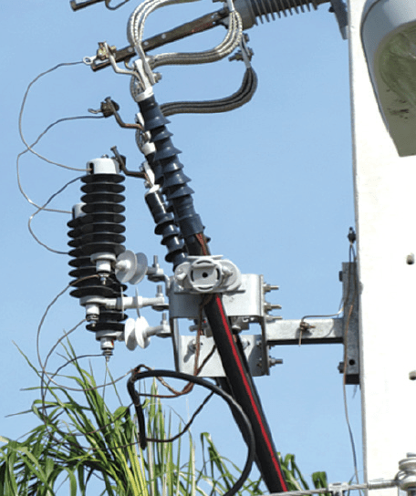
excellent lead length.
Best Practice 8: Open Point Protection
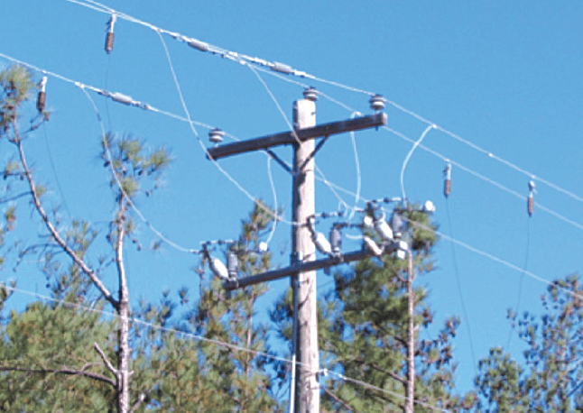
Traveling waves also occur on overhead circuits. When a surge reaches an open switch on a distribution circuit, it will double from the original value. If the surge is high enough, it will flashover the switch to ground. Fig. 8 is an example of open point protection. Since it is typically not possible to know from which direction the surge will arrive at the open point, arresters need to be installed on each side of the switch. Similarly, it is not possible to know which phase the surge will be on. As such, arresters need to be installed on each phase to make this practice effective.
Best Practice 9: Suspension Mounted Arresters
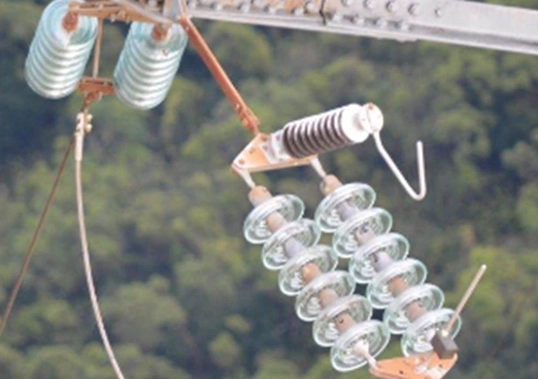
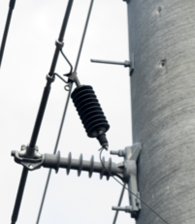
As shown in Fig. 9, modern day polymer housed arresters are light and can be suspended directly from distribution lines with no negative effect on the conductor. In this application, the arrester only needs to clamp the voltage at a level below the flashover of the line insulators. Therefore, lead lengths on the arrester are not that critical. This type of arrester is also more wildlife proof since there is no insulating bracket for an animal or bird to perch on and bridge the arrester.
CLICK TO ENLARGE
Best Practice 10: Double Protection from Breakers
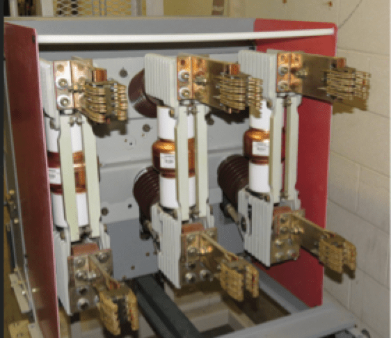
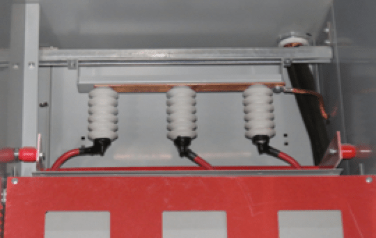
In distribution switchgear circuits, breakers are often close to other equipment. They are also known to produce very fast rising surges that can damage more sensitive equipment. To mitigate this risk, arresters must be applied on both sides of switchgear breakers.
CLICK TO ENLARGE
CLICK TO ENLARGE
Conclusions
There are many ways to protect distribution systems from the damaging effects of lightning, some better than others. It is indeed a never-ending battle to mitigate lightning.

