Japan has recently seen removal and replacement of XLPE cables with water barrier layers due to ageing. To evaluate effectiveness of these water barrier layers, pre-breakdown discharge detection tests were conducted on removed cables.
This edited contribution to INMR by Toshihiro Takahashi at the Central Research Institute of Electric Power Industry (CRIEPI) reports on investigations conducted into electrical insulation performance and its determinants for aged 66/77 kV XLPE cables de-commissioned from power grids based on pre-breakdown discharge detection testing. The report also examines the effectiveness of water barrier layers by comparing results with similar data from testing XLPE cables without such layers.


XLPE cables are used not only in underground power transmission and distribution systems but also in connections between apparatus (e.g. GIS, transformers, shunt reactors) and overhead lines. Installation of XLPE cables into Japanese MV and HV grids started around the late 1960s. Insofar as 66/77 kV, XLPE type cable (70kV) with short length was first introduced in Japan in 1964. Subsequently, adoption accelerated rapidly such that by the late 1980s, total installed length surpassed that of SCFF type cables. In fact, by the end of 2019, approximately 85% of 66/77 kV transmission cables in Japan were XLPE type
During the initial years (i.e. 60s and 70s), water-tree induced breakdown occurred frequently. Investigation identified water-treeing originating from minute foreign particles, voids, and moisture within the insulation as the cause of failure. Given this, improvements were made to the manufacturing process, including reducing presence of foreign particles in the cross-linked polyethylene during production and adopting dry curing to minimize presence of voids and moisture content.
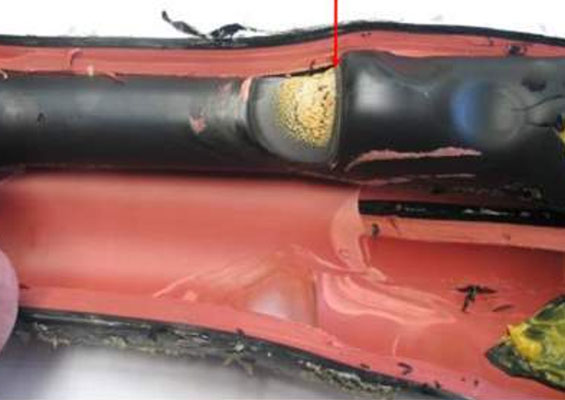
By the early 1980s, all XLPE cables were manufactured using the dry curing process. However, this did not eliminate water tree-induced insulation breakdown since 66/77 kV XLPE cables in Japan are often installed in underground ducts. In such cases, ducts usually fill with groundwater, meaning that cables must operate in a submerged or humid environment. Therefore, to reduce moisture penetrating through the cable sheath and reaching the insulation, a water barrier layer was developed. This design featured a lead or aluminum foil longitudinally attached to the cable core, followed by the sheath. Practical application of this technology began in the early 1980s and rapid installation across the entire power system followed.

Pre-Breakdown Discharge Detection Test
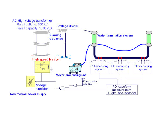
Fig. 1 shows the test facility developed by CRIEPI researchers. Breakdown tests are common to measure insulation performance of power equipment, including cables. However, when conducting these on cables, the breakdown point can become charred, making it impossible to distinguish the factors that govern insulation performance.
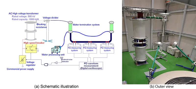
Since partial discharge (a precursor to breakdown) can occur just before breakdown, detecting partial discharge within the cable and stopping the applied voltage as soon as possible thereafter can prevent burning. This test method was developed in Japan during the late 1980s and is referred to as the ‘pre-breakdown discharge detection test’. Moreover, locating the point where partial discharge occurred and closely examining a slice of insulation from that location allows the factors that govern performance to be evaluated.

Defining Electrical Insulation Performance
In the pre-breakdown discharge detection test, high voltage AC is applied to the test cable using the step-up method and partial discharge is measured. Once partial discharge is detected, (called the ‘partial discharge inception voltage’) applied voltage must be stopped as quickly as possible using a high-speed breaker with semi-conducting devices.
This process is repeated to measure partial discharge signals precisely to localize their source until this is narrowed down to a section approx. 6 cm in the longitudinal direction of the cable specimen. Subsequently, insulation in this section is sliced into 0.5 mm thickness and stained.
Electrical trees develop in conjunction with occurrence of partial discharge. Therefore, searching for electrical trees and identifying the location where the extracted electrical tree development begins can serve as a determinant of electrical insulation performance. Hereafter, the applied voltage value when the partial discharge in the cable specimen first starts, divided by the insulation thickness at the electrical trees and the determinants, is treated as the breakdown strength and called ‘electrical insulation performance’ together with breakdown strength. If partial discharge occurs and voltage application is not interrupted, the partial discharge induces electrical tree development and quickly leads to breakdown.
During the pre-breakdown discharge detection test, it is not uncommon that breakdown does occur during testing either because the partial discharge signal was too small to detect or the partial discharge occurs in the termination outside the measurement range, and so on. Since the test cable is laid in underground ducts or tunnels, the most deteriorated point may be in the termination during pre-breakdown discharge testing. In this case, insulation breakdown can occur at the termination.
The outer semi-conducting layer at the cable end is removed to a length nearly equal to the length of the termination. This way, if breakdown occurs in the termination, it is necessary to separately handle breakdown at the location where the outer semi-conducting layer was removed and at the location where the outer-semiconducting layer remains. In the former case, electric field distribution at the termination is complex, making it difficult to accurately determine the electric field applied to the insulation at time of breakdown. Therefore, this data is considered invalid. In the latter case, if breakdown occurs at initial voltage application, breakdown strength (i.e. insulation performance) is obtained by the breakdown voltage divided by insulation thickness at the breakdown point.
By contrast, breakdown can also occur at a location where the outer semi-conducting layer remains during the process of obtaining the partial discharge signal in the cable body and repeatedly performing pre-breakdown discharge detection tests. Here, insulation performance is determined by the applied voltage observed when the partial discharge signal was first detected divided by insulation thickness at the thinnest point of the cable insulation.
If breakdown occurs in the cable body itself, and during the first application of voltage, breakdown electric field (namely electrical insulation performance) is defined as the breakdown voltage divided by the insulation thickness at the breakdown point. If partial discharge is measured during the initial energization and breakdown occurs during subsequent repeated pre-breakdown discharge tests, insulation performance is defined as applied voltage measured during the initial partial discharge divided by the insulation thickness at the breakdown point.
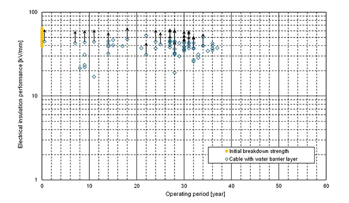
It is noteworthy that some cable specimens may have suppressed degradation and high electrical insulation performance, showing no breakdown, even at maximum voltage of the test equipment’s power supply and no measurable partial discharge. In such cases, maximum applied voltage divided by insulation thickness at the thinnest point of the cable insulation is treated as provisional insulation performance and indicated by a plot with an upward arrow on the corresponding graph.

Specifications of Cable Under Investigation
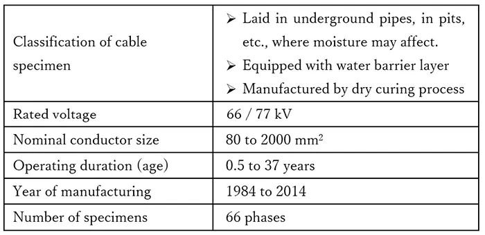
Table 1 shows specifications of the test samples in this research. Pre-breakdown discharge detection tests were conducted on 66 phases of 66/77 kV XLPE cables with water barrier layers, aged 0.5 to 37 years, with nominal conductor cross-sectional areas of 80 to 2000 mm² and not installed in tunnels, all of which were removed from service.
Insulation Performance of Aged XLPE Cables with Water Barrier Layer
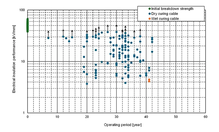
Fig. 2 shows the relationship between electrical insulation performance and operation period of 66/77 kV XLPE cable with water barrier layer. 4 phases of 66-phase cable specimens had breakdown at the position where the outer-semiconducting layer was peeled out in the termination, thus the effective data number is 62. As a result of the pre-breakdown discharge detection tests for the decommissioned 66/77 kV XLPE cables, breakdown occurred in 18 of the 62-phase cable specimens. No breakdown or partial discharge signal was observed in 24 specimens, which are shown in Fig. 2 with plots accompanying upward-pointing arrows. Note that the plots for age 0 years shown in the graph, i.e., the initial values, are calculated using the Weibull parameters for the breakdown strength of new XLPE cables as reported in the literature, with the same number of data points as the plots displayed. As can be seen from Fig. 2, many of the 66/77 kV XLPE cables with water barrier layers have very high electrical insulation performance, almost the same as for new XLPE cables. This means that deterioration of the 66/77 kV XLPE cable with water barrier layer was significantly suppressed. Fig. 3 shows the relationship between insulation performance and operation period of 66/77 kV XLPE cable without water barrier layer, namely wet design cable as shown in the literature. Comparing Figs. 2 and 3, it becomes clear that the water barrier layer is effective in suppressing deterioration for operation of 30 years and more.

Determinants of Insulation Performance of Aged XLPE Cables with Water Barrier Layer
As a result of the pre-breakdown discharge detection tests for the de-commissioned 66/77 kV XLPE cables, breakdown occurred in 18 of the 62-phase cable specimens. No breakdown or partial discharge signal was observed in 24 specimens. Among the remaining 20 samples, water trees were identified as the starting points for electrical trees in 13 cases, all of which were BTTs that did not reach either inner- or outer semi-conducting layers. In addition, things that could be considered as contaminants were observed as the starting points for electrical trees in 7 samples.
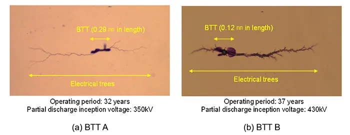
Fig. 4 shows examples of the determinants of insulation performance picked up after pre-breakdown discharge detection testing. These are all bow-tie type water trees (BTTs) with lengths of less than 0.3 mm. Some BTTs have contaminant-like cores at their initial points. It is difficult to analyze their chemical components because sizes are too small to analyze and are buried in XLPE. Still, researchers are trying to analyze these precisely. In 13 phases of examined 62-phase cable specimen, the determinants of insulation performance were BTTs.
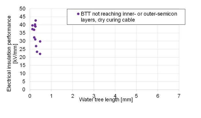
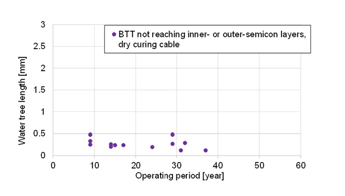
Fig. 5 shows the correlation between obtained BTT length and insulation performance. It seen that obtained BTT length is extremely short, maintaining high insulation performance high while exhibiting a range between 20 and 45 kV/mm. Detailed data, such as operating period, is available for every XLPE cable used in this research. As such, correlation between length of water trees as a determinant of insulation performance obtained in XLPE cables with a water barrier layer and the operational period was evaluated as in Fig. 5. It is evident that bow-tie tree length appears to be relatively unaffected by an increase in operating period. This can be because the water barrier layer prevents moisture from penetrating the insulation from outside the cable, thereby suppressing progression of water trees. However, since number of data points is insufficient, further data would be necessary.

Conclusions
This report presents the results of ageing analysis and identifying insulation performance determinants obtained from preliminary breakdown tests conducted on 66 phases of 66/77 kV de-commissioned XLPE cables with water-blocking layers (62 phases of which were valid samples).
The following findings were clarified:
1. Degradation in insulation performance due to aging was significantly suppressed;
2. Determinants of insulation performance were bow-tie type water tree (BTT) not in contact with inner- or outer-semi-conducting layers; however, in some cases, something that could be considered a contaminant determined the electrical insulation performance of the corresponding cable specimen;
3. No clear correlation was observed between length of BTT as determinant of insulation performance and operating period of the cable specimen.
Further study will be necessary to investigate whether identified determinants of electrical insulation performance contribute to degradation over time of cable operation.
References
[1] S. Yoshida: “Study on Systematic Development of Power Cable Technology”, Survey Reports on the Systemization of Technologies, Vol. 19, No. 80, Center of the History of Japanese Industrial Technology, National Museum of Nature and Science, Japan. (2013) (In Japanese)
[2] “Advanced Maintenance Strategies and Asset Management for Underground Transmission Cables”, Electric Technology Research Association Report Vol. 79, No. 1 (2023) (In Japanese)
[3] T. Takahashi, T. Kurihara, T. Takahashi, T. Okamoto: “Water tree Degradation on Long Term Operated 60 kV Class XLPE Cables Decommissioned from Actual Power Grid”, Jicable’19 – 10th International Conference on Insulated Power Cables”, Jicable’19 – 10th International Conference on Insulated Power Cables, No. E2-5 (2019)
[4] T. Takahashi, T. Kurihara and T. Okamoto: “Deterioration Characteristics of Electrical Insulation Performance for 60 kV Class Decommissioned XLPE Cable Manufactured Dry-curing Process”, IEEJ Transactions on Power and Energy, Vol. 140, No. 4, pp. 299-304 (2020) (In Japanese)
[5] T. Takahashi, T. Takahashi, T. Kuraishi, T. Okamoto, S. Tanaka, Y. Matsuya, T. Doi: “Remained Withstand voltage Level and Effect of Water Tree Degradation of Removed XLPE Transmission Cables with Long-term Operation”, International Conference on Condition Monitoring and Diagnosis 2010 (CMD2010), B2-3 (2010)
[6] T. Takahashi: “Insulation Capability & Degradation of Highly-aged XLPE Cables Decommissioned from Service on Power Grids”, INMR World congress 2023 (2023)
[7] T. Takahashi, et al.: “Effect of water barrier layers on insulating performance degradation for 66/77 kV XLPE cables through experimental investigation for those decommissioned from actual power grids”, Spring 2025 IEEE Meeting, A06D03 (2025)
[8] T. Endo: “A Study on Breakdown Triggers of XLPE Cable Insulation using Pre-Breakdown Discharge Detection Method”, IEEJ Transactions on Power and Energy, Vol. 108, No. 10, pp. 451-458 (1988) (In Japanese)
[9] “High voltage testing method on XLPE cables and accessories”, Electric Technology Research Association Report Vol. 51, No. 1 (1995) (In Japanese)