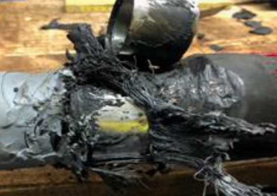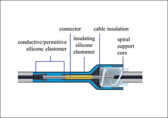
Self-supporting, fluid-filled terminations have been used since the advent of HV cables and continue to be the first choice among most network operators due to their excellent long-term performance. Recently, composite housings have increasingly replaced porcelain in such applications and also come to represent the state-of-the-art for these components. The basic design of the latest generation of fluid-filled terminations consists of a hollow core composite housing and a silicone rubber stress cone installed onto the cable insulation. The remaining volume is usually filled with a silicone oil compound, one of the most environmentally friendly choice among alternative insulation media. The main advantages of this design are its ease of application across a broad range of different cable sizes and types as well as its adaptability to the service environment and mechanical requirements of any installation. Although these types of terminations are usually reliable and safe, isolated cases of electrical breakdown can never be totally excluded. The worst-case failure mode results from a high temperature internal power arc that causes rapid vaporization and thermal expansion of the insulating medium. Due to sudden internal over-pressurization, the termination could easily explode, scattering debris and threatening collateral damage to nearby network equipment while also presenting a safety threat to the public. Given this, cable accessory manufacturers and users have tried to reduce risks by minimizing the consequences of such an event. The result has been development of explosion resistant terminations that provide a cost-effective and reliable solution in applications where terminations are sited in sensitive locations. Design and testing activities linked to this development were reported in this past INMR article contributed by Brugg Kabel in Switzerland.
Internal Power Arcs on Outdoor Terminations
During a power arc inside a termination, the electrical discharge channel in the form of plasma leads to rapid transition of the insulating medium from liquid to vapor. The result is a sudden increase in pressure of the vapor phase, generating shock waves that stress the entire construction. If these dynamic stresses surpass the maximum mechanical strength of any of the termination’s components (i.e. its hollow insulator housing, top and bottom flanges or the bolts that fasten it to the support structure), mechanical breakdown can occur. Debris can then be ejected at high velocity all around the installation. There are two possible options to address this problem. The first is to design a termination able to withstand even the high pressures developed during an internal electrical breakdown. This solution, however, would require costly over-engineering that would greatly restrict its economics and field of application. A more practical option is achieved through controlled release of the increased internal pressure during the early stages of a power arc. This would limit the maximum overpressure and resulting projection of any debris. To achieve this result, however, the termination would have to be equipped with embedded pressure release devices able to operate within only a few milliseconds of ignition of the internal arc.

Design of Pressure Release Devices
The main challenge during the development phase of this second option was designing a reliable pressure release device. For example, one of the limiting conditions was that the device would have to be capable of releasing the pressurized fluid within only 2 milliseconds after arc ignition, while also offering the mechanical strength needed for prolonged, safe service at normal operating pressures. A way of best integrating such pressure release devices into existing designs of composite-housed terminations also had to be found. In the end, this was achieved by placing the devices at the top (i.e. integrated into the corona shield) as well as at the bottom of the termination (i.e. integrated into the base plate).
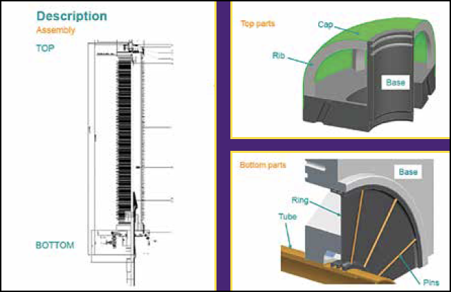
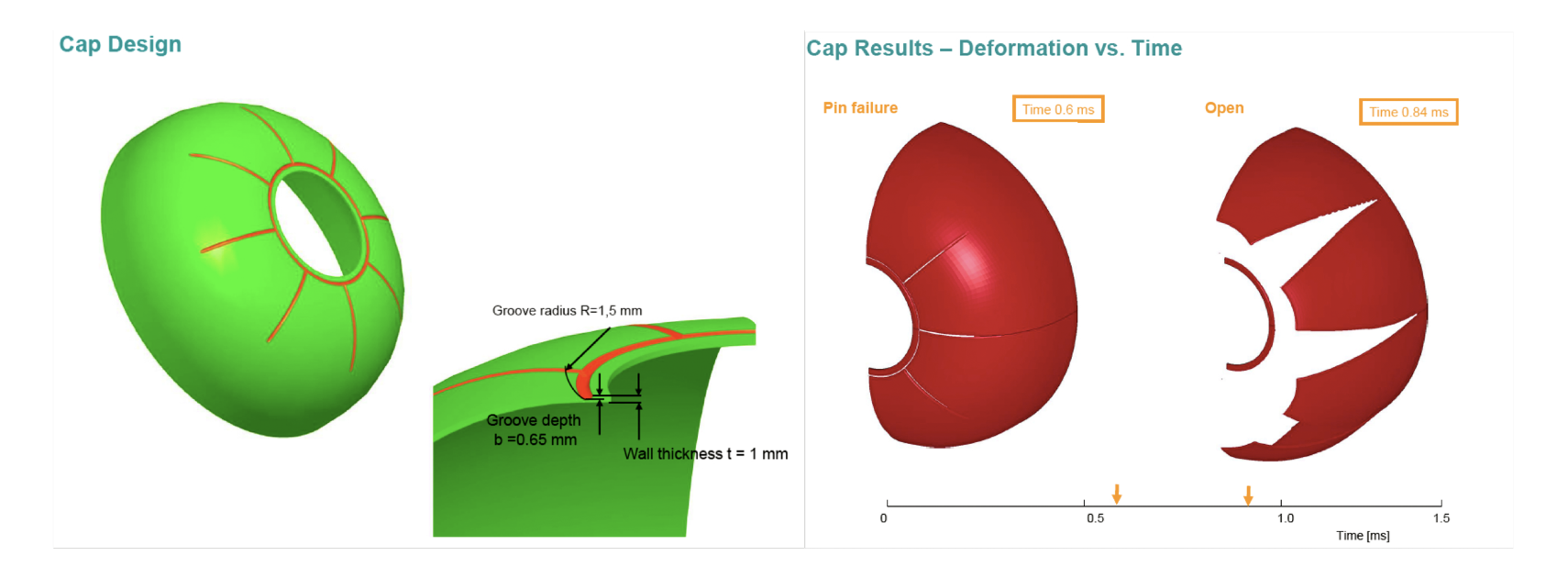
Although having different shapes, both devices are designed to act similarly upon a burst disc but with different dynamics. In order to minimize work devoted to experimentation with different concepts, which then took place only during final product development, the design phase relied heavily on finite element analysis. In order to also function as a corona shield, the pressure device at the top of the termination took the shape of a cap with 8 grooves that break at a predefined mechanical stress, allowing the cap to open like a tulip (see Fig. 2).
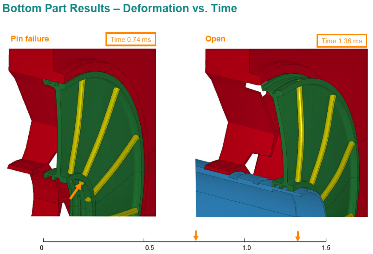
The pressure device placed at the bottom of the termination was integrated into the termination’s basic design and supported by pins fastened to its base plate, as shown in Fig. 3. Should a predefined pressure level be reached, the disc is expelled in an axial direction towards the bottom of the termination.

Type Test of 400 kV Termination
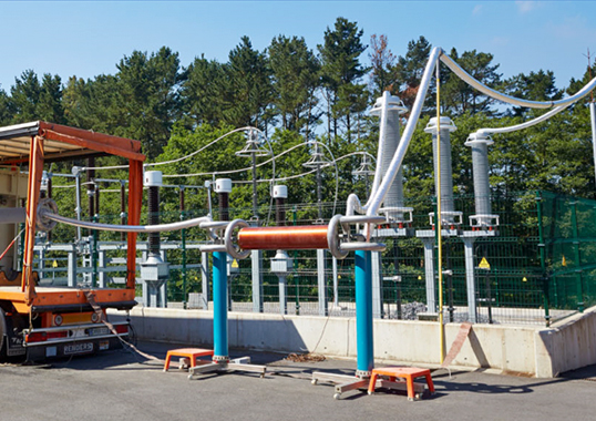
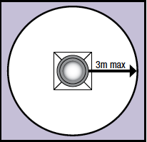
In order to be certified as resistant to the impact of internal power arcs, a cable termination for system voltages up to 150 kV has to be tested according to European standard HD 632:2008 S2, which stipulates that, upon completion, no debris can be found beyond 3 meters from the test object. Since no equivalent standard for higher voltages still exists, the same requirements and testing procedures can be adopted.
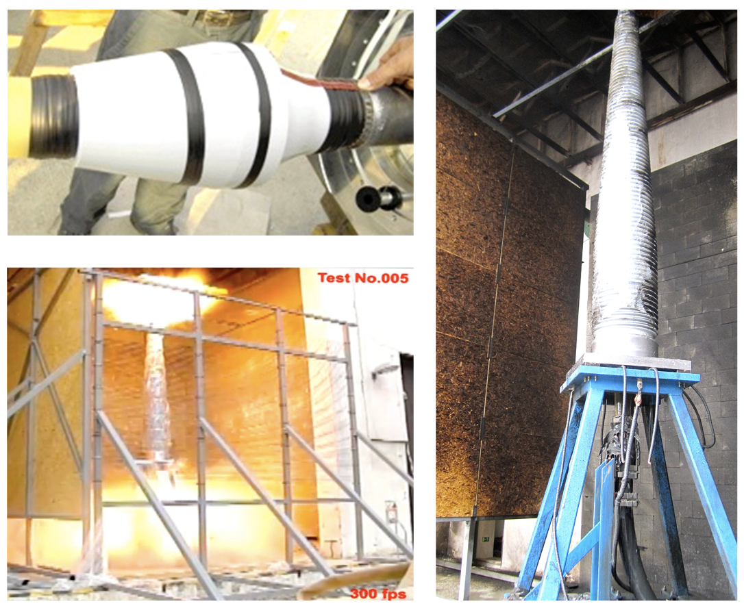
The internal arc test is conducted for duration of 0.5 seconds. It is performed in a single-phase test circuit with 20 kV supply voltage and a symmetrical 50 Hz short-circuit current of 63 kA, provided by a 2500 MVA power generator. To induce the internal power arc inside the termination, the test set-up consists of short-circuiting the cable conductor to the cable screen using a 1.5 mm2 copper wire prior to final assembly of the termination.

Field Installation
Installation of explosion-resistant outdoor terminations requires no special measures on-site, apart from reinforcing the support to counter the force following rapid release of oil. By following the unit’s basic modular configuration, this type of termination can be installed in basically the same manner as a conventional unit. Both pressure release devices are pre-assembled at the factory under strict quality control procedures prior to delivery. This serves to minimize any potential for error during installation in the field.
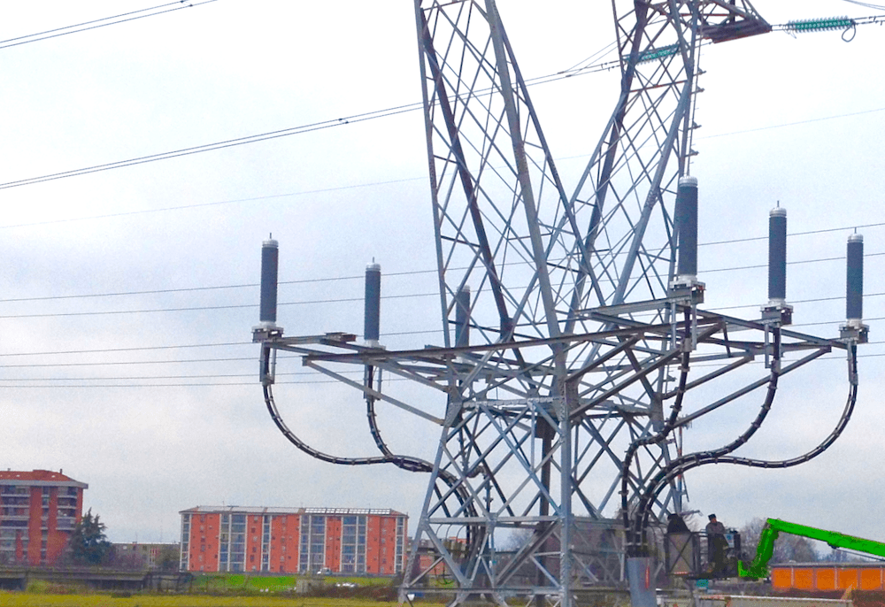
Market acceptance of this new safety design has been high. For example, shortly after release onto the market, some 20 units for 150 kV and over 50 units for 220 kV cable systems were installed by Italian grid operator, Terna. Demand for explosion-resistant outdoor terminations from Brugg Kabel has since increased significantly, with more than 120 installations annually for voltage systems up to 245 kV.
Conclusion
Integration of an overpressure release device into the usual design of composite outdoor terminations offers a solution to minimize risk of injury or collateral damage in the event of an internal arc in oil-filled outdoor terminations. Ease of installation and no special requirement for additional maintenance versus other terminations allow this product to be easily integrated as a standard component in any network. The only basic requirement is some reinforcement of the steel structure to counteract the pressure wave from an internal arc.