If one studies the evolution of composite insulator technology since its initial development during the 1970s, one fact quickly becomes clear: market experience for composite apparatus insulators has been much different than for composite line insulators. For example, composite insulators for overhead lines were received with great interest by power supply companies due to their promised advantages of superior pollution performance as well as light weight combined with high strength. However, much of the initial enthusiasm ‘evaporated’ once users became aware of the accompanying risk of mechanical failure and dropped conductor – a failure mode labeled brittle fracture that reached its peak during the 1990s. To some extent, mechanical fracture of the core rod is still encountered today, especially with older generations of line insulators or with units that have been damaged during handling or produced without proper quality control.
Nevertheless, after intensive research in the U.S. and China, most experts now believe that the cause of this problem is well understood and that modern composite line insulators are designed and manufactured to virtually eliminate such a risk. Composite hollow core insulators, on the other hand, never suffered from any documented mode of failure. In fact, service experience has, by and large, confirmed that this technology offers the high performance expected across most applications, assuming that the insulators were properly specified for their service environment.
For example, a survey was undertaken in recent years and involved close-up inspection of several dozen silicone rubber apparatus insulators from 145 to 420 kV AC and from 400 to 500 kV DC. These units had reportedly been in service for years across a range of different environments characterized by high humidity and/or UV as well as varying levels of pollution severity. According to the final report, no significant deterioration was observed nor had any lost hydrophobic properties, even to an intermediate degree. All still possessed a wettability class (WC) of at least 4 and typically much better, meaning good long-term hydrophobicity.
Still, in spite of positive field experience, the rate of application of composite hollow core insulators has until recent years proven much lower than for their ‘cousins’ operating on overhead lines. One of the reasons for this is that, unlike line insulators that are typically specified and purchased directly by the power companies or turnkey line contractors, equipment insulators are usually ordered by the OEMs of breakers and transformers, etc. For these types of customers, the main purchase considerations have always been cost as well as a guaranteed long service life. Here, competition from porcelain has proven challenging, especially at the lower transmission voltages where the greatest volumes are required.
Yet in spite of having lagged behind expectations for years, application of hollow core composite insulators is now growing rapidly – even exponentially. Driving this is a growing requirement for safety against risk of catastrophic failure by power utilities that, in many cases, now only accept equipment insulated with hollow core composite type insulators. While in 1993 less than 100,000 units were estimated to be in service, that population has soared and now numbers well over a million, with most installations taking place in just the past ten years.
After more than 30 years of field experience, composite insulators have become a mature technology and are widely regarded as a promising alternative to traditional ceramic insulators. In the case of overhead AC transmission lines, it is estimated that the population of composite insulators already in service numbers circa 20 million. When it comes to HV substation apparatus, it is estimated that more than a million composite housings are now in service and the trend seems to be toward exponential growth.
Composite insulators have been widely adopted for DC applications as well, however service experience here is much less due mainly to the relatively low number of DC lines and substations compared to AC. Nevertheless, exponential growth is foreseen in DC too due to the recognized advantages of superior performance under pollution, lightweight and safety in the event of explosive failure.
CLICK TO ENLARGE
CLICK TO ENLARGE
There are two broad yet complementary approaches used when collecting and analyzing service experience for any new type of electrical equipment or network component. The first is based on general experience and the output here includes numbers of units installed, average or maximum service life and, if possible, some estimate of reliability as well. The second approach, by contrast, involves a close-up investigation. Here, selected in-service components operating for a long period in different specific environments or installed for many years at test stations are carefully inspected.
[inline_ad_1]
According to the first approach, it can be said that the overall service experience with the latest generation of composite line and apparatus insulators is satisfactory both from the pollution performance and ageing points of view. For example, a recent CIGRE Brochure indicates that the reliability of modern composite line insulators is about the same as for glass insulators.
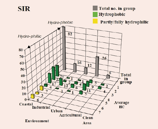
One of the first efforts toward a close-up investigation was conducted by STRI between 1994 and 1998. In-service inspections were carried out by 36 power utilities on 279 composite line insulators and these findings were complemented by results from test stations. To allow proper comparison of the insulators removed and inspected from different sites, a Guide (similar to guides presently offered by EPRI and CIGRE) was developed showing typical examples of deterioration and damage reported on composite line insulators. One such analysis is presented in Fig. 1.
CLICK TO ENLARGE
Based on this visual inspection of composite insulators installed at long-term test stations as well as in-service, the main conclusion at the time was that whatever deterioration was observed was more likely associated with design and/or manufacturing problems rather than ageing of the material. This turned out to be an important finding and supported continued development and application of composite insulator technology.
More recently, ABB undertook a general review of service experience with 110,000 of its silicone rubber apparatus insulators and the findings, summarized in 2011, were uniformly positive. The first attempt at a close-up investigation for these insulators, however, was based only on results from certain test stations. These included two coastal test sites (Kelso in South Africa and Dungeness in the U.K.) and one clean inland site at STRI in Sweden. The results supported continued application of composite insulators and could be summarized as follows:
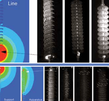
1. No deterioration of silicone rubber insulated apparatus was observed, either in clean or in polluted environments. Moreover, the superior performance (i.e. less ageing) of these units in comparison with silicone line insulators also installed at these same sites was attributed to differences in levels and distribution of E-field (see Fig. 2).
CLICK TO ENLARGE
2. The specific creepage distance of composite insulators could be reduced, in comparison with porcelain insulators, without sacrificing service performance.
CLICK TO ENLARGE
Given the above, ABB recently undertook and completed a close-up, detailed investigation into real field experience with composite-insulated apparatus. The specific design in this case involved the company’s helical profile sheds made from HTV silicone rubber while the locations of greatest interest included severely polluted service conditions.
CLICK TO ENLARGE
Site Selection for Close-Up Investigation
A total of 11 sites of specific interest were selected based on local service conditions and the following criteria:
• Relatively long time in service (ideally at least 5 years);
• Diverse heavily-polluted environments (e.g. deserts, industrial, coastal) preferably combined with high UV radiation levels;
• Less polluted environments (e.g. inland) but with low temperatures as well as frequent rain;
• AC and DC voltage applications.
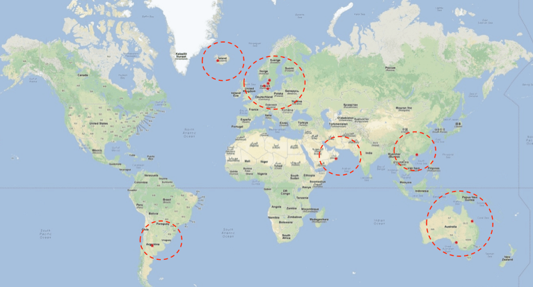
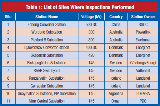
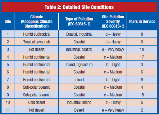
This resulted in selection of substations to be investigated in 7 countries: Argentina, Australia, China, Iceland, Denmark, Oman and Sweden. Priority was given to AC installations, however some DC installations were also included. The inspections eventually covered sites with all of the five different environments defined in IEC 60815-1, i.e. desert, coastal, industrial, agricultural and inland.
[inline_ad_2]
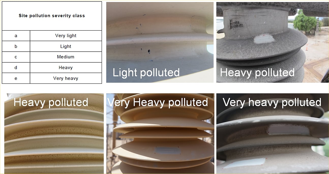
More than 50% of the climates eventually studied were humid according to the definitions in the Koeppens climate classification – one of the most widely used. About half of the sites were in areas with heavy to very heavy Site Pollution Severity (SPS), according to IEC 60815-1. Moreover, 4 sites were located in areas with high levels of UV radiation (i.e. Argentina, Australia and Oman) but below an altitude of 1000 m.
The apparatus insulators inspected at these sites represented a range of voltage classes from 145 kV to 420 kV AC and from 400 kV to 500 kV DC. The total operating time of these insulators varied from 2 to 17 years.
Inspection Procedure & Results
A standard form of data collection was developed and included data on climate and environment at the inspection site as well as existing service experience with standard porcelain-housed equipment (where available). The inspection procedure included: careful, close visual inspection with photography; ESDD/NSDD measurements according to IEC 60815-1 (ESDD measurements were performed directly on composite apparatus insulators according to the latest CIGRE Brochure, i.e. average values were weighted for different parts of the insulators); hydrophobicity measurements were done according to IEC 62073 with measurements of Wettability Class (WC).
[inline_ad_3]
Results of Visual Inspections
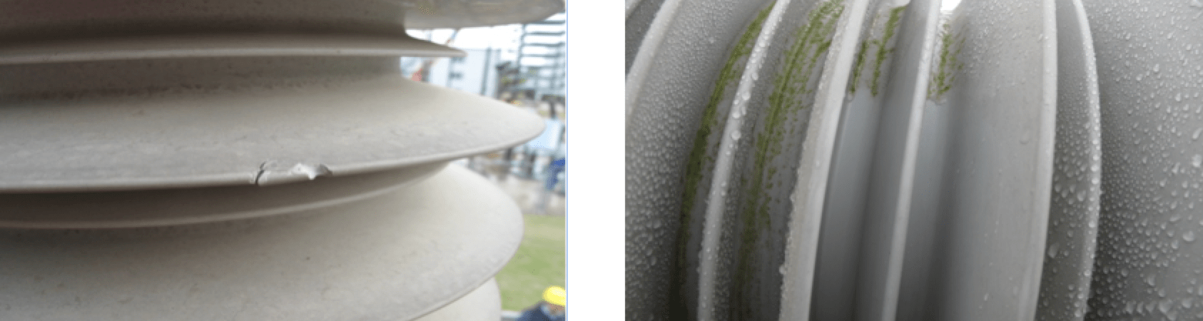
A total of 58 insulators at 11 sites were inspected using the special STRI Guide for assessing deterioration and damage to apparatus insulators. Most were in good condition, with no observable deterioration, although a few minor surface marks were found e.g. mechanically-induced, although such marks will not influence safe operation. In regard to biological growth which has also been observed, it has been shown that algae do not feed on silicone rubber and are only a surface phenomenon. Moreover, past researchers have concluded: “The risk for flashover due to biological growth is rather low because in order to lead to flashover, the resistance of the pollution layer should be relatively low. However, biological growth normally occurs in relatively clean areas leading to a situation where either the insulator will be hydrophilic, but clean, i.e. with high resistance, or it will be contaminated but free of biological growths and therefore hydrophobic (due to recovery of hydrophobicity) with high resistance”.
CLICK TO ENLARGE
CLICK TO ENLARGE
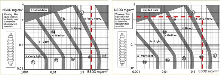
Results of Pollution Measurements (ESDD/NSDD)
Pollution was sampled from small areas (about 12 cm2) in different locations along insulators being assessed. Typical areas used were the top larger diameter shed, the bottom larger shed, a trunk larger shed, and similar for smaller diameter sheds. It should be noted that a stochastic single collection of ESDD and NSDD samples is not sufficient to estimate site pollution severity (SPS).
According to IEC 60815-1, ESDD/ NSDD measurements for estimating SPS must be performed on ‘standard’ ceramic insulators and at least over a period of one year, following the special procedure. A single measurement of ESDD and NSDD performed on composite apparatus insulators is therefore only a rough estimation of their pollution state on that particular day. Moreover, the pollution state of the insulator will vary over time, depending on a number of factors, e.g. wind, rain and season.
CLICK TO ENLARGE
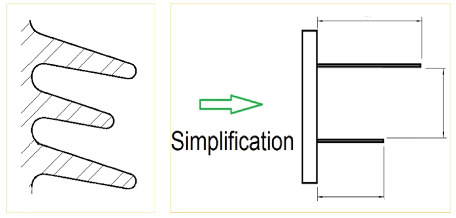
In order to obtain average ESDD/ NSDD levels from small sampling measurements, as in this case, it is necessary to estimate the percentage of the entire insulator that corresponds to each typical measurement zone so as to make a weight-corrected calculation. The trunk area, for example, is a small part of the whole insulator compared with the large top shed area.
CLICK TO ENLARGE
CLICK TO ENLARGE
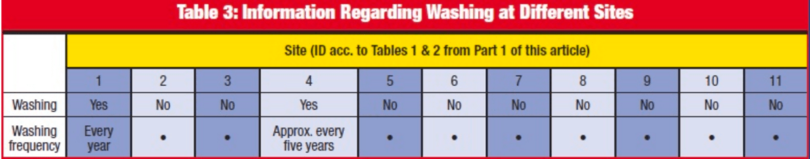
At the same time, it is noteworthy that some insulators inspected were exposed to regular cleaning by the user utilities – a procedure not really needed and in fact not recommended by the manufacturer. If the insulator is washed regularly (e.g. from once a year to once every few years) the level of ‘instantlymeasured’ ESDD and NSDD might be lower. For this reason, it was seen as beneficial to collect past washing data from end users.
[inline_ad_4]
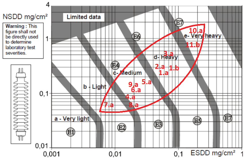
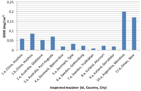
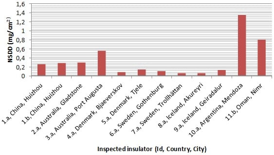
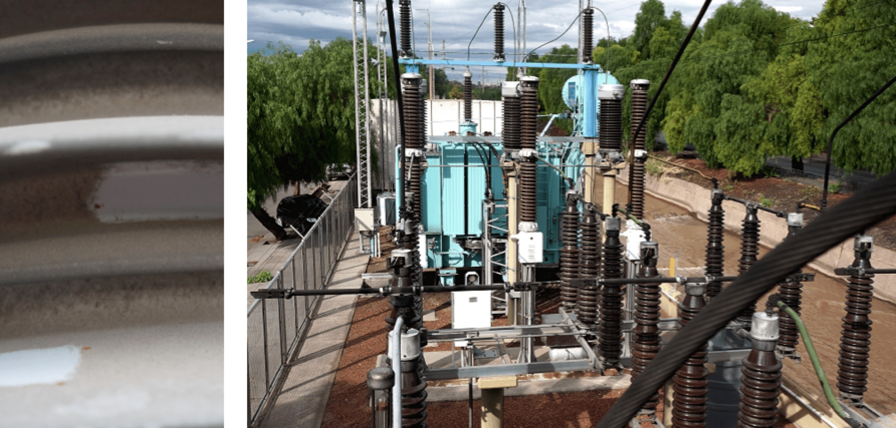
The findings from measurement of ESDD/NSDD are shown in Figures 4 and 5 while Fig. 6 offer examples of insulators contaminated in different manner and Fig. 7 features some of the most contaminated insulators. The place with the highest pollution in this assessment study was a substation in Argentina located in the middle of a busy four-lane highway from each side of the substation (see Fig. 8).
CLICK TO ENLARGE
CLICK TO ENLARGE
CLICK TO ENLARGE
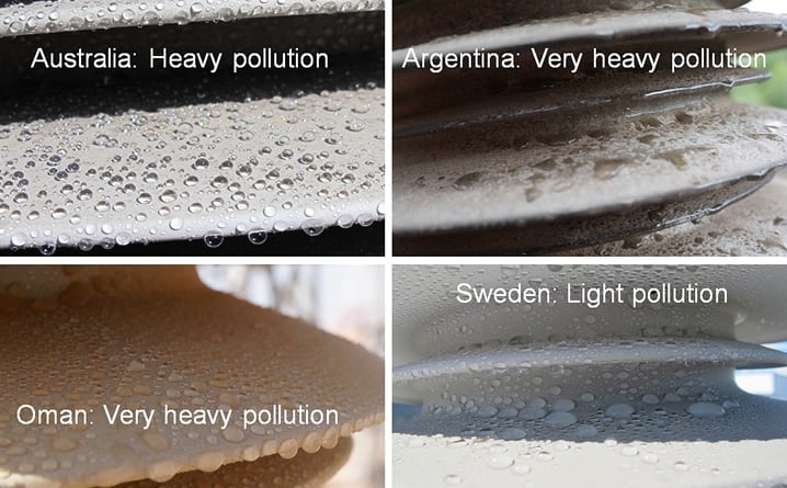
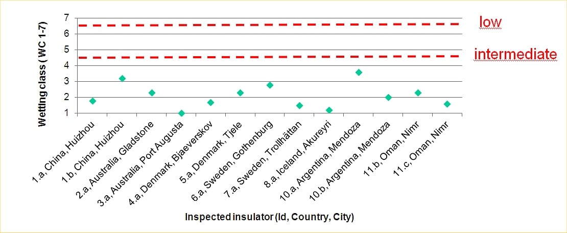
Results of Hydrophobicity Measurements (WC)
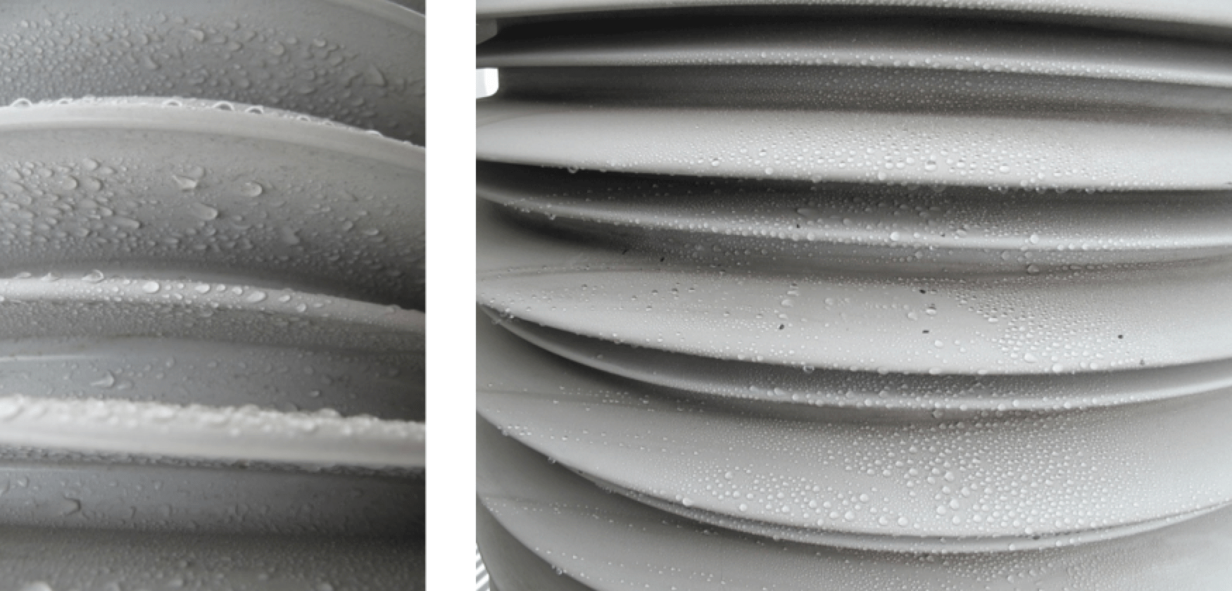
One of the special features of silicone rubber insulators is that, even if surface hydrophobicity is temporarily lost or reduced due to persistent wetting and contamination, it recovers in a relatively short time. In this regard, it is important to note that most of the insulator inspections were performed only a few hours after the substation was de-energized and therefore did not benefit from the influence of such recovery. In this regard, all findings on hydrophobicity can be considered as typical of real service conditions.
CLICK TO ENLARGE
In some industrial environments, the interaction of the pollution layer and silicone rubber can actually lead to ‘super-hydrophobic’ properties and this observation should be investigated further. Still, in general, it can be seen from Fig. 11 that, on average, wettability class (WC) of the insulator sampled was typically between 1 and 3, where Class 1 is completely hydrophobic.
CLICK TO ENLARGE
CLICK TO ENLARGE
Summary & Conclusions
Careful inspection was conducted on a total of 58 hollow apparatus insulators with helically-extruded, HTV silicone rubber housings and operating at 145 kV to 420 kV AC and ±400-500 kV DC. These insulators had been in service from as little as 2 to as long as 17 years, with most at least 5 years in operation. Among this sample, 5 percent were installed horizontally and 95 percent operated in a vertical position. Ten percent were used in DC and 90 percent at AC voltages.
The assessment survey covered all typical environments defined by IEC 60815-1 (desert, coastal, industrial, agricultural and inland) and several of the substations visited reflected a combination of two or more of these environments. The survey also covered 4 of a total of 5 Site Pollution Severity (SPS) classes, as defined in IEC 60815-1 with the only pollution class not represented being ‘very light’. About 50% of the insulators were located in areas with ‘heavy’ to ‘very heavy’ SPS, according to IEC 60815-1.
No significant deterioration was observed on any of the 58 insulators inspected. None had lost their hydrophobic properties – even to an intermediate level – and all had an average WC level better than 4, with the majority between WC 1-3 (where WC 7 is completely hydrophilic and WC 1 is completely hydrophobic). Based on the insulators inspected, all having helical extruded HTV rubber sheds, the following conclusions can be drawn:
• No ageing or deterioration of any significance;
• Good performance with respect to pollution and ageing;
• No signs of ageing of silicone rubber in direct sunshine in areas known to have high levels of UV radiation (i.e. Argentina, Australia & Oman).
It is also noteworthy to point out that it is feasible to make an accurate assessment of the condition of composite insulators using only the simple diagnostic methods/ tools utilized in this survey (i.e. visual inspection, hydrophobicity measurement and pollution sampling).