As the relative importance of electricity continues to grow in the energy transition process, there will be significant movement in present day low and medium voltage networks toward smart grids. With this, the ratio of cables compared to overhead lines at such voltage levels will increase. In fact, some countries have already attained 100 per cent in this shift. At the same time, while overhead lines will remain the dominant means of transmission at high and extra high voltages, the relative importance of cables will increase at these levels as well.
In terms of technology, polymeric cables have become a cost effective and extremely reliable solution for all AC applications and voltage levels and also for most DC cable applications. Given this, the main causes of cable system failures these days are mechanical damage caused by third parties or poor workmanship during installation of accessories. But errors during installation are not solely the responsibility of the workers installing joints. Manufacturers of cable accessories can themselves influence failure rates through better quality materials as well as development of more fault tolerant installation methods.
This edited contribution to INMR by Professor Klaus-Dieter Haim of the University of Applied Sciences Zittau/Görlitz in Germany reviews alternative installation technologies as well as different insulation materials – from the low to the extra high voltages. The focus is on accessory insulation, connection of conductor and cable screen and outer protection.

Insulation Materials & Technologies
In general, the most important requirements for cable accessories are long service life and short installation time. This applies not only to accessory insulation but also to connection of conductor and screen as well as to protection from moisture and mechanical damage. Other important considerations for accessories include cost, universal application and simple, user-friendly installation. Safety is yet another technical requirement. Fortunately, high quality accessory insulation can be designed these days using a range of different materials and installation technologies, depending on voltage level and type of accessory. Moreover, the different types of accessories – whether joints, terminations or separable connectors – should ideally be looked at separately.

Cable Joints
The predominant application of joints is as straight joints, namely the connection of two identical single or three core cable ends. In addition, there are also transition joints, branch joints and stop end joints. The most appropriate insulation material and installation technology in each case varies according to voltage level.
Low Voltage
In the case of low voltage applications, the oldest installation technology for joints sees a combination of a cast iron shell, as outer protection, filled with hot bitumen that offers insulation and moisture protection. This type of bitumen insulation has been used for over a century for straight as well as branch joints for paper insulated as well as polymeric cables from low up to the medium voltages (Fig. 1). The conductor connection in such a joint can be accomplished by soldering, crimping or clamping. One disadvantage is personal risk for the jointer who has to handle hot bitumen.
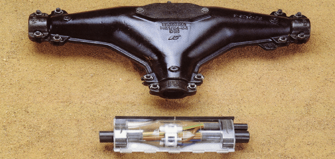
The next generation of joint insulation material has been cast resin and consists of two components either in two boxes or in a special two-chamber bag. Both components have to be mixed after joint preparation and filled into a plastic shell. In this case, the resin functions as insulation and also mechanical and water protection (Fig. 2). The plastic shell only serves a temporary role during the filling process when the resin is still liquid. The long-term behaviour of this material is excellent and it can also be used for live-line work. But one of the two components is often classified as a hazardous material, both for the jointer and for the environment.
Conductor connection in a cast resin joint can be achieved by soldering, crimping or clamping. Cast resin technology is common for all types of branch joints in combination with a special connector system for live-line work (Fig. 3).
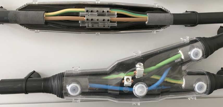
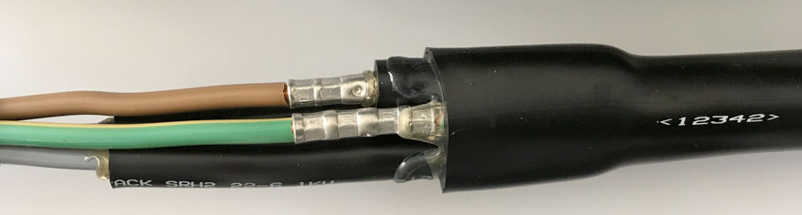
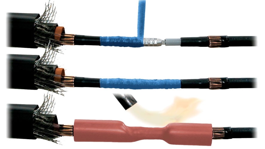
Application of heat shrink tubes is a robust, cost-efficient and highly reliable technology for low voltage straight joints while also offering good long-term behaviour. Fig. 4 shows an installation of insulating tubes with hot-melt adhesive over each connector and a single outer protective tube over all connector insulation tubes as well as over the outer cable sheath. A hot-melt adhesive serves as protection against water. The standard application for conductor connection in this case involves using crimping connectors or shear bolt connectors.
When the heat shrink technology is not deemed applicable, due for example to fire protection requirements, the same joint can be installed using cold shrink tubes. This technology is somewhat more expensive but no heating is necessary. The cold shrink tube material, and especially for the outer protective tube, must be EPDM or a blend of EPDM. Silicone is not appropriate for this application since it is not watertight. Conductor connection is done the same as for heat shrink joints.
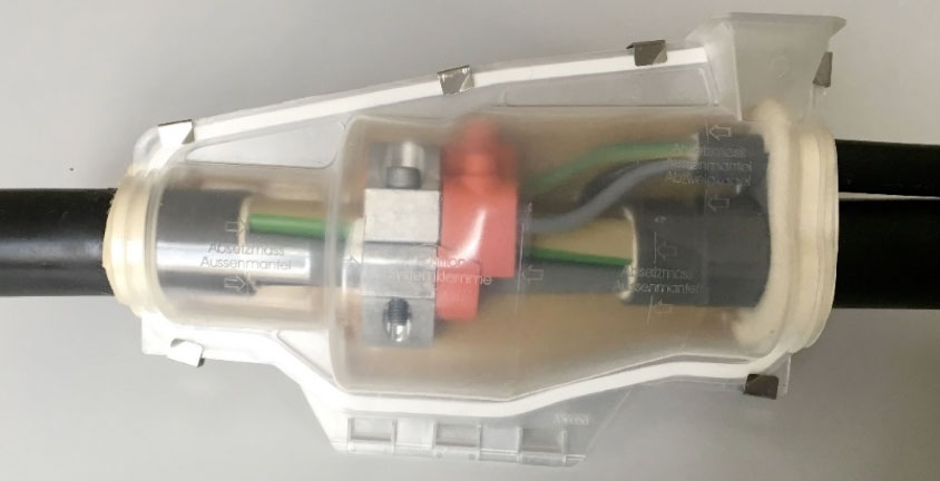
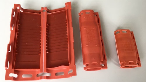
A relatively new technology for low voltage joints is gel technology, whereby a bloc of screw connectors (similar to that shown in Fig. 2) is enclosed by a plastic shell filled with gel (Fig. 5). The function of the shell is mechanical protection while the gel serves as insulation and also water protection.
Medium Voltage
The straight joint is dominant for all types of polymeric cables and therefore the main focus here. The so-called ‘transition’ joint that connects different types of paper and polymeric cables involves a combination of different installation technologies and the broad number of possible variants makes it difficult to review within the scope of this discussion.
As at low voltage, bitumen is the oldest installation technology for medium voltage joints and used initially for paper-insulated cables and later for polymeric cables. However, its use is generally limited up to 15 kV (max. 20 kV). Cast resin is also applicable for medium voltage joints but limited in insulation function only up to 6 kV. As outer protection for a joint, this technology can be used for all voltage levels.
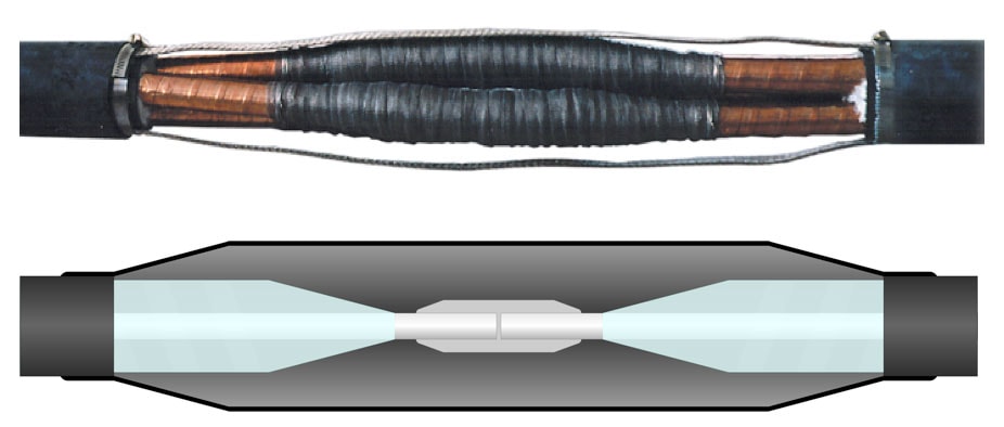
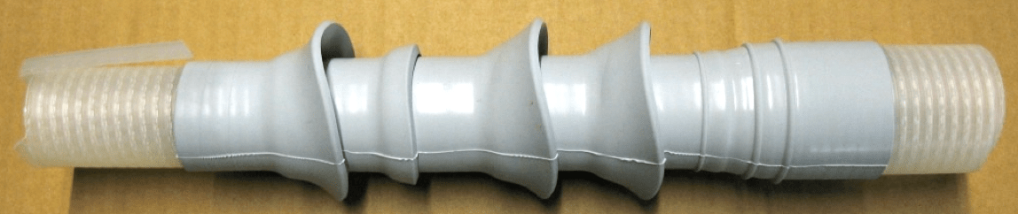
Wrapped technology represented the first new installation technology for polymeric cables. Here, cable insulation can be built up by wrapping two types of self-vulcanizing or self-amalgamating tapes. The first layer is made with conducting tape, wrapped from the inner conducting layer of one cable end over the connector and to the inner conducting layer of the other cable end. The second layer is made of insulating tape, wrapped as a thick layer over the conducting tape and the pencil-shaped cable insulation (see Fig. 6). Thickness of this insulating layer must be much greater than that of the cable insulation to reduce electrical field in micro-gaps and to avoid partial discharges in these gaps. The insulating tape is then covered by a third layer of conducting tape, wrapped from the outer conducting layer of one cable end over the insulating tape to the outer conducting layer of the other cable end. While the wrap joint design is a flexible solution for all polymeric cable types and for all voltages, installation is time-consuming and requires highly qualified workers.
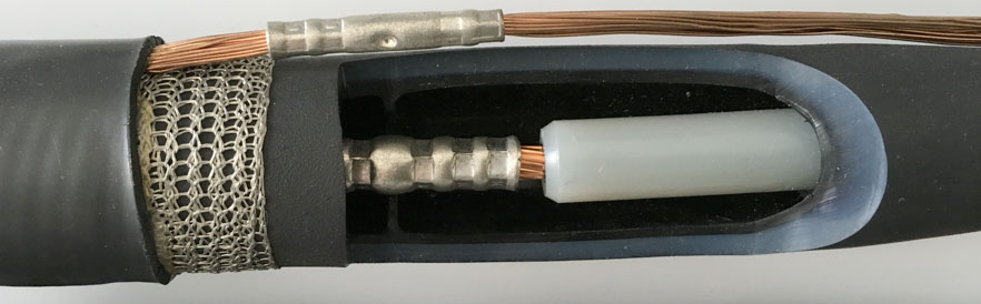
The most widespread installation technology today for medium voltage polymeric cables is heat shrink technology. This method uses heat shrinkable polyolefin tubes for joint insulation. Before shrinking, these tubes are available in a wide range of application diameters and installation time is therefore much shorter than for wrap-joints. One major difference for medium and high voltage accessories compared to low voltage applications is the need for electric field control. In this regard, the key trend in stress-control sees combining different materials and technologies, such as silicone rubber elements (Fig. 7). Application of a void-filling, stress-controlling tape (blue or yellow) is essential to avoid partial discharges. The major disadvantage of heat shrink joints is construction of the joint insulation, which takes place entirely in the field and requires a flame or hot air gun. There is also no possibility for pre-testing in the factory.
Slip-on and cold shrink technologies overcome these disadvantages since pre-testing in the factory is possible for both and no heating is required. In the case of slip-on technology, a one-piece joint body needs a parking position on the cable insulation or on the outer sheath of the cable. Relatively long outer protection is necessary for parking on the cable insulation while a highly flexible insulation body is required for parking on the outer sheath (Fig. 8).
A three-piece insulation body is yet another design option, often used for medium voltage joints and in some cases for high voltage joints as well. Production and installation is easier than for a one-piece joint and there is no need for a parking position on the cable insulation. However, there are additional interfaces in the joint and this increases risk of errors. In general, the ideal material for a three-piece joint is silicone due to its excellent interface behaviour. Suitable materials for one-piece medium voltage slip-on and cold shrink joints can be silicone or EPDM, each with about equal preference.
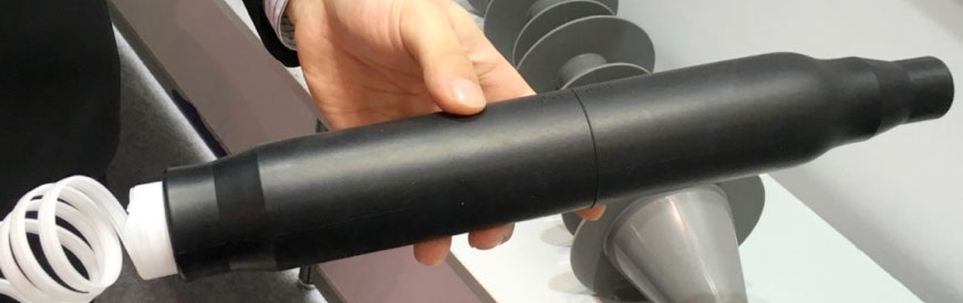
The latest design solution for medium voltage joints is cold shrink technology. Fig. 9 shows removal of a spiral from within a pre-expanded one-piece insulation body. This technology combines the advantage of a single-piece, pre-tested joint body with an easy installation procedure.
High Voltage
There are basically three installation technologies that are appropriate for high voltage polymeric cables: wrap, slip-on and cold shrink. As mentioned above for medium voltages, wrap technology is highly time-consuming and more susceptible to possible worker errors. It is therefore the least ideal for high voltages. Rather, slip-on technology is currently the most common installation method for high voltage joints. Fig. 10 shows a sectional view of a slip-on joint. The cable screen is prepared for cross bonding and the joint’s outer protection involves a cast resin solution.
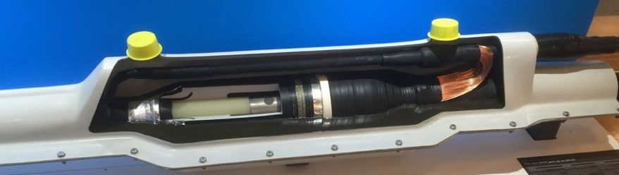
and with cast resin outer protection.
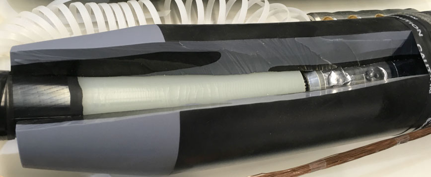
Cold shrink technology is cutting-edge design not only for medium voltage joints but for high voltages as well. Fig. 11 shows a sectional view of such an installed cold shrink joint. This is a one-piece silicone insulation body, pre-expanded on a spiral. The main advantage is ease of installation, with silicone being the dominant insulation material for high voltage AC joints.
Terminations
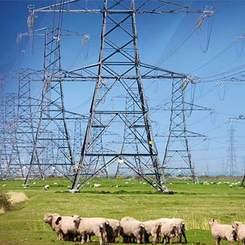
Terminations, especially outdoor terminations, serve the important function of connecting cables to overhead lines, switchgear and transformers. In this role they are exposed to a variety of service stresses, from electrical to mechanical to weather to occasional interaction with wildlife. Over the years, different installation technologies and insulation materials have become widely accepted in the cable termination industry. Application of these different technologies and choice of optimal insulation material depend mainly on voltage level as well as on specific type of termination. There is no need to look at low voltages for this application since no stress control is necessary and the cable can therefore be connected directly to switchgear, without a termination.
Medium Voltage
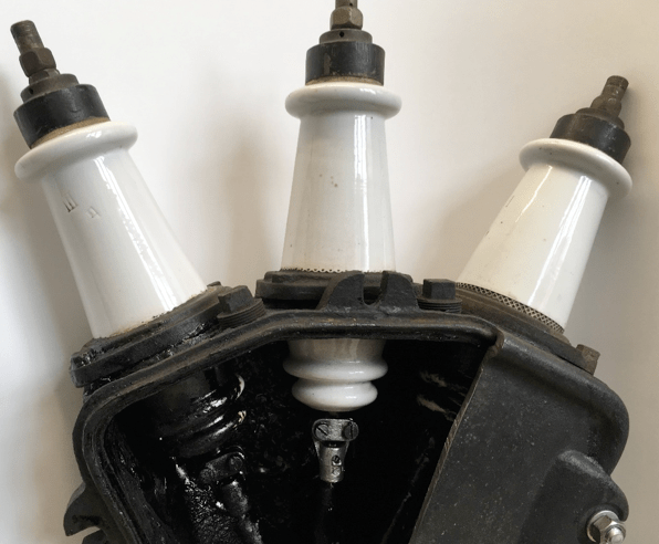
The oldest installation technology for medium voltage paper-insulated cables was the combination of a cast iron termination body with porcelain bushings and filled with hot bitumen for insulation and moisture protection within the termination body (see Fig. 12). This type of termination, however, is not generally used for polymeric cables.
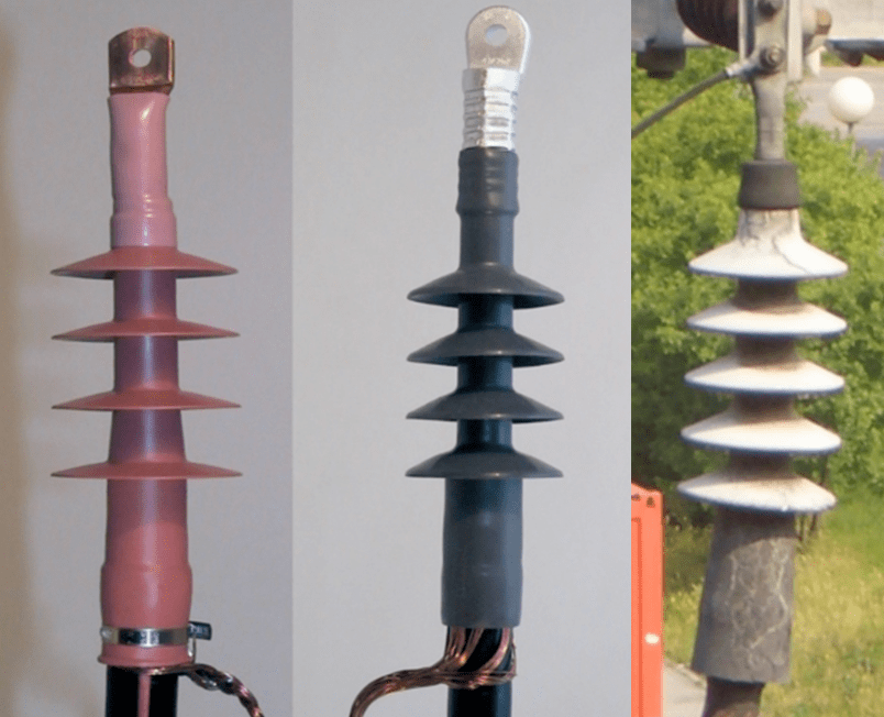
Heat shrink technology is the most applied installation technology for medium voltage terminations. This method uses heat shrinkable polyolefin tubes for insulation and heat shrinkable stress control tubes and sheds. A hybrid technology combines a slip-on silicone stress control element with heat shrink insulation tube and with slip-on silicone sheds (Fig. 13). All sorts of heat shrink terminations offer attractive cost for a robust product with long service life. The only problem can be use of a flame during installation.
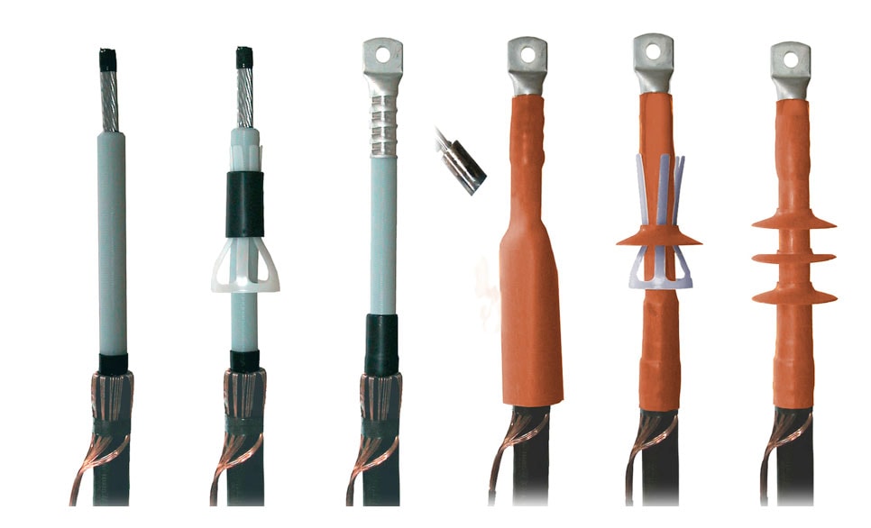
In recent years, more and more slip-on termination and cold shrink solutions have found the way into the market (Figs. 14 & 15). The advantage of a slip-on termination is unlimited storage time, easy and quick installation and good hydrophobicity of the silicone typically used in this type of termination. In the case of medium voltage terminations, a wide range of cross-sections is important for only a single size of termination. Most slip-on terminations are single-piece solutions although a smaller proportion sees combination of several elements and made on EPDM (Fig. 14 right). A conducting carbon path is visible on the termination shown in this example, which is in fact one of the main disadvantages when using EPDM for terminations. The advantage of cold shrink technology when it comes to ease of installation is less important for a termination compared to a joint since there is no parking position on the cable sheath. A cold shrink termination can be pre-expanded on a spiral or on a tube (Fig. 15).
High Voltage
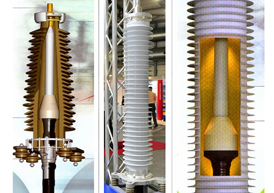
The classic outdoor termination for high voltage AC XLPE cables is the fluid-filled termination with porcelain insulator (Fig. 16a). This type of termination has long field experience and offers excellent resistance against tracking, radiation and bird-pecking. Nonetheless, over recent years composite insulators have been growing in market acceptance due to additional advantages they offer, including excellent hydrophobicity, low weight and superior seismic and explosion performance (Fig. 16b).
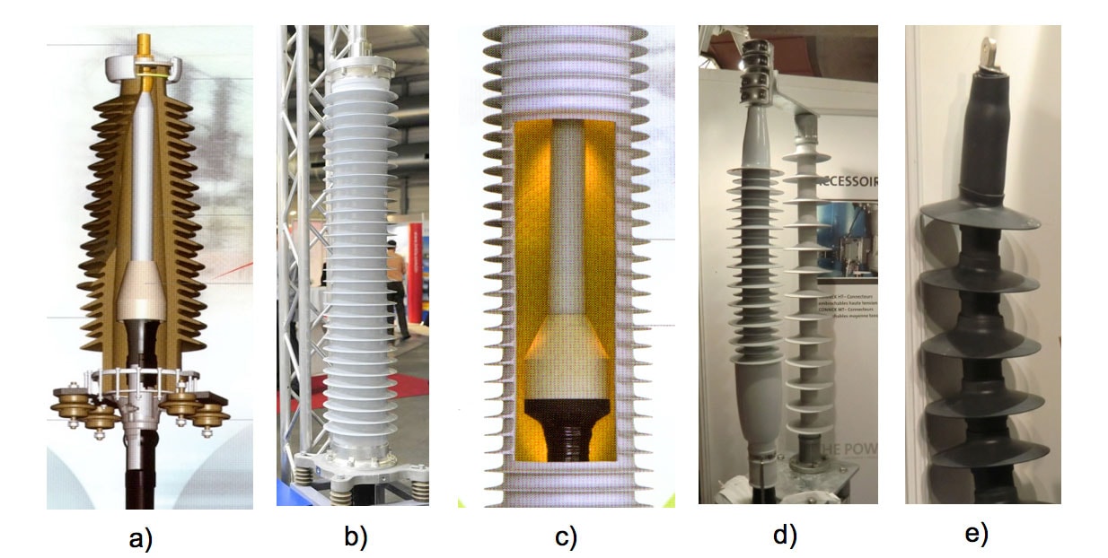
a) Fluid filled HV termination with porcelain insulator.
b) Fluid filled HV termination with composite insulator.
c) Stress control element, Insulator filled with gel or gas.
d) Slip-on dry type HV termination.
e) Cold-shrink dry type HV termination.
Figs. 16d and 16e show the newest generation of terminations, developed initially for the medium voltage level. The main advantages of these so-called dry type terminations are ease of installation, no need to fill with oil and no risk of explosion.

Separable Connectors
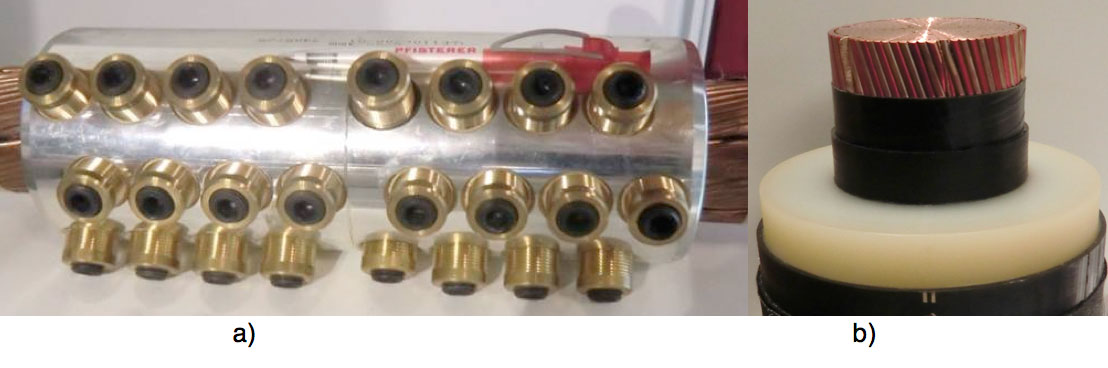
Medium and high voltage cables are increasingly being connected to SF6 or solid-insulated switchgear and to oil and solid-insulated transformers and plug-in connectors are often used for these applications. There are two standardized plug-in connector systems: the outer cone connector system which is widely used in medium voltage ring main units and where the cone is outside the bushing (Fig. 17b); and the inner cone system often used at medium voltage primary substations and in all high voltage applications, where the cone is inside the bushing (Fig. 17a).
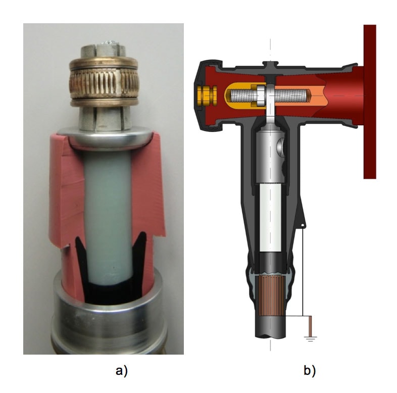
a) Medium voltage inner cone system;
b) Medium voltage outer cone system.
Medium Voltage
Fig. 17b shows the outer cone system on a bushing, including the contact system. One of the advantages of this system is the possibility to attach two or three connectors to one bushing or to a combination of connector and surge arrester. The insulating material in this case can be silicone, usually in combination with some metallic enclosure, or EPDM without metallic cover. The reason for using EPDM as well as the outer cone system are based not only on cost of material but also on the requirement that a separable connector should be fully screened and touchable, providing complete safety for personnel. This can be achieved in an easier, more reliable and more cost-effective way using an outer semi-conducting layer made of EPDM versus one made of silicone. Maximum application voltage for the outer cone system is 72.5 kV. Fig. 18 shows three different connectors at this voltage level, two made of silicone and one of EPDM, installed on switchgear in a wind turbine.
The inner cone system is used most often at important primary substations and, in this case, the insulating material is only silicone. This kind of dry-type, plug-in connector can also be used for outdoor terminations as well as joints and is expected to become one of the main elements of future cable accessories at all voltage levels
High Voltage
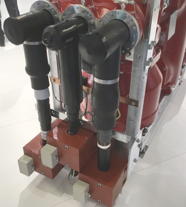
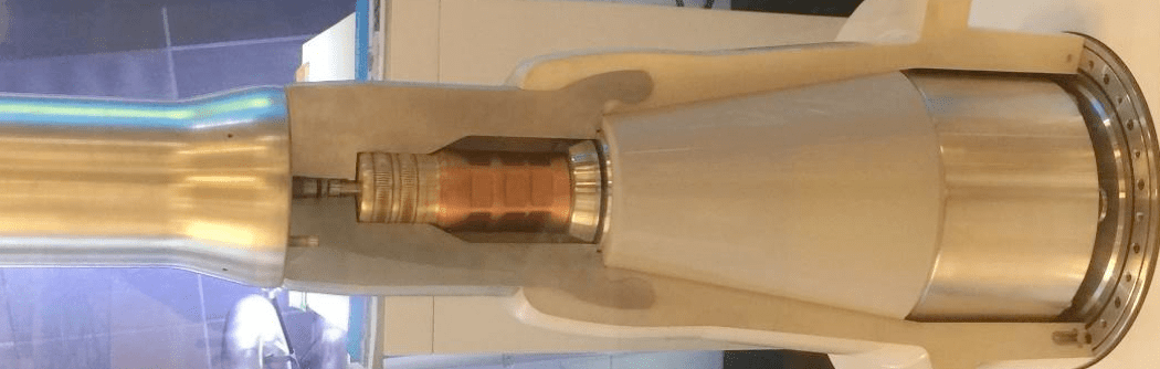
The inner cone system is the only type used for high voltage applications. With this system, much higher interface pressure can be achieved making it suitable for voltages up to 500 kV (Fig. 19).
Technologies for Conductor Connection
The connector is one of the most important components in a cable joint and can be the reason behind thermal destruction of its insulation. The connector must be able to carry the cable’s nominal current as well as the maximum short-circuit current of the network for a certain time, without overheating. Connecting cable conductors can be accomplished by soldering or welding, by compression or by using a shear-bolt connector. Since the heat generated during soldering or welding can be a problem for XLPE cables, use of compression or mechanical connectors has become most widely accepted.
Low & Medium Voltage
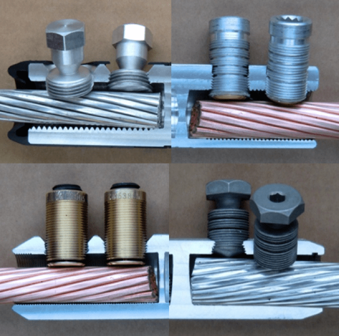
The classic compression connector for low and medium voltage straight joints (Figs. 4 & 8) is increasingly being substituted by the shear bolt connector (Fig. 19). This type of connector is suitable for the many conductor sizes, shapes and materials available on the market and offers much less chance of the jointer committing installation errors. This gives the bolt type connector an obvious advantage over the compression connector. A compact clamp is often used for low voltage branch joints, especially for live-line work.
High Voltage
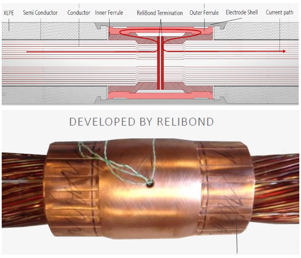
More and more, shear bolt connectors are becoming available even for high and extra high voltage cables with cross-sections up to 3500 mm², (Fig. 22a) and connector technology is moving in this direction. In the case of AC cables with large cross-sections, the so-called ‘skin effect’ has great influence on a cable’s transmission capability. To reduce increased conductor resistance, application of a Milliken conductor is possible whereby the conductor strands are individually insulated. Another way to counteract this phenomenon is by using enameled wire conductors (Fig. 23b). In this case, a special connector or special conditioning of the conductor becomes necessary.
b) AC cable with enameled wire conductor.
Cable Screen Connections
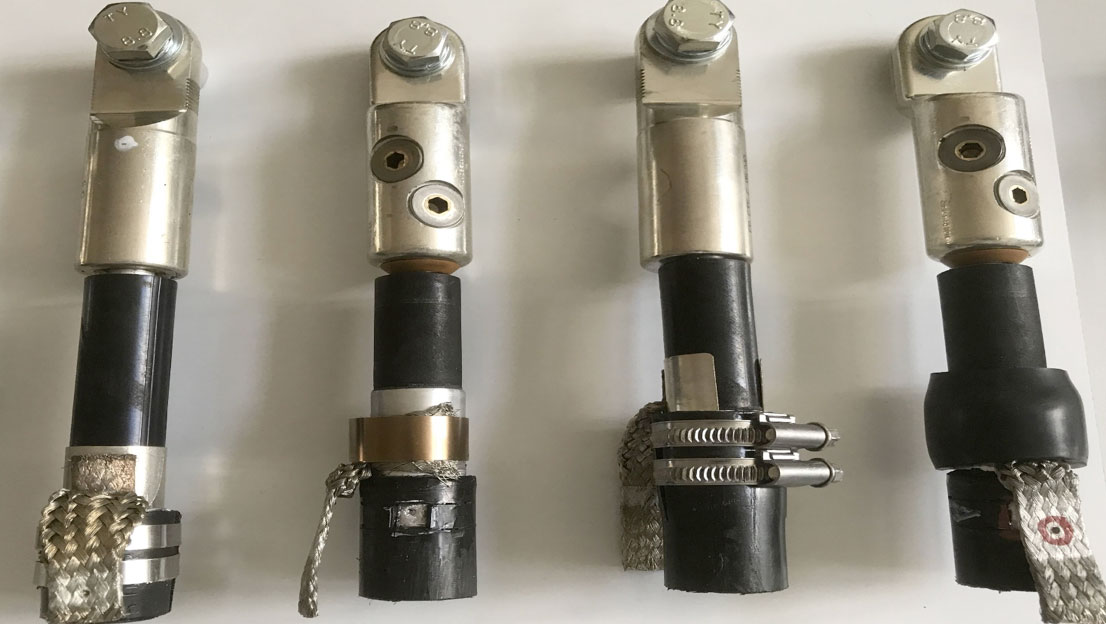
Design of the cable screen can differ substantially and this has substantial impact on reliability of cable accessories. Selection of screen depends on laying as well as economic factors. Cables available on the market employ copper wire screen, copper tape screen, a welded aluminum sheath or a corrugated sheath of aluminum or copper. Other manufacturers prefer cables with thick lead sheaths or with some combination of copper wire screen and laminated aluminum screen.
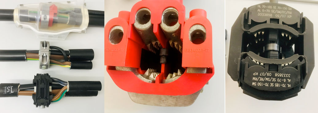
This same variation exists in terms of connection of these metallic screens in joints or when connecting the screen to the earthing device at cable ends (i.e. terminations). In the case of a copper wire screen, the connection in joints and termination is relatively straightforward and presents little risk of serious problems. In other cases, it is essential to implement extremely good contact between the metallic screen and one or more of the copper braids. Fig. 23 offers an example of the most complex connection for cables with laminated aluminum screen. This can be accomplished by means of constant force springs or, alternatively, by using hose clamps or heat shrinkable or cold shrinkable tubes.
The common problem for all kinds of screen connection devices relates to capability of transmitting service and fault currents from the screen to ground potential. Deterioration of the contact can also affect reliability of the accessories. Finally, it is important not only to have good contact but also to ensure adequate heat emission from the screen to the outer sheath of the cable to guarantee good long-term behavior. For cables having high service current and thus also high screen current, application of cross bonding can reduce screen current. Unlike conductor connectors, there is still no test standard for all the different kinds of screen connections. That is why CIRED established an international Working Group in 2017 to propose a test recommendation. Their final report is expected to be available in 2020.

Outer Protection
One of the main factors in possible degradation of accessory insulation is water. Outer protection, especially for joints, is therefore extremely important in ensuring long-term performance of cable accessories since moisture permeation can influence the inner insulation material and lead to failure.
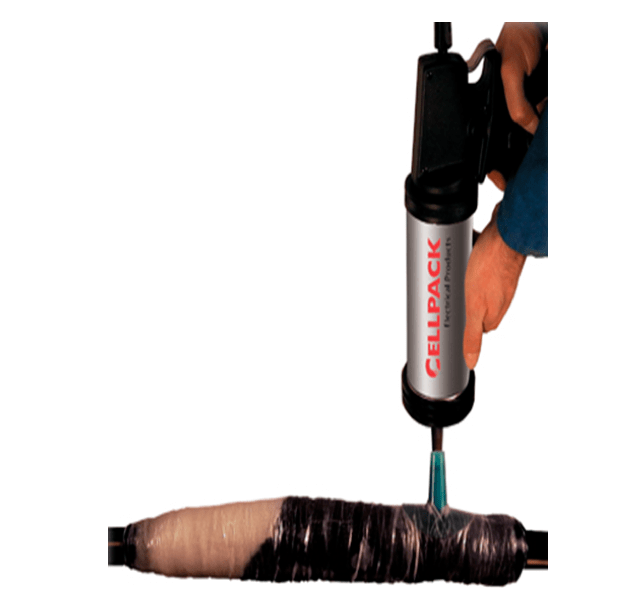
The oldest solution for good mechanical as well as water protection is the cast iron shell filled with bitumen shown in Fig. 1. An improvement in terms of work safety and also offering excellent water tightness has been the cast resin system shown in Figs. 2 and 3 for low voltage and in Fig. 10 for high voltage. Injection of resin in a system of different tapes is also a flexible and reliable solution for mechanical and water protection for all types of joints (Fig 24). In the case of low and medium voltage straight joints, a thick wall heat shrink tube with hot melt adhesive is another cost-effective and reliable solution (Fig. 4). For straight joints, replacement of the heat shrink tube by a cold shrink EPDM tube in combination with a sealing mastic is another possible solution while, for low voltage joints, gel technology also offers the necessary mechanical and water protection (Fig. 5). The function of the shell is mechanical protection whereas the gel offers the insulation and water protection.
Developments to Watch
Medium & High Voltage
High Temperature Superconductor Cable
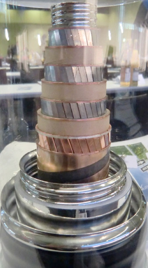
In recent years, application of high temperature superconductors (HTS) for medium and high voltage power cables has moved from the prototype phase to field application. Fig. 25 shows design of the 10 kV three core coaxial cable with nominal current of 2.31 kA and total power capacity of 40 MVA, as installed in the city of Essen in Germany. The complete system in this case consists of the one kilometre coaxial cable surrounded by the cryostat, one cable joint, two terminations, a current limiter and the refrigeration system. Given availability of different single core and three core HTS cables for different voltages, and also suitable terminations as well as joints, all the technical requirements for broader commercial application appear to be fulfilled.
High Voltage
New Generation of Dry Type, High Voltage Terminations
An outdoor termination for high voltage XLPE cables is generally composed of a hollow insulator (porcelain or composite), an electrical field control element and filled oil or gas as the insulation material. The environmental problems linked to oil and risk of explosion of porcelain housings have led to development of slip-on and cold shrink technologies. For example, one innovation is replacement of oil by a special silicone gel and the first presentation of a gel-filled high voltage termination for 138 kV and 230 kV was at the 2013 INMR WORLD CONGRESS by A. Watanabe. This paper showed that comparison of measured values of silicone oil and silicone gel revealed that the gel has superior insulation performance, with higher volume resistivity as well as extremely low power factor. Among the other interesting features of the gel: no special tool is needed for injection into the termination; air bubbles come out without using a special device; the gel is flexible and adheres well to different materials.
Indeed, two market ready, gel-filled high voltage terminations were recently presented at Jicable. Fig. 26 shows one solution where the gel is filled into the hollow composite insulator in the factory and assembly of the termination is similar to installation of a slip-on termination. The other solution is to fill the silicone gel after installing the termination into the hollow insulator.
High Voltage
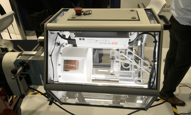
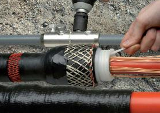
Connection of AC Cables with Enameled Wire
Use of enameled wire conductors is the most efficient solution to reduce increased conductor resistance influenced by the skin effect for AC cables having large cross-sections (Fig. 23b). In this case, a special new connector, in combination with conductor preparation, offers new possibilities for the joints (Fig. 27). An electro-welding device can realize the front contact for each wire of the enameled conductor (Fig. 28).