Three types of arresters are used to protect high voltage power cables. The first are known as ‘deadfront’ (IEEE) or ‘separable’ (IEC) arresters and used primarily on distribution systems such as in pad-mounted cabinet applications. A second less common type is used for cable protection and is called a sheath voltage limiter. This is an air-insulated arrester primarily used on high voltage cables and found either in a submerged link box or on the riser pole near the cable terminator. A third type, the riser pole arrester, is universally applied to protect cable systems. This is used on both distribution and transmission systems and always located on a riser pole or at the overhead to underground transition point at a substation.
This edited past contribution to INMR by Jonathan Woodworth reviewed the fundamentals of these devices as well as why they are important in protecting cable systems.

Deadfront & Separable Arresters
Deadfront (Fig. 1a) and separable arresters (Fig. 1b) are relatively recent types of arresters introduced to the field of surge protection. It was not until introduction of the MOV arrester that this type of arrester was even possible. In 1979, a U.S. patent was issued and appears the earliest description of this device.
Definitions
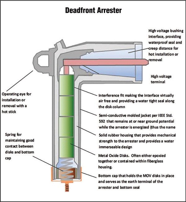
Deadfront Arrester
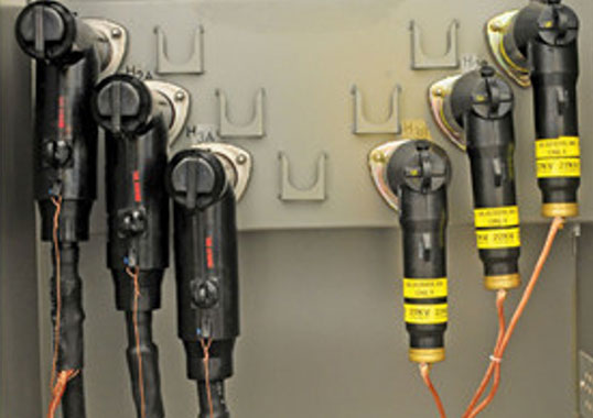
This arrester is assembled in a shielded housing that provides system insulation as well as a conductive ground shield and is intended for installation in an enclosure to protect underground and pad-mounted distribution equipment and circuits. Typically, 200A load break versions can be connected or disconnected with the system energized. However 200A dead-break IEEE designs also exist. There are several names for this type of arrester including elbow arrester, parking stand arrester and bushing arrester (in the IEEE market).
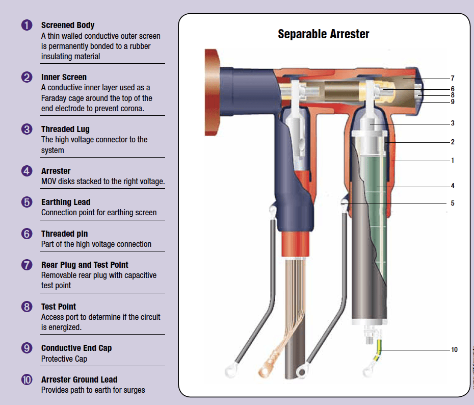
Separable Arrester
A separable arrester, assembled in an insulated or screened housing and providing system insulation, is intended for installation in an enclosure to protect distribution equipment and systems. Electrical connection can be either by means of a sliding contact or using bolted devices. However, all separable arresters are dead-break arresters (IEC). In the IEC market, separable arrester is the only term used to describe this type of arrester. In all cases, these arresters are used to protect cable systems in the medium voltage range, i.e. 11- 42 kV.

Sheath Voltage Limiter
A sheath voltage limiter is an arrester used to clamp the voltage induced on the sheath of an underground medium or high voltage cable during a fault on the system.
Riser Pole Arrester
This is an air-insulated arrester used to protect high voltage underground cable insulation and equipment. Riser pole arresters are generally mounted on the transition tower or pole. A riser pole arrester can be distribution type or station type and not classified in any standard.
Voltage Doubling Effect
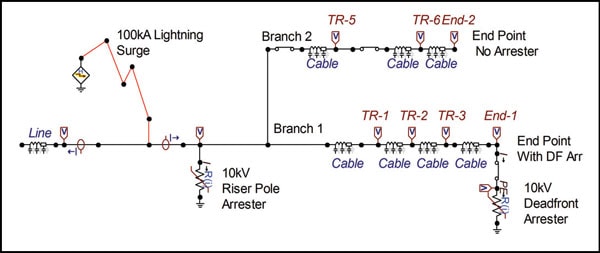
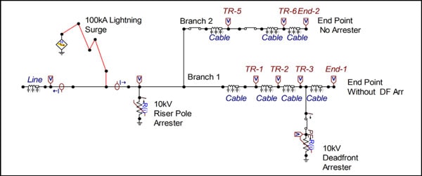
Separable and deadfront arresters are special arresters used primarily to mitigate the threat of voltage doubling effect at open points on underground circuits. When a lightning surge hits a riser pole arrester, the arrester clamps it but allows an ongoing surge with the magnitude of this clamping voltage to continue on into the underground circuit. Fig. 3 shows a circuit that has two underground branches in a distribution underground network. Branch 1 has a deadfront arrester at its end point while Branch 2 does not.
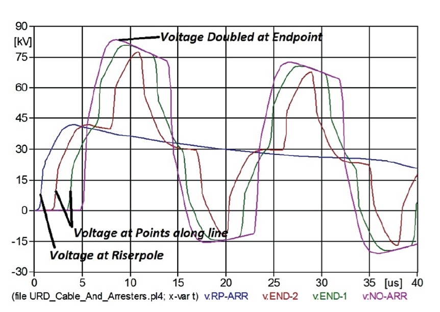
Once the ongoing surge from the riser pole arrester meets an endpoint in the underground circuit, it will double in magnitude in that circuit (as shown in Fig. 4).
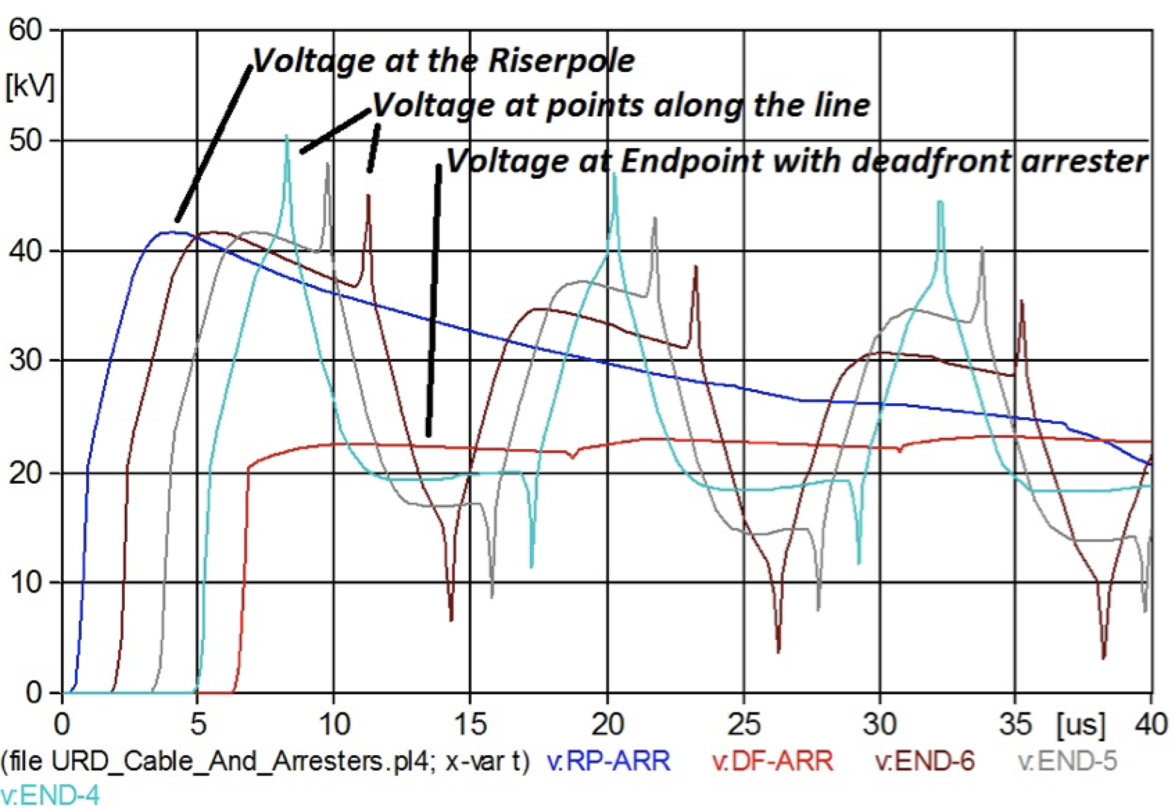
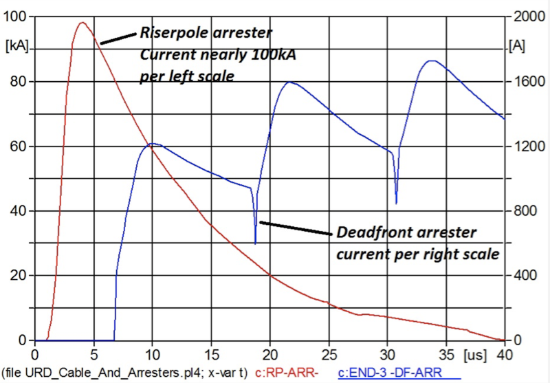
By contrast, when the same surge meets the endpoint in Branch 1, where a deadfront arrester is installed, voltage decreases as shown in Fig. 5. Even though the riser pole arrester and deadfront arrester are of the same rating, the clamping voltage at the deadfront is much lower than at the riser pole. This difference is due to the fact that, while the riser pole arrester conducts nearly the full lightning stroke current (see Fig, 6), the deadfront arrester conducts only a few kA.
Deadfront Arrester Installed Back from End Point
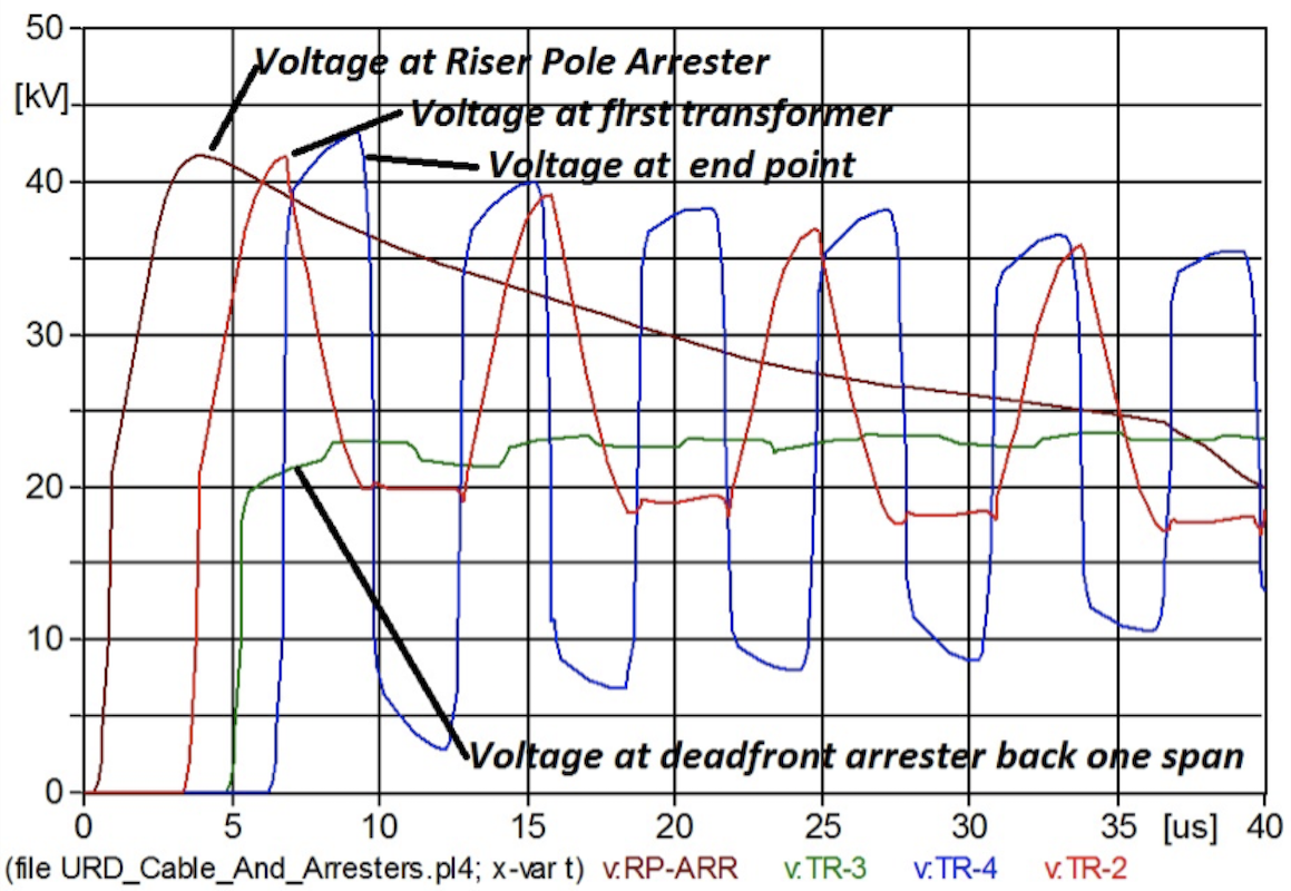
In the case where a deadfront arrester is placed one transformer back and not at the endpoint of the branch (as in Fig. 7), results can be interesting. The end point voltage of the branch without the arrester still doubles but now only doubling the level of the deadfront arrester, as illustrated in Fig. 8. It does not double to the level of the riser pole arrester (as in Fig. 4).
Dead Front/Separable Arrester Rating Considerations
Both the deadfront and the separable arrester are typically rated at 5 kA. The IEEE deadfront arrester can also be rated as light duty, which is one energy handling class below a normal duty arrester (5 kA). These lower energy ratings are appropriate since underground circuits are universally protected by an arrester at the riser pole. As shown in Fig. 6, the riser pole arrester conducts the vast majority of the surge current, leaving only a few kA of current for the deadfront arrester to deal with. A unique characteristic of separable and deadfront arresters is the configuration of the high voltage terminal. Since the high voltage end must mate with a bushing, designs are specific to the bushings available in both IEEE and IEC markets. In the IEEE market, there are three common interfaces: 15, 25 and 35 kV. In the IEC market, several interfaces also exist. They include, among others: 250A, 400A, and 630A. All are deadbreak.
This type of arrester is also configured in several formats depending on how it is to be installed in the circuit. For example, the parking stand style is intended for mounting on a bracket (known as a parking stand of a pad-mounted transformer). An incoming line can then easily be terminated directly into the arrester, thereby avoiding an open endpoint. Other variations include the inline arrester, where the incoming line feeds through the arrester and then into the transformer. In all cases, such arresters perform identically.

Deadfront Arrester Failure Mode Considerations
The failure mode of such an arrester is tested in a different way than for other arrester types. That is because, for such arresters, it is permitted that disks be ejected from the bottom during a failure event – but not from the side. This is acceptable only because the arrester is generally installed in an enclosed space where ejection of parts would not pose a threat to safety as in the case of an overhead arrester. Moreover, the fault currents used for testing are also much lower since it is not common for such currents to be excessively high in any underground distribution circuit.
Deadfront & Separable Arrester Installation Considerations
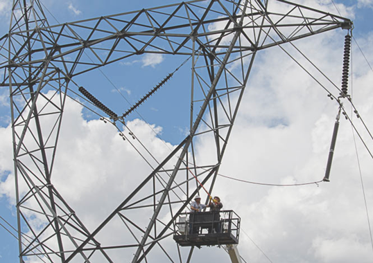
As with all arresters, it is important for the ground lead to be as short as possible. The lead should also be attached in a way that does not stress the arrester.
Sheath Voltage Limiter (SVL)
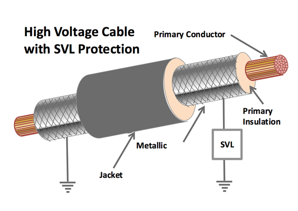
As shown in Fig. 10, a sheath voltage limiter is often mounted on an overhead to underground transition pole. While the riser pole arrester is applied as any line arrester on a high voltage circuit, i.e. to protect the conductor insulation, the sheath voltage limiter is applied for a different purpose. Its role is rather to clamp the voltage induced onto the metallic sheath during a fault on the system. Fig. 9 is a simple diagram defining common cable components where an SVL is located.
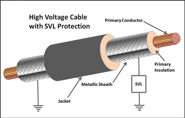
Metallic sheaths are used for durability and to better manage the electric field within a power cable. But these come with an issue. Since the sheath is close to the primary conductor, it can develop currents that can lead to significant losses if it is grounded at both ends. To reduce losses, one end of the sheath is grounded and the other is left open. While this eliminates the losses due to normal operation, this practice also results in a transient issue. Should there be a fault on the system and high currents are conducted through the cable with sheath open at one end, high voltage can be induced onto the metallic sheath.
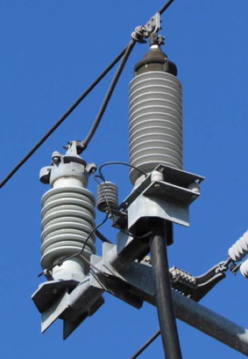
To resolve such a transient voltage event, an SVL is connected to the floating end of the sheath. The arrester is then grounded such that, during a fault, it clamps the voltage developed on the metallic sheath to levels that will not cause puncture to either the primary insulation or the jacket. A standard arrester can be used as a sheath voltage limiter. Voltage ratings are usually below 15 kV and energy handling ratings can vary from distribution arrester levels to Class 2 or 3 levels. Fig. 10 shows an SVL mounted next to a 69 kV termination. For longer lines, an SVL is installed every 300 to 600 meters. In this case, the arrester is mounted either in a link box in an underground vault or in a pad-mounted cabinet.

Riser Pole Arrester
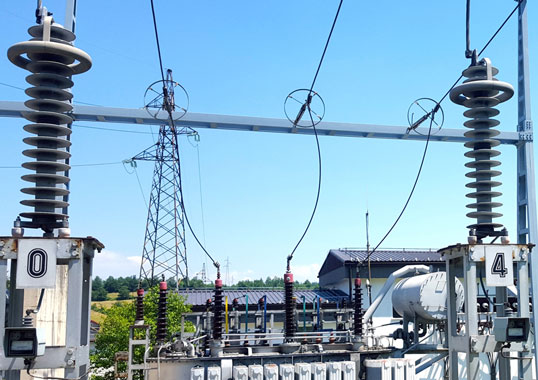
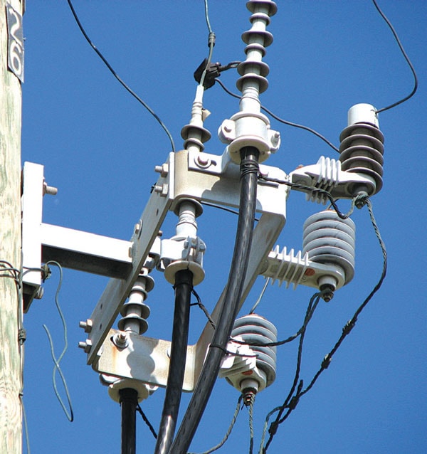
Because the riser pole arrester is the first line of defense for cable and underground equipment, it is very common, even where there is relatively low lightning activity. It is typically mounted on the riser pole at the transition point between the overhead and underground circuit and takes its name from this installation. Its function is discussed above in the analysis of voltage doubling in an underground circuit. Fig. 11 shows a distribution riser pole arrester arrangement while Fig. 12 shows a typical high voltage configuration.
Conclusions
At present, these arresters represent but a fraction of all surge protection applications. Still, in spite of their small numbers, they perform a significant asset protection role since without them underground power transmission would be impossible. Moreover, given that underground circuits are increasing their share of all power transmission, these arresters are more and more important for surge protection.