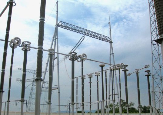
Station post insulators are indispensable for apparatus installed at HV substations. Porcelain and glass designs are the classical technologies applied for more than a century and these are already well established and standardized in testing as well as in selection process. However, application of composite station post insulators is now growing steadily.
This edited past contribution to INMR by Dr. Jens Seifert of Reinhausen Power Composites, who also serves as Chairman of IEC TC 36 Insulators, reviews the state-of-the-art of all technologies as well as related standards and also predicts which applications will favor selection of composite station posts in the future.


Alternative Types of Station Posts
Porcelain Station Posts
Porcelain station post insulators cover a voltage range up to 765 (800) kV, with maximum cantilever strength classes in the range 20 to 30 kN. Single units can be manufactured to a length of 3000 mm. For voltage levels exceeding 245 kV, assemblies (or multi-unit stacks) are used consisting of 2 or more individual units connected by metal flanges. Standard IEC 60273 is applicable for selection of IEC types according to characteristic values and the related test standard is IEC 60168. Post insulators according to ANSI standard C29.9 are defined as a ‘catalogue’ (TR types) according to characteristic values and covering types up to 765 kV. ANSI C29.9 also defines applicable tests. Porcelain station posts in accordance with IEC 60273 and ANSI C29.9 are today well specified and can be ordered according to C- or TR-Codes respectively. However both standards are relatively old and need revision in order to accommodate the latest technologies as well as updated definitions of pollution classes as per IEC 60815-2. Modern production technologies offer high-strength designs optimized in shape, weight and shed profile. For applications under severe pollution, RTV silicone coatings can be used to improve electrical performance.
Glass Station Posts
Glass station posts, also specified in IEC 60273, consist of individual glass discs assembled by means of cement. Complex housing profiles can more easily be realized with this technology. Application of such multi-unit post insulators is rare at most modern substations, although installations still exist from the 1950s and 60s. For applications under severe pollution, RTV silicone coatings can be utilized to improve electrical performance.
Composite Station Posts (CSP): Solid Core Type
CSPs, first introduced during the early 1980s, consist of a solid core fiber reinforced polymeric (FRP) core and an elastomeric housing. Typical FRP core diameters range from 45 to 100 mm with maximum diameters rarely exceeding 130 mm. Application in substations derived from past application of composite line post (CLP) insulators, mainly in the United States. CSPs with solid cores are typically applied up to 245 (420) kV. For higher voltage classes, relatively high mechanical deflection limits their broader application. The test standard for this product is IEC 62231 while mechanical and electrical characteristics are defined in IEC 62231-1, which also includes ANSI types utilized in North America. C29.19 is the relevant standard for such ANSI types.
Composite Station Posts: Hollow Core Type (CHSP)
At voltage classes higher than 245 kV, height and bending moment of stations posts both increase. As a result, much effort is needed to satisfy application requirements using solid core CSP designs (i.e. with core diameters >170 mm). This makes this technology less cost competitive versus porcelain types. At the same time, composite hollow core station posts (CHSP) and hybrid station post (HSP) insulators have begun to enter this application portfolio. For example, CHSPs have already been realized for 800 kV HVDC and 1100 kV UHV applications, with connection length of more than 10 m and tube diameters of 500 to 1000 mm. Bending moments of more than 1000 kNm are feasible with this technology. The hollow volume inside these posts has to be filled with some electrically inert medium e.g. insulating gas foam. The applicable test standard is IEC 62772.

Hybrid Station Posts (HSP)
Hybrid station posts, according to IEC TR 62896, are combinations of porcelain (ceramic) and composite (polymeric) technologies. The core of an HSP is typically solid core porcelain made from high-strength mass (C-130) while the housing is made of an elastomeric material, whether liquid silicone rubber (LSR) or high temperature vulcanized (HTV) silicone. These are applied by means of injection molding or some extrusion process. The advantages of HSPs are low deflection of the rigid porcelain core with high E-modulus under cantilever load. Moreover, the hydrophobic silicone housing improves electrical properties under polluted conditions. Typical applications are large HVDC post installations as well as posts for disconnector switches (i.e. where low deflection is required).
Technologies
In the case of porcelain station post insulators, the main technologies to produce cylindrical pugs are:
• Extrusion
• Hydrostatic compression
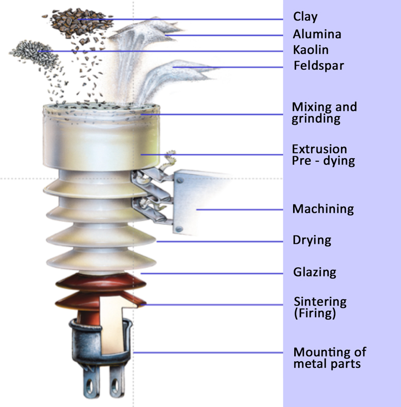
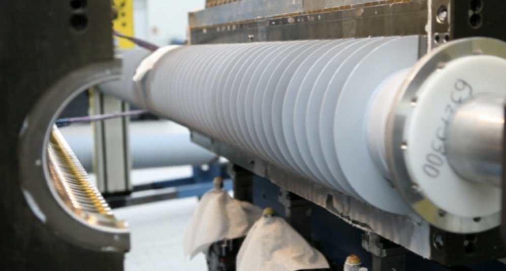
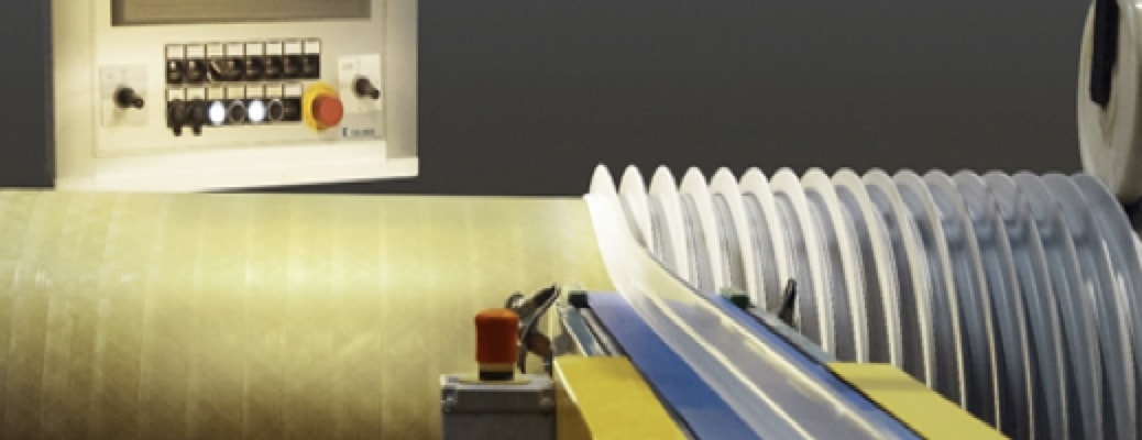
After production of the pugs, shed shapes are formed in a turning process with subsequent sintering at 1200-1300°C and assembly (cementing) with metal end fittings (i.e. caps or flanges). Fig. 1 summarizes these principal production steps.
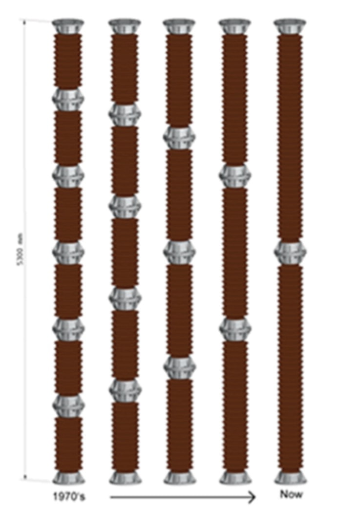
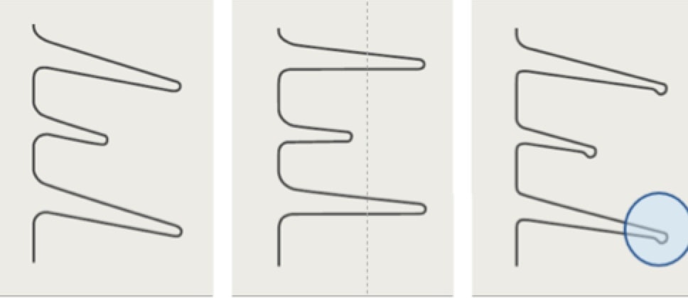
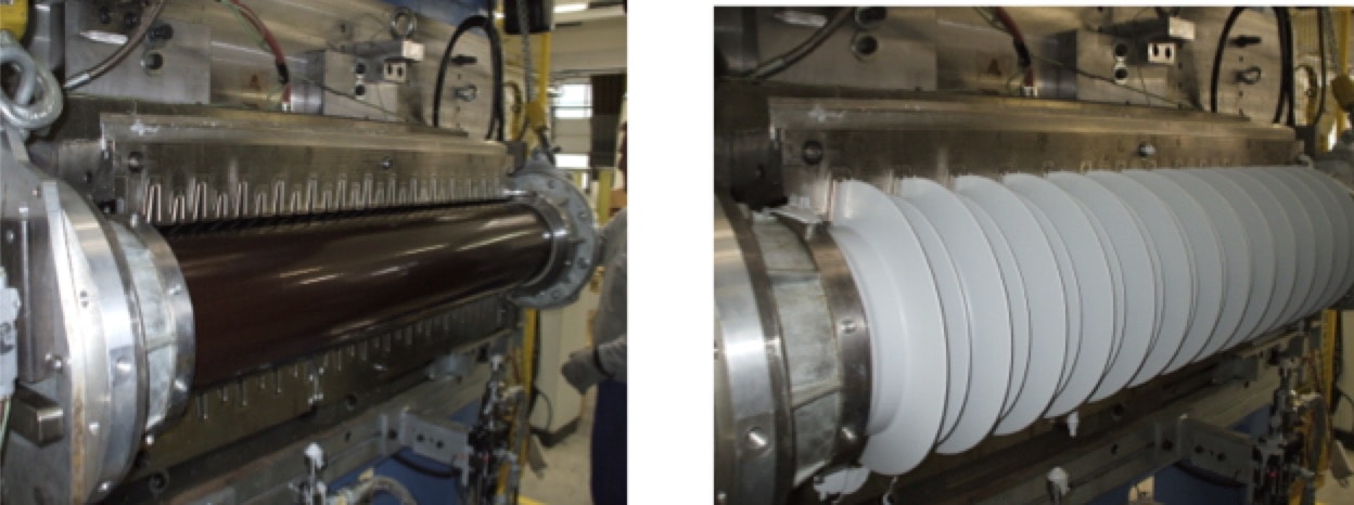
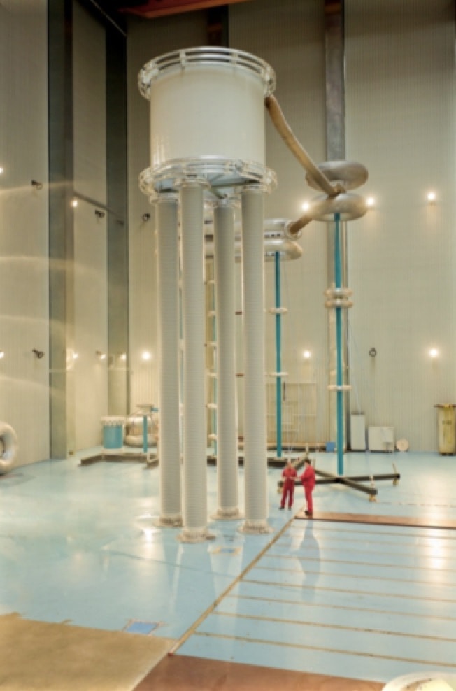
Dry turning pre-dried pugs is comparatively rare, with maximum solid core diameters of about 300 mm. While shed profile designs can be adapted in a highly flexible way, the production cycle for porcelain station post insulators is relatively long and costs are driven mainly by labor and energy. Fig. 2 illustrates progress in this technology by comparing number and size of modular units needed to satisfy the same application. Yet, while ceramic material makes for a good electrical insulator, it has limited mechanical performance. For example, strength of ceramic material is limited to 60 to 100 MPa design stress, a factor of 8-10 lower than for composite material (i.e. where design stress can range from 500 to 800 MPa).
Two different industrial production technologies are applied for composite station post and hybrid station post insulators:
• LSR/HTV Injection Molding
• HTV Extrusion Technology
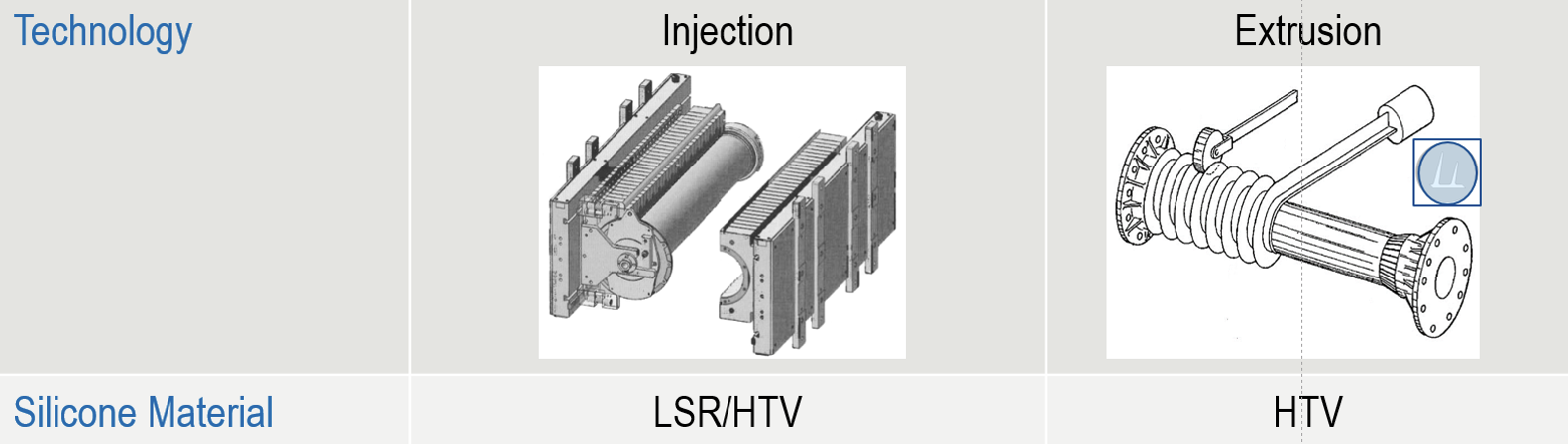
Injection molding technology is tool-based and preferred for large volume production of a single type of insulator. Shot lengths are typically up to 3000 mm. Design flexibility, however, is lower than with extrusion technology, which offers a wider spectrum of different possible shapes (e.g. conical) and shed profiles achieved with less tooling and set-up requirements.
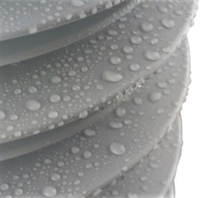
Modular production technology, which sees slip-on assembly of individual sheds, is also used for low volume, more specialized production. Surface hydrophobicity and the ability to transfer this property to the pollution layer (i.e. the hydrophobicity transfer mechanism or HTM) places silicone housings in a superior position to uncoated porcelain. Composite and hybrid station posts, like RTV silicone coated porcelain post insulators, have greater resistance to pollution flashover, especially under DC voltage stress.
Apart from HTM performance, tracking and erosion resistance is another important technical characteristic of silicone housings used in station post insulators. In this regard, HTV housing materials offer superior performance at AC and especially under DC voltage stress.

Application Spectra
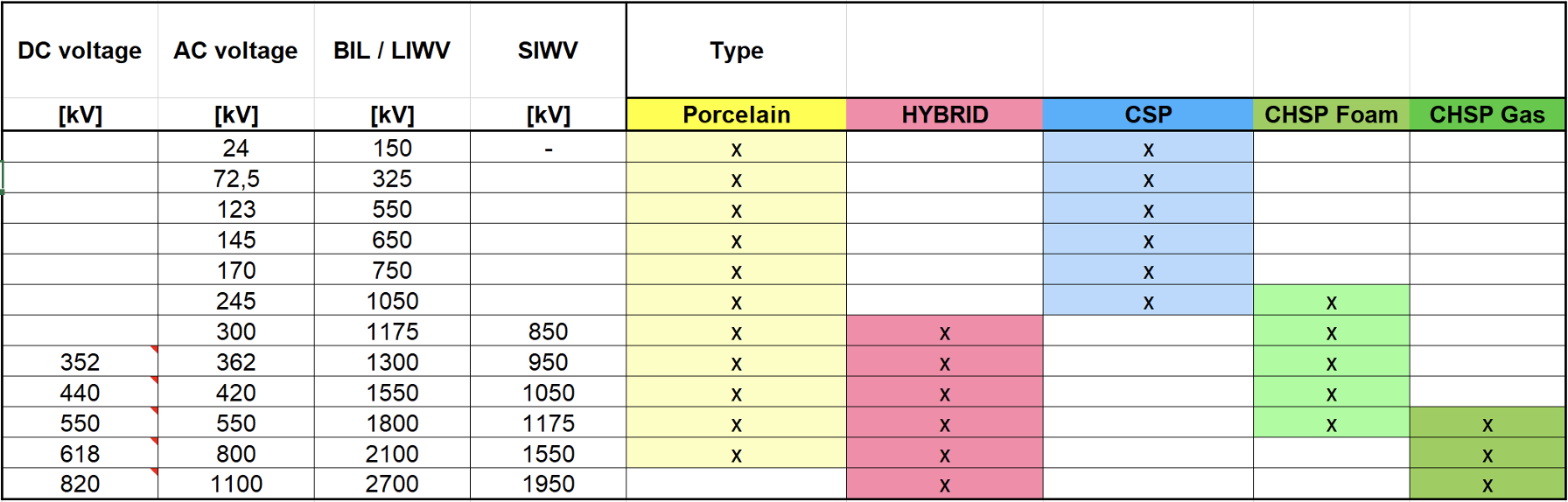
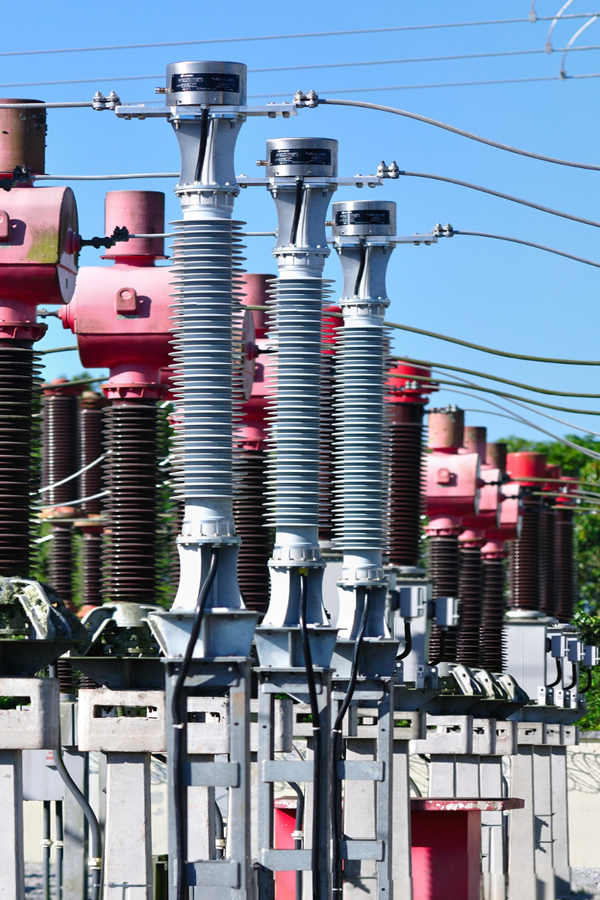
Table 1 shows the application spectra of different types of station post insulators. As evident, the widest range is covered by standard porcelain insulators, most without need for RTV coatings. In fact, their application is state-of-the-art at almost all voltage classes, including 800 kV. However, maximum feasible solid core diameter of 300 mm is a limiting factor when it comes to cantilever strength. In addition, the relatively high weight of solid core porcelain limits use in seismic applications. While RTV coatings enable high pollution resistance, they also significantly increase total production cost and also require special care to assure factory-coated station posts are not damaged during transport, handling or installation.
CSP type insulators offer important advantages in the voltage range up to 245 kV, including resistance to pollution, resilience, superior seismic performance and lower weight. For voltage classes above 245 kV, the CHSP type is preferred, especially since there are virtually no limitations in single unit length and diameter. For example, FRP tube diameters of more than 1000 mm are already in service. Solid media (e.g. foam-filled) CHSPs are applied in the medium voltage segment whereas applications at more than 550 kV typically see this type filled with insulating gas.
Applications:
• Bus bar supports (substations)
• Disconnector switches
• HVDC converters
• FACTS / platforms (UPFC, SVC, capacitive and reactive compensators)
• Coil supports
• Optical CT/VT supports
• Optical fiber bushings (station post type)
Advantages/Disadvantages:
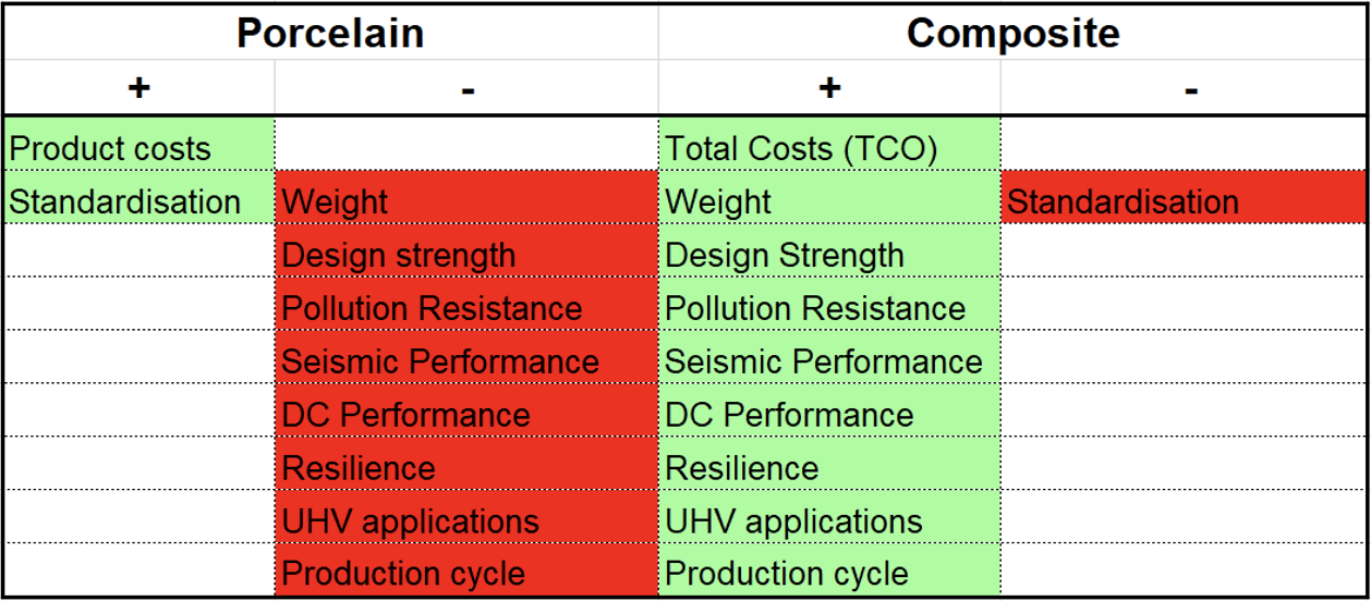
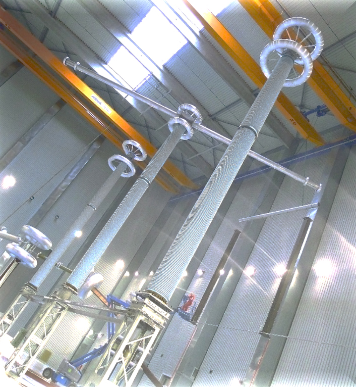
Fig. 9 shows CHSP coil support insulators, with length of 10 m and tube diameter of 580 mm, during a type test at a HV laboratory. Here, the coil is acting as a reactor at an HVDC converter station. The four CHSPs, in accordance with IEC 62772, are filled with gas whose pressure is controlled and monitored. The main load of these post insulators is compression and this type was selected for the application because of superior mechanical single-unit design along with excellent insulation performance of the hydrophobic silicone under pollution and DC voltage stress.
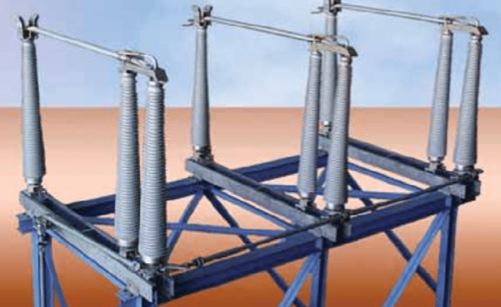
Application of a gas-filled CHSP in a UHV disconnector switch is shown in Fig. 10. An alternative solution might be a hybrid insulator, with low deflection under mechanical load.
One of the important drivers for application of CSPs and CHSPs is superior seismic resistance. In general, great effort is needed to qualify a multi-unit station post assembly made of porcelain insulators for seismic applications. Finite Element (FEM) calculations that consider the static and dynamic damping characteristics have to be performed in order to analyze theoretical performance. Then, the design process is run interactively considering weight, strength and damping of the entire assembly. Finally, most customers still require costly shaker table tests to simulate actual conditions. Such efforts and expense can be significantly reduced in the case of composite station posts since these are non-brittle, show high self-damping properties and can be designed with the combination of high strength and low weight.

Apart from seismic issues, CSPs and CHSPs also offer advantages when it comes to incorporation of the latest technologies. For example, Fig. 11 shows new apparatus that employs optical sensors to measure voltage and current (i.e. an optical CT/VT). The base technology in this application relies of optical-electronic equipment accommodated in the head or inside the hollow post insulator that acts as mechanical support carrying measuring device with connected conductor. Basically, it acts as an insulated bushing for the optical fiber that is led through the hollow core. Typically, the internal hollow volume is filled by an insulating foam or jelly or, in rare cases, with gas. Composite insulators dominate this emerging market due to the superior properties discussed above. Fig. 12 shows the innovative design of a 3-phase 362 kV disconnector for application in the seismic and high-pollution environment of Southern California. Only availability of CHSPs enables design of such innovative apparatus. Here, conically shaped insulators were chosen due to superior mechanical considerations, less weight and improved pollution performance. In such cases, total cost of ownership (TCO) that considers life cycle cost (LCC), maintenance issues, need for washing as well as resilience against terrorism, vandalism and seismic threats is increasingly the deciding factor in product selection.
Challenges & Future Developments
The next steps in continued development of station post technologies include more standardization for the portfolio of composite types,e.g. completion of standards for characteristics in IEC and ANSI. In ANSI, the TR types are missing while in IEC the range above 245 kV is not yet standardized in regard to characteristic types.Today, both porcelain and composite insulator technologies are mature. Still, there is potential when it comes to finding more economic and ecologically safe media to fill the internal volume of CHSPs. R&D is in progress towards this goal. Also, special insulating flanges are increasingly entering this market segment, especially for application in anti-magnetic couplings.
Hollow station post insulators are enabling design of new optical fiber bushings and optical CT/VT apparatus and, in general, there is a strong trend towards more use of composite insulators in these are other applications. Concerns in regard to expected service life have been basically resolved based on service experience that now exceeds 35 years.
One remaining challenge is to better define tests that ensure proven and stable designs and that help distinguish these from purely ‘cheap’ solutions that compromise long service life and quality and risk damaging user confidence in this technology. IEC and other industry Committees will play a key role in promoting development of proper test methods to prevent this. For example, the recently established Maintenance Team IEC TC 36 MT 24 (“Composite Insulators for Substation Products”) is dedicated to this task and to update related important standards as well as the base standard itself, i.e. IEC 61462.
Conclusions
The key advantages of composite station post insulators result from their reduced weight, high strength and superior pollution resistance as well as the improved design and manufacturing flexibility they allow. These benefits are particularly important for voltage classes exceeding 420 kV and for both 800 kV HVDC and 1200 kV UHV.
Over the next 20 years, composite station post insulators will likely outperform and replace conventional insulators in most if not all application areas due to economic, ecological and technical benefits. This process will likely only be accelerated if users base decisions according to the Total Cost of Ownership model, which considers not only initial acquisition cost but also supply chain and environmental requirements, maintenance needs and assumptions about risk and service life.
Listen to lectures on developments in design and application of station post insulators by experts such as Dr. Jens Seifert of Germany at the upcoming INMR WORLD CONGRESS in Bangkok, Thailand (Nov. 12-15, 2023).
 [inline_ad_block]